Patent application title: WASTE HEAT RECOVERY SYSTEM
Inventors:
IPC8 Class: AH02J346FI
USPC Class:
290 4 D
Class name: Prime-mover dynamo plants plural prime mover plural prime movers with fluid interconnection
Publication date: 2016-09-01
Patent application number: 20160254674
Abstract:
Connected in parallel to an expander and a condenser of a Rankine cycle
are n sets each including a different expander and a different condenser.
Devices are provided for stopping operations of the expanders in sets
connected in parallel, and a pressure sensor and a temperature sensor are
installed respectively in an inlet and outlet of an evaporator. An
electronic control unit sets or releases at least one of the operation
stopping devices such that a measured value of the temperature sensor
reaches a prescribed temperature value which is equal to or less than a
thermal decomposition temperature of a refrigerant and which is set in
advance, and the electronic control unit controls a rotational speed of a
refrigerant pump such that a measured value of the pressure sensor
reaches a prescribed pressure value set in advance.Claims:
1. A waste heat recovery system, comprising: a Rankine cycle in which a
refrigerant circulates in a refrigerant pump, an evaporator, an expander,
and a condenser in sequence; a controller for controlling the Rankine
cycle, wherein the waste heat recovery system uses waste heat from an
internal combustion engine as a heating source for the evaporator; a set
including the expander and the condenser and at least one different set
including a different expander and a different condenser are connected in
parallel with each other; a device for stopping an operation of the
expander in the different set connected in parallel; a pressure sensor in
an inlet of the evaporator and a temperature sensor in an outlet of the
evaporator, wherein the controller sets or releases at least one of the
operation stopping devices such that a measured value of the temperature
sensor reaches a prescribed temperature value which is set in advance and
is equal to or less than a thermal decomposition temperature of the
refrigerant, and wherein the controller controls a rotational speed of
the refrigerant pump such that a measured value of the pressure sensor
reaches a prescribed pressure value which is set in advance.
2. The waste heat recovery system according to claim 1, wherein said operation stopping device is a brake which applies a load to a rotating shaft of said different expander.
Description:
TECHNICAL FIELD
[0001] The present invention relates to a waste heat recovery system, or more specifically, to a waste heat recovery system which recovers waste heat from an internal combustion engine at high efficiency without causing thermal decomposition of a refrigerant in a Rankine cycle.
BACKGROUND ART
[0002] As described in Japanese patent application Kokai publication No. Hei 11-51582 (Patent Document 1), use of a Rankine cycle has heretofore been proposed for the purpose of making improvement for fuel consumption by recovering waste heat from an internal combustion engine. In order to efficiently operate the Rankine cycle, it is necessary to adjust an evaporation temperature of a refrigerant by changing a pressure thereof. A fluorocarbon-based refrigerant used in a waste heat recovery Rankine cycle gasifies at a low temperature, and therefore has a feature that the refrigerant set at an appropriate pressure allows a Rankine cycle to operate with a heat source at a low temperature equal to or less than 100.degree. C. On the other hand, this technique has a drawback that it is not possible to make the temperature of the refrigerant higher than its thermal decomposition temperature.
[0003] During recovery of waste heat of exhaust gas from an internal combustion engine of an automobile or the like, the temperature of the exhaust gas varies significantly in a range from 100.degree. C. to 800.degree. C. depending on a driving condition. Further, when the temperature of the exhaust gas is high, an exhaust gas flow rate also increases in proportion thereto. As a consequence, an amount of waste heat also becomes very large. In the meantime, regarding waste heat from cooling water in the internal combustion engine, the temperature of the cooling water varies less significantly in a range from 80.degree. C. to 100.degree. C., whereas an amount of the waste heat varies significantly.
[0004] In the case of recovering the waste heat whose amount of heat varies significantly as described above, a flow rate of the refrigerant should be changed appropriately in order to maintain the temperature of the refrigerant in the Rankine cycle at the evaporation temperature, which is equal to or less than the thermal decomposition temperature and is under a pressure that enables efficient operation.
[0005] However, in the conventional structure of the waste heat recovery Rankine cycle provided with one expander and one pump only, it has been difficult to change the flow rate of the refrigerant in such a way as to maintain a constant temperature while keeping the pressure at a prescribed value.
PRIOR ART DOCUMENT
Patent Document
[0006] Patent Document 1: Japanese patent application Kokai publication No. Hei 11-51582
SUMMARY OF THE INVENTION
Problem to be Solved by the Invention
[0007] An object of the present invention is to provide a waste heat recovery system, which is capable of recovering waste heat from an internal combustion engine at high efficiency without causing thermal decomposition of a refrigerant in a Rankine cycle.
Means for Solving the Problem
[0008] A waste heat recovery system according to the present invention which achieves the above object includes: a Rankine cycle in which a refrigerant circulates in a refrigerant pump, an evaporator, an expander, and a condenser in sequence; and controlling means for controlling the Rankine cycle, in which the waste heat recovery system is designed to use waste heat from an internal combustion engine as a heating source for the evaporator. The waste heat recovery system is characterized in that: a set including the expander and the condenser and at least one different set including a different expander and a different condenser are connected in parallel with each other; operation stopping means is provided for stopping an operation of the expander in the different set connected in parallel; a pressure sensor is installed in an inlet of the evaporator and a temperature sensor is installed in an outlet of the evaporator; the controlling means sets or releases at least one of the operation stopping means such that a measured value of the temperature sensor reaches a prescribed temperature value which is set in advance and is equal to or less than a thermal decomposition temperature of the refrigerant; and the controlling means controls a rotational speed of the refrigerant pump such that a measured value of the pressure sensor reaches a prescribed pressure value which is set in advance.
Effects of the Invention
[0009] According to the waste heat recovery system of the present invention, multiple expanders and condensers as in the conventional Rankine cycle are connected in parallel so that flow passage or passages can be appropriately selected depending on the temperature of the refrigerant, and the temperature of the refrigerant in the Rankine cycle can always be maintained at a temperature value equal to or less than the thermal decomposition temperature and under the pressure at which the refrigerant is operated at high efficiency even when an amount of waste heat from the internal combustion engine varies. Thus, it is possible to recover the waste heat from the internal combustion engine at high efficiency without causing thermal decomposition of the refrigerant in the Rankine cycle.
BRIEF DESCRIPTION OF THE DRAWINGS
[0010] FIG. 1 is a configuration diagram of a waste heat recovery system according to an embodiment of the present invention.
[0011] FIG. 2 is a flowchart describing contents of control by an ECU in the waste heat recovery system according to the embodiment of the present invention.
MODES FOR CARRYING OUT THE INVENTION
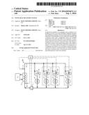
[0012] An embodiment of the present invention will be described below with reference to the drawings. FIG. 1 shows a waste heat recovery system according to the embodiment of the present invention. Note that arrows in FIG. 1 show flowing directions of a fluid.
[0013] This waste heat recovery system is mounted on a vehicle such as a truck, provided with a Rankine cycle 6 in which a refrigerant 5 circulates in a refrigerant pump 1, an evaporator 2, an expander 3, and a condenser 4 in sequence, and is designed to recover waste heat from a diesel engine 7 which is an internal combustion engine.
[0014] Exhaust gas from the diesel engine 7, cooling water for an engine body, and the like are used as a heating source for the evaporator 2 in the Rankine cycle 6. On the other hand, cooling water for an intercooler, and the like are used as a cooling source for the condenser 4. Meanwhile, examples of the refrigerant 5 include water, ethanol, a fluorine compound, and the like.
[0015] The refrigerant 5 flowing through the Rankine cycle 6 is compressed in a liquid state by the refrigerant pump 1, and is then isobarically heated into a high-pressure gas by the evaporator 2. Thereafter, the refrigerant 5 rotatably drives an electric generator 9 through a turbine shaft 8 while being adiabatically expanded by the expander 3, and then returns into the liquid while being isobarically cooled by the condenser 4.
[0016] Moreover, connected in parallel to the expander 3 and the condenser 4 of the Rankine cycle 6 are n (n is a natural integer) sets S each of which includes a different expander E and a different condenser C having the same specifications as those of the expander 3 and the condenser 4. Meanwhile, provided to the expanders E.sub.1 to E.sub.n in the sets S.sub.1 to S.sub.n, respectively, are operation stopping means B.sub.1 to B.sub.n to be set or released so as to stop or activate operations of the expanders E.sub.1 to E.sub.n. Although the operation stopping means B are not limited to particular means, examples of the means include brakes which apply mechanical loads to turbine shafts A of the expanders E. When the operation stopping means B.sub.n is set, the refrigerant 5 is kept from circulation in the corresponding set S.sub.n.
[0017] Furthermore, a pressure sensor 10 configured to measure a pressure of the refrigerant 5 is installed on an inlet side of the evaporator 2 and a temperature sensor 11 configured to measure a temperature of the refrigerant 5 is installed on an outlet side thereof, respectively.
[0018] Each of the operation stopping means B.sub.1 to B.sub.n, the refrigerant pump 1, the pressure sensor 10, and the temperature sensor 11 described above is connected to an ECU 12, which is controlling means, through a signal line (indicated with a chain dashed line).
[0019] Here, the number n of the sets S described above is appropriately determined based on specifications and operating conditions of the diesel engine 7, and performances of the refrigerant pump 1 and the evaporator 2.
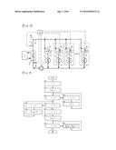
[0020] Contents of control by the ECU 12 in the above-described waste heat recovery system will be described below based on FIG. 2.
[0021] The ECU initializes a control variable i (an integer) (S10). Then, the ECU inputs a measured value T of the temperature sensor 11 (S15), and either sets or releases at least one of the operation stopping means B.sub.1 to B.sub.n such that the measured value T reaches a prescribed temperature value Ts which is set in advance and is equal to or less than a thermal decomposition temperature of the refrigerant 5. The prescribed temperature value Ts is a temperature at which the refrigerant 5 is operated at high efficiency in the Rankine cycle 6, and which is determined based on the type of the refrigerant 5.
[0022] Specifically, when the measured value T is below the prescribed temperature value Ts (S20), an amount of waste heat from the diesel engine 7 is determined to be relatively small. Hence, the operation stopping means B.sub.1 to B.sub.n are set in sequence (S25 and S30) so as to cause the refrigerant 5 to flow either only through the conventional expander 3 as well as the conventional condenser 4, or only through an appropriate number of the sets S in addition thereto. On the other hand, when the measured value T is above the prescribed temperature value Ts (S35), the amount of waste heat from the diesel engine 7 is determined to be relatively large. Hence, the operation stopping means B.sub.1 to B.sub.n are released in sequence (S40 and S45) so as to cause the refrigerant 5 to flow through an appropriate number of the sets S in addition to the conventional expander 3 and the conventional condenser 4.
[0023] Then, when the measured value T is determined to be equal to the prescribed temperature value Ts (S50), a measured value P of the pressure sensor 10 is inputted (S55), and a rotational speed of the refrigerant pump 1 is controlled (S60 and S65) such that the measured value P reaches a prescribed pressure value Ps which is set in advance. The prescribed pressure value Ps is a pressure at which the refrigerant 5 is operated at high efficiency in the Rankine cycle 6, and which is determined based on the type of the refrigerant 5.
[0024] The steps 10 to 65 described above are repeated while the diesel engine 7 is in operation.
[0025] By performing the control as described above, the temperature of the refrigerant 5 in the Rankine cycle 6 is always maintained at the temperature value equal to or less than the thermal decomposition temperature and under the pressure at which the refrigerant 5 is operated at high efficiency even when the amount of waste heat from the diesel engine 7 varies. Thus, it is possible to recover the waste heat from the diesel engine 7 at high efficiency without causing thermal decomposition of the refrigerant 5.
[0026] The waste heat recovery system of the present invention can be mounted not only on a vehicle such as the above-mentioned truck, but also on a fixed power generator, a large-size electric generator, and the like. Meanwhile, the internal combustion engine is not limited only to the diesel engine 7.
EXPLANATION OF REFERENCE NUMERALS
[0027] 1 refrigerant pump
[0028] 2 evaporator
[0029] 3, E expander
[0030] 4, C condenser
[0031] 5 refrigerant
[0032] 6 Rankine cycle
[0033] 7 diesel engine
[0034] 10 pressure sensor
[0035] 11 temperature sensor
[0036] 12 ECU
[0037] B operation stopping means
[0038] S set
User Contributions:
Comment about this patent or add new information about this topic:
Images included with this patent application:
 |  |
| Similar patent applications: | |
| Date | Title |
|---|---|
| 2016-06-16 | Short-term operation optimization method of electric power system including large-scale wind power |
| 2016-12-29 | Thermal energy recovery system |
| 2013-01-10 | Waste heat recovery |
| 2016-07-07 | Hvac system with energy recovery mechanism |
| 2016-12-29 | Apparatus for receiving, storing, carrying and discharging a liquid as well as an overall system and vehicle |
| New patent applications in this class: | |
| Date | Title |
|---|---|
| 2013-01-10 | Storage of compressed air in wind turbine support structure |
| 2012-09-27 | Eccentric dual rotor assembly for wind power generation |
| 2010-01-21 | Aircraft combination engines plural airflow conveyances system |
| 2009-05-14 | Combined cycle power plant |
| Top Inventors for class "Prime-mover dynamo plants" | |
| Rank | Inventor's name |
|---|---|
| 1 | Henrik Stiesdal |
| 2 | Per Egedal |
| 3 | Akira Yasugi |
| 4 | Takatoshi Matsushita |
| 5 | Lowell L. Wood, Jr. |