Patent application title: Negative Pressure Updraught Pouring Method
Inventors:
IPC8 Class: AB22D1806FI
USPC Class:
1 1
Class name:
Publication date: 2016-08-25
Patent application number: 20160243614
Abstract:
A negative pressure updraught pouring method is provided, wherein a
melting furnace is filled with molten steel and a flat plate with a
suction pipe is covered on a top end of the melting furnace with the
bottom end of the suction pipe is dipped into the molten steel; a
ventilated mold is placed on the flat plate such that a flow path system
of the mold is connected with a top end of the suction pipe; and a
chamber is covered on the mold and the flat plate, and the air inside the
chamber is drawn out to reduce the air pressure inside the chamber and a
cavity of the mold, thereby the molten steel inside the melting furnace
is sucked into the mold cavity through the suction pipe and the flow path
system by the negative pressure formed inside the chamber for forming a
cast.Claims:
1. A negative pressure updraught pouring method provided for at least one
mold to form at least one cast, in which a mold cavity and a flow path
system connected with each other are disposed inside the mold, the method
comprising following steps of: a. covering a top end of a melting furnace
with a flat plate having a suction plate, filling the melting furnace
with molten steel, and dipping a bottom end of the suction pipe into the
molten steel; b. placing the mold on the flat plate in order to connect
the flow path system of the mold with a top end of the suction pipe,
wherein the mold has an air passage connected with the mold cavity, the
mold is a sand mold, and the air passage on the mold is a gap between
each of sand grains of the sand mold; c. placing a chamber over the mold
and the flat plate, drawing the air inside the chamber out to reduce the
air pressure inside the chamber and the mold cavity, sucking the molten
steel inside the melting furnace upwardly through the suction pipe in
order to flow the molten steel into the mold cavity; and d. solidifying
the molten steel within a gate between the flow path system and the mold
cavity, before the molten steel inside the mold cavity is completely
solidified relieving the negative air pressure inside the chamber in
order to flow the molten steel inside the flow path system back into the
melting furnace, and after the molten steel completely flows back into
the melting furnace removing the chamber and detaching the mold from the
flat plate in order that the molten steel inside the mold continues to
cool down.
2. (canceled)
3. (canceled)
4. The negative pressure updraught pouring method as claimed in claim 1, wherein the temperature of the molten steel inside the melting furnace is between 1400.degree. C. and 1550.degree. C.
Description:
BACKGROUND OF THE INVENTION
[0001] 1. Field of Invention
[0002] The present invention relates to a pouring method and more particularly to a negative pressure updraught pouring method used for draughting molten steel upwards into a mold to form a cast by negative pressure.
[0003] 2. Description Of The Related Art
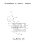
[0004] Referring to FIG. 5, the Gravity pouring method employed by conventional iron and steel foundry plants mainly comprises steps of: after steel is fused to 1450.about.1700.degree. C. by a melting furnace, the high temperature molten steel is filled in an iron bucket (d) and then the molten steel is poured and casted into a pre-manufactured mold (a); the molten steel is poured into a mold cavity c through a pouring basin (b1), a vertical sprue (b2), a runner (b3) and a gate (b4) of a flow path system (b) by gravitational effect; and the cooled and solidified molten steel is taken out from the mold (a). The solidified molten steel is cleaned and processed properly for obtaining a cast required.
[0005] The above pouring method is mainly used in iron and steel foundry. Nevertheless, the pouring method has the following drawbacks based on the foundry costs and quality of casts:
[0006] 1. For casts with a thickness below 3.5 mm, the molten steel is required for passing through the flow path system when it is casted into the sand mold by gravitational effect. Flowing speed of the molten steel is not too fast due to the obstruction of the air in the mold cavity. The thinner is the thickness of the cast; the slower is the flowing speed. The longer is the flowing path; the faster is the quenching speed of the molten steel. Therefore, the thin thickness of the cast is hard to form if the temperature of the molten steel is not high and the flowability is poor. As a result, it is difficult to obtain casts with good quality.
[0007] 2. When the melting temperature reaches 1700.degree. C. or higher, even though the flowability of the molten steel can be increased for forming casts with a thin thickness, but not only that the electricity consumption is increased, the lifespan of refractory materials of the melting furnace is shortened substantially after the melting temperature is increased. The frequency for changing the refractory materials has to increase which will increase the costs for changing the refractory materials and reduce the production capacity due to the downtime for changing. Furthermore, when the melting temperature of the molten steel is over 1700.degree. C., the refractory materials of the melting furnace will be fused with the molten steel. As a result, the amount of oxide-containing impurities in the molten steel increases which will affect the purity and mechanical property of the steel casts.
[0008] During the pouring process, the molten steel is required to fill up the flow path system including the pouring basin, the vertical sprue and the runner for flowing into the mold cavity. The molten steel inside the flow path system and that inside the mold cavity will be cooled down and solidified at the same time. The molten steel retaining inside the flow path system will increase the consumption of molten steel. As a result, the ratio (i.e. yield) of the amount of casts and that of the total pouring molten steel cannot be enhanced effectively. The ineffectiveness of enhancing the yield means the amount of molten steel cannot be saved effectively, the energy source cannot be saved effectively and thus the production costs cannot be reduced effectively.
SUMMARY OF THE INVENTION
[0009] In view of the above, a negative pressure updraught pouring method of the present invention is provided for improving the afore-mentioned drawbacks of the conventional structures and achieving the following objectives.
[0010] A primary objective of the present invention is to provide a negative pressure updraught pouring method for solving the problem of difficulty in forming casts with a thin thickness when the molten steel temperature is not high and meeting the requirements of casts with a thin thickness.
[0011] Another objective of the present invention is to provide a negative pressure updraught pouring method for solving the drawback of the high molten steel temperature in order that the power consumption can be reduced, the loss and changing frequency of refractory materials can be reduced, the purity and mechanical property of casts can be enhanced and thus the production costs can be reduced.
[0012] Another objective of the present invention is to provide a negative pressure updraught pouring method for solving the drawback of redundant molten steel remaining inside the flow path system which causes the ineffectiveness of enhancing the yield ratio in order that the costs for reclaiming the molten steel can be saved and the output can be increased effectively.
[0013] Another objective of the present invention is to provide a negative pressure updraught pouring method for solving the drawback of the requirement of using the iron bucket for pouring. The iron bucket and related equipment are no longer needed and thus the production costs can be reduced.
[0014] In order to achieve the above-mentioned objectives, the negative pressure updraught pouring method of the present invention is provided for forming at least one cast by using at least one mold. A mold cavity and a flow path system connected with each other are disposed inside the mold. The negative pressure updraught pouring method comprises following steps of: a) a flat plate with a suction pipe is covered on a top end of a melting furnace, the melting furnace is filled with fused molten steel, and a bottom end of the suction pipe is dipped into the molten steel; b) an air passage connected with the mold cavity is formed on the mold, and the mold is placed on the flat plate in order that the flow path system of the mold is connected with a top end of the suction pipe; c) a chamber is covered on the mold and the flat plate, and the air inside the chamber is drawn out to reduce the air pressure inside the chamber and the mold cavity, the molten steel inside the melting furnace is sucked upwardly and flowed into the mold cavity through the suction pipe; and d) solidifying the molten steel within a gate between the flow path system and the mold cavity, and then the negative air pressure inside the chamber is relieved so that the molten steel inside the flow path system can be flowed back into the melting furnace.
[0015] When the present invention is embodied, the negative pressure updraught pouring method further comprises a step of: after the step d, the chamber is removed and the mold is detached from the flat plate.
[0016] When the negative pressure updraught pouring method is embodied, the mold is a sand mold, the air passage on the mold is a gap between each one of sand grains of the sand mold, and the temperature of the fused molten steel inside the melting furnace is between 1400.about.1550.degree. C.
[0017] The present invention will become more fully understood by reference to the following detailed description thereof when read in conjunction with the attached drawings.
BRIEF DESCRIPTION OF THE DRAWINGS
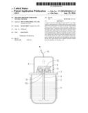
[0018] FIG. 1 is an explosive view of elements used with a preferred embodiment of a negative pressure updraught pouring method of the disclosure;
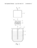
[0019] FIG. 2 is a sectional assembly view of the elements used with the preferred embodiment of the negative pressure updraught pouring method of the disclosure;
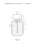
[0020] FIG. 3 is a sectional view of the preferred embodiment of the negative pressure updraught pouring method of the disclosure when a negative pressure is formed;
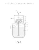
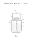
[0021] FIG. 4 is a sectional view of molten steel of the preferred embodiment of the negative pressure updraught pouring method of the disclosure being flowed back into a melting furnace; and
[0022] FIG. 5 is a sectional view of molten steel being casted into a mold used with a conventional sand mold pouring method.
DETAILED DESCRIPTION OF THE PREFERRED EMBODIMENTS
[0023] Please refer to FIGS. 1 to 4. A preferred embodiment of a negative pressure updraught pouring method of the present invention comprises following steps of:
[0024] a) a flat plate 3 with a suction pipe 4 is covered on a top end of a melting furnace 2, the melting furnace 2 is filled with fused molten steel 9, and a bottom end of the suction pipe 4 is dipped into the molten steel 9;
[0025] b) an air passage 52 connected with a mold cavity 51 is formed on a mold 5, and the mold 5 is placed on the flat plate 3 in order that a flow path system 53 of the mold 5 is connected with a top end of the suction pipe 4;
[0026] c) a chamber 6 is covered on the mold 5 and the flat plate 3, and the air inside the chamber 6 is drawn out to reduce the air pressure inside the chamber 6 and the mold cavity 51, the molten steel 9 inside the melting furnace 2 is sucked upwardly and flowed into the mold cavity 51 through the suction pipe 4 for forming a cast; and
[0027] d) solidifying the molten steel within a gate 54 between the flow path system 53 and the mold cavity 51, and then the negative air pressure inside the chamber 6 is relieved so that the molten steel 9 inside the flow path system 53 can be flowed back into the melting furnace 2.
[0028] The melting furnace 2 in the step is a coil heating type melting furnace. The melting temperature of the molten steel 9 is controlled between 1400.about.1550.degree. C. The suction pipe 4 is penetrated through the flat plate 3 vertically and an opening of the bottom end of the suction pipe 4 is dipped into the molten steel 9. An opening of the top end of the suction pipe 4 and a top surface of the flat plate 3 are roughly on a same plane.
[0029] The mold 5 in the step b is a sand mold. The air passage 52 on the mold 5 is a gap between each one of sand grains of the sand mold for creating air permeable effect. An intake 531 of the flow path system 53 of the mold 5 is formed on a bottom surface of the mold 5 in order that the intake 531 can be aligned with the opening of the top end of the suction pipe 4 when the mold 5 is placed on the flat plate 3, and thus the flow path system 53 of the mold 5 can be connected with the top end of the suction pipe 4.
[0030] In the step c, the chamber 6 is a hollow container with a bottom opening. A top end of the chamber 6 is connected with an air exhaust tube 61 in order that a vacuum pump is used for extracting air inside the chamber 6 when the chamber 6 is covered on the mold 5 and the flat plate 3. Due to the air permeability of the mold 5, the air pressure inside the chamber 6 is the same as that of the mold cavity 51, the flow path system 53 and the suction pipe 4. Therefore, negative pressure can be used for sucking the molten steel 9 inside the melting furnace 2. The molten steel 9 can flow upward through the suction pipe 4 and then into the mold cavity 51 through the flow path system 53. When the negative pressure updraught pouring method of the present invention is embodied, a plurality of the mold cavity 51 can be disposed for forming a plurality of casts at the same time.
[0031] In the step d, after the molten steel 9 has flowed into the mold cavity 51, the molten steel 9 is allowed to stand for a period of time. Then, before the molten steel 9 inside the mold cavity 51 is completely solidified, and the molten steel 9 within the gate 54 between the flow path system 53 and the mold cavity 51 is solidified, the negative air pressure inside the chamber 6 is relieved so that the unsolidified molten steel 9 inside the flow path system 53 can flow back downwardly into the melting furnace 2.
[0032] After the molten steel 9 has completely flowed back into the melting furnace 2, remove the chamber 6 and detach the mold 5 from the flat plate 3 in order that the molten steel 9 inside the mold 5 continues to cool down. A new mold 5 can be placed on the flat plate 3 for performing pouring again.
[0033] As a conclusion, the negative pressure updraught pouring method of the present invention has the following advantages:
[0034] 1. The present invention employs negative pressure updraught method to suck the molten steel into the mold cavity. The thickness of the cast can be reduced to below 2.5 mm. Thus, products that demand special requirement of casts with a thin thickness can be met.
[0035] 2. The present invention employs negative pressure updraught method to suck the molten steel into the mold cavity. Even though the molten steel temperature is between 1400.about.1550.degree. C., the molten steel can still flow smoothly inside the flow path system. Therefore, the decrease of the melting temperature of the molten steel not only can reduce the power consumption in order to save energy source, the loss of refractory materials fused into the molten steel can be reduced in order that the purity and mechanical property of the cast can be enhanced. As a result, the changing frequency of the refractory materials of the melting furnace can be reduced in order to reduce the production costs.
[0036] 3. The present invention allows the unsolidified molten steel to flow back into the melting furnace for being used in the next pouring after the present pouring is finished. Therefore, the yield ratio can be enhanced effectively, the costs for reclaiming can be saved and the output can be increased.
[0037] 4. The present invention employs negative pressure updraught method to suck the molten steel into the mold cavity. Therefore, the melting temperature of the molten steel can be reduced. Furthermore, shorter flow path system can be used. No impurities will be mixed in the molten steel when the unsolidified molten steel flows back into the melting furnace. Consequently, negative effects on the mechanical property of the steel casts caused by impurities can be prevented.
[0038] 5. The melting furnace of the present invention is a coil heating type melting furnace. Fused molten steel can be provided directly for the sucking of the suction pipe in order that casts can be formed. Therefore, not only that the pouring process is made more simplified and more effective, no iron bucket and related equipment are needed for reducing the production costs.
[0039] As a conclusion from the above disclosed descriptions, the expected objectives can be achieved by the negative pressure updraught pouring method of the present invention which not only can allow casts to have a thin thickness, the production costs can be reduced, output can be enhanced, manufacturing process can be simplified, and quality of casts can be ensured.
[0040] Although the embodiments of the present invention have been described in detail, many modifications and variations may be made by those skilled in the art from the teachings disclosed hereinabove. Therefore, it should be understood that any modification and variation equivalent to the spirit of the present invention be regarded to fall into the scope defined by the appended claims.
User Contributions:
Comment about this patent or add new information about this topic:
Images included with this patent application:
 |  |
 |  |
 |  |
| New patent applications in this class: | |
| Date | Title |
|---|---|
| 2022-09-22 | Electronic device |
| 2022-09-22 | Front-facing proximity detection using capacitive sensor |
| 2022-09-22 | Touch-control panel and touch-control display apparatus |
| 2022-09-22 | Sensing circuit with signal compensation |
| 2022-09-22 | Reduced-size interfaces for managing alerts |