Patent application title: Universal Service Enclosure
Inventors:
IPC8 Class: AE04F1900FI
USPC Class:
1 1
Class name:
Publication date: 2016-08-11
Patent application number: 20160230402
Abstract:
A universal services enclosure system, with a centralizing universal back
panel, and universal enclosure, which attaches to a house or building, is
designed to centralize, enclose, and visually hide, all current and
future exterior service boxes, utility connections, and junction points
to that building, in a manner that matches and/or complements the
existing exterior facade and finish of that house or building.Claims:
1. A Universal Service Enclosure System, with a Universal Back Panel, and
Universal Enclosures, that centralize the placement of multiple exterior
utility and service access or entry points to a home or building, within
the same enclosure, with a design and fashion that matches or compliments
the look of the exterior facade and finish of the home or building, is
modular, interchangeable, can accommodate the look of more than one
facade or finish with a single enclosure, is durable, paintable, weather
resistant, easily attached and easily removable, and is designed to
accommodate current and future service entry points of a home or
building, along with their independent junction boxes, cables, pipes,
conduits, and wires.
2. The modular and interchangeable nature of claim 1 wherein the enclosure system incorporates multiple connecting modules i.e. top cap, body, center band, and base, along with a variety of finishes or textures, within the same interlocking enclosure unit or system.
3. The conceptualization of a centralized enclosure system design, that can be placed on a home or building at the time of construction, or after completion of construction, that covers multiple service entry points to a house or building and allows for both current and future service connections to be enclosed in the same unit.
Description:
CROSS-REFERENCE TO RELATED APPLICATIONS
[0001] Not Applicable
STATEMENT REGARDING FEDERALLY SPONSORED RESEARCH OR DEVELOPMENT
[0002] Not Applicable
REFERENCE TO SEQUENCE LISTING, A TABLE, OR A COMPUTER PROGRAM LISTING COMPACT DISK APPENDIX
[0003] Not Applicable
TECHNICAL FIELD
[0004] The present invention is associated with the residential and light commercial construction industry. It generally relates to a universal enclosure for all utilities and services that enter a structure or building. More specifically, it provides a central point of entry and enclosure for placement of, and access to, all service connections to a home or building, and is designed in manner to match, enhance, and complement the existing facade and finish of the home or building to which it is attached.
BACKGROUND OF THE INVENTION
[0005] The standing convention for the placement of utility and service entry points to a home or building are only partially regulated by utility companies, city, and county building codes. As a result, service conduit, pipes, meters, and junction boxes are inconsistently placed around a home's exterior. The placement of these service points are often at the discretion of the various service company installers (i.e. cable, phone, internet, satellite, security, solar, and other auxiliary service providers). This leaves an unsightly collection of mismatched and odd sized pipes, panels and junction boxes, which is unsightly and often hazardous.
[0006] There have been other patents that have attempted to ornamentally cover gas meters such as Breaux's Utility Box Trim Decor Kit (US Patent No. 202/0250700 A1) or electric meters such as Cabello-Colon's Cover for Electric Meter (U.S. Pat. No. 6,583,359B1), George's Utility Meter Cover (Des. 358560), or Seeley's Utility Meter Cover (Des. 346,976). None however have addressed the need to centralize all of the service boxes and entry points in a single organized universal service enclosure and system, which is easily located, easily accessible, can accommodate future service connections, and matches or complements the overall appearance of the service entry area to the home or building which it is attached to. With the advances of technology, along with the expansion of internet and digital media access via cable, satellite, and fiber optics, and the growth of residential and small business solar and wind power generation, it is expected that even more service entry points will be added to existing residential and commercial structures in the future. Currently there is no centralized access point and enclosure such as a universal service enclosure, that maintains and compliments the existing exterior facade and finish of a home or business structure.
SUMMARY OF THE INVENTION
[0007] The present invention is a universal service enclosure, and system, designed to match or complement the existing exterior facade and finish of a house, apartment building, or business structure, in a manner that provides a visually appealing and centralized entry point to that house, building, or structure, for placement of, and access to, all exterior service connections to that building, including but not limited to current and future, satellite, phone, data and multimedia cables and their service boxes, utility meters and their associated pipes and cables, circuit breaker boxes, home security system service boxes, solar, wind power, and future services entry points.
BRIEF DESCRIPTION OF THE DRAWINGS
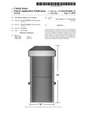
[0008] FIG. 1 represents the "Generic" or "Basic" version of the present invention from five perspectives or views, with standard dimensions.
[0009] FIG. 1-a is the back or anterior perspective of the generic version.
[0010] FIG. 1-b is the front perspective of the generic version.
[0011] FIG. 1-c is a side view of the generic version.
[0012] FIG. 1-d is a cabinet perspective of the generic version.
[0013] FIG. 1-e is a top down perspective of the generic version.
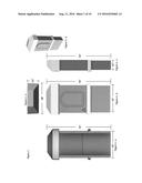
[0014] FIG. 2 represents the "Generic" or "Basic" version of the present invention from seven different perspectives or views.
[0015] FIG. 2-a is a view of the invention from a front, left side, and top perspective;
[0016] FIG. 2-b is a front only perspective of the invention;
[0017] FIG. 2-c is view from the back showing the open nature of the enclosure;
[0018] FIG. 2-d is a view from looking down from the top of the invention;
[0019] FIG. 2-e is a view of the invention from a front, right side, and top perspective;
[0020] FIG. 2-f is a view of the invention from a front, left side, and top perspective;
[0021] FIG. 2-g is a view looking up of the invention from the bottom
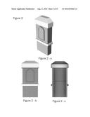
[0022] FIG. 3 represents the "Classic" or "Lapboard/Siding" version of the present invention from seven perspectives.
[0023] FIG. 3-a is a view of the invention from a front, left side, and top perspective;
[0024] FIG. 3-b is a front only perspective of the invention;
[0025] FIG. 3-c is view from the back showing the open nature of the enclosure;
[0026] FIG. 3-d is a view from looking down from the top of the invention;
[0027] FIG. 3-e is a view of the invention from a front, right side, and top perspective;
[0028] FIG. 3-f is a view of the invention from a front, left side, and top perspective;
[0029] FIG. 3-g is a view looking up of the invention from the bottom.
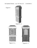
[0030] FIG. 4 represents the "Brick" version of the present invention from three perspectives.
[0031] FIG. 4-a is a view of the invention from a front, left side, and top perspective;
[0032] FIG. 4-b is a front only perspective of the invention;
[0033] FIG. 4-c is view from the back showing the open nature of the enclosure;
[0034] FIG. 5 represents the "Stone" version of the present invention from three perspectives.
[0035] FIG. 5-a is a view of the invention from a front, left side, and top perspective;
[0036] FIG. 5-b is a front only perspective of the invention;
[0037] FIG. 5-c is view from the back showing the open nature of the enclosure;
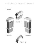
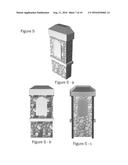
[0038] FIG. 6 depicts the individual components that make up the "Customizable" version of the current invention.
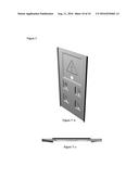
[0039] FIG. 7 depicts the centralizing Universal Back Panel of the current invention from three perspectives.
[0040] FIG. 7-a is a front view of the universal back panel;
[0041] FIG. 7-b is a view of the universal back panel from a front, left side, and top perspective;
[0042] FIG. 7-c is a view of the universal back panel from the top down perspective.
DETAILED DESCRIPTION OF THE INVENTION
[0043] Referring now to the invention in more detail, FIG. 1 represents the "Generic" or "Basic" version of the present invention from various perspectives or views. It is a one piece design made by but not limited to, a thermoforming method, injection molded method, or resin casting method, with various ultraviolet stabilized plastic products suitable for long term exterior exposure to various climatic weather conditions. The included dimensions in FIG. 1 are based upon prevalent U.S. Standard Building Codes for electric utility meter placement. The chosen dimensions have been found to sufficiently enclose and cover a majority of the existing meters and service junctions currently attached to individual homes. These dimensions can be altered to accommodate individual city or state codes, along with future changes in building codes, or home design.
[0044] FIG. 2 represents the "Generic" or "Basic" version of the present invention from various perspectives or views. As FIG. 2-c and FIG. 2-g reveal, it is a one piece open-box-type design. It is intended to enclose multiple service entry boxes, cables, pipes, or junction areas, attached to the exterior of a house or building, such as but not limited to, satellite, phone, data and multimedia cables and their service boxes, utility meters and their associated pipes and cables, circuit breaker boxes, home security system service boxes, solar, wind power entry points, and future services entry points. It is designed to attach to a house or building in such a way as to be easily removable, in order to access existing service points, and allow placement of future service points.
[0045] FIG. 2-d, FIG. 2-e, and FIG. 2-f depicts cabinet perspectives of the generic version showing the front, sides, and top of the invention. Referring to FIG. 2-g, the bottom is open allowing the invention to enclose any pipes or cables that may go into the ground adjacent to the home or building. It also allows space for future service cables or pipes to be directed to and installed under and in the enclosure. Referring to FIG. 1-a, FIG. 2-d, FIG. 2-e and FIG. 2-f, the top is closed in order to protect the various services boxes inside from weather and to eliminate view. These same figures also depict one of many possible relief designs on the front, which can be used for decoration, or as a quick access door to circuit breakers or other individual connections. These same figures also represent either a smooth or a "stucco-like" finish, molded into the plastic, which is paintable to match the home or building it is attached to.
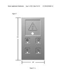
[0046] FIG. 2-b shows a universal electricity utility symbol molded into the invention's finish. The method of design allows other universal utility or service symbols to be added (molded in), as may be required by city building and public safety codes. It also allows for logos of developers, sponsors, retailers, and other groups to be added to the finished product at time of manufacture.
[0047] FIG. 3 represents the "Classic" or "Lapboard/Siding" version of the present invention. Similar in design and manufacture as FIG. 1 and FIG. 2, but different in that the front and sides of this version are designed to look like the lapboard or siding used in home construction exterior finishes. These siding finishes can be made from either smooth, textured, or wood grained molds to match the prevalent type in a particular neighborhood. The top of this version is also different from FIG. 1 and FIG. 2, in that it is designed to look like the peaked and shingled roof of a home. Singles of various style, shape, and texture can be molded into the finished product's design. The molded in decoration or access door of this version is also different from FIG. 1 and FIG. 2 in that the mold is designed to look like horizontal louvers that are often used as attic vents on the exterior of a home. Decorative access doors of different designs and sizes are also included in this invention. This Classic version of the present invention is also designed to be painted or color molded to match or compliment the structure it is attached to. The size and dimensions of the FIG. 3 Classic version are the same or similar to those of the Generic version depicted in FIG. 2.
[0048] FIG. 4 represents the "Brick" version of the present invention. The overall design is similar in size, shape, dimensions and construction method of FIG. 1, and FIG. 2 except that the front and sides of this version are designed with a brick impression. The top is designed with a stucco impression similar to FIG. 1 and FIG. 2. Decorative access doors of different designs and sizes are also included in this invention. This Brick version of the present invention is also designed to be painted or color molded to match or compliment the structure it is attached to. The size and dimensions of the FIG. 4 Brick version are the same or similar to those of the Generic version depicted in FIG. 2.
[0049] FIG. 5 represents the "Stone" version of the present invention. The overall design is similar in size, shape, dimensions, and manufacture method of FIG. 1 FIG. 2 except that the front and sides of this version are designed with a stone impression. The top is designed with a stucco impression similar to FIG. 1 and FIG. 2. Decorative access doors of different designs and sizes are also included in this invention. This Stone version of the present invention is also designed to be painted or color molded to match or compliment the structure it is attached to. The size and dimensions of the FIG. 4 Brick version are the same or similar to those of the Generic version depicted in FIG. 2.
[0050] FIG. 6 represents "Customizable" or "Custom" version of the current invention. It is designed so that individual components of the Generic, Classic, Brick, Stone, and future versions of the invention can be molded and manufactured separately, i.e. top or cap piece, upper body or access door piece, center band, and lower body piece, and then re-arranged in various combinations of the individual components in order to better match the exterior finish of a custom home, apartment building, or office building. The individual pieces are designed to be interlocking so that when assembled it looks and functions as a single unit. The lower body section is designed to telescope vertically inside the upper body piece. The point at which the two body sections intersect is hidden by the center decorative band. As FIG. 6 depicts, the different sections can be interchanged due to the universal design and can be painted or color molded to match or compliment the structure it is attached to. The size and dimensions of the FIG. 6 Custom version is dictated by the size of the service entry point area to be enclosed. For example an apartment or office building may have multiple cable or satellite boxes, along with multiple utility meters in a row, that would require the present invention to be modified (made considerably wider and deeper) to enclose all the service entry points in a manner desired by the customer.
[0051] Referring now to FIG. 7, a centralizing Universal Back Panel of the current invention is depicted with molded impressions to designate placement of utilities such as electricity, phone, television, satellite, internet, solar, etc. This Universal Back Panel is designed to be attached via screws or lag bolts to the framing of a house or building at the time of construction, or before utilities and other service connections are made to the structure. It is made of the same material and method as the Universal Service Enclosure. Its' design allows for any of the Universal Service Enclosures to be attached to it. The current attachment method between the Universal Back Panel and the Universal Service Enclosure is a keyhole method, which allows for quick and easy installation and removal, but may be attached via other methods.
[0052] The advantages of the present invention, without limitation, are addressing the need to centralize and enclose the utility and other services entry points to a home or building into a single organized Universal Service Enclosure, that is easily located, easily accessible, can accommodate future service connections, and matches or complements the overall appearance of the exterior of the home or building which it is attached to. A great deal of time and money is spent designing, and finishing the exterior of a home, apartment building, or office building, in a manner that is both appealing, and one that conforms to the look and feel of the neighborhood, community, development, or area where the structure is built. Somewhere along the building process, utility companies and service companies install their meters, junction boxes, cables and pipes, with little apparent thought for their conformity to the final finish, facade, and overall look with the building they are attached to. With the advances of technology, along with the expansion of internet and digital media access via cable, satellite, and fiber optics, and the growth of residential and small business solar and wind power generation, it is expected that even more service entry points will be added to existing residential and commercial structures. Currently there is no device or centralized access panel and/or enclosure such as the present Universal Service Enclosure, and centralized Universal Back Panel, which can enclose multiple utility and service access or entry points to a home or building while maintaining or complimenting the look of the existing exterior facade and finish of the home or building. The present invention solves this problem by providing the solution of a universal enclosure and/or new construction back panel, which covers existing and future service connections to that building. This invention is modular, durable, easy to attach or remove, can be modified to accommodate various looks, colors, textures, and conforms to, or enhances the look of one's home or building.
[0053] While the foregoing written description of the invention describes a system, design, and method of manufacture of the invention, it is understood that one of modest skill could use other materials or methods to make and use the present invention. The invention should therefore not be limited by the above described embodiment, method, and examples, but by all embodiments and methods within the scope and spirit of the invention as claimed including the conceptualization of the centralizing and universal nature the invention.
User Contributions:
Comment about this patent or add new information about this topic:
Images included with this patent application:
 |  |
 |  |
 |  |
 |  |
| New patent applications in this class: | |
| Date | Title |
|---|---|
| 2022-09-22 | Electronic device |
| 2022-09-22 | Front-facing proximity detection using capacitive sensor |
| 2022-09-22 | Touch-control panel and touch-control display apparatus |
| 2022-09-22 | Sensing circuit with signal compensation |
| 2022-09-22 | Reduced-size interfaces for managing alerts |