Patent application title: ASSEMBLY FOR ANALYZING A LIGHT PATTERN CAUSED BY REFRACTION AND REFLECTION AT A PRECIOUS STONE
Inventors:
Karlheinz Eder (Buch In Tirol, AT)
IPC8 Class: AG01N2187FI
USPC Class:
356 30
Class name: Optics: measuring and testing crystal or gem examination
Publication date: 2016-06-09
Patent application number: 20160161421
Abstract:
The invention relates to an assembly (1) for analyzing a light pattern
(3) caused by refraction and reflection at a precious stone (2),
comprising a light source (4) for illuminating the precious stone (2), a
retaining device (5) for retaining the precious stone (2), an in
particular flat diffusing screen (6) for imaging the light pattern (3),
and a camera (7) for recording the light pattern (3) imaged on the
diffusing screen (6), wherein the assembly (1) comprises a
semi-transmitting optical element (8) for deflecting, in the direction of
the precious stone (2), the light (9) emitted by the light source (4) and
for transmitting the light (10) refracted and reflected at the precious
stone (2).Claims:
1. An assembly for analysing a light pattern caused by refraction and
reflection at a precious stone, the assembly comprising: a light source
for illuminating the precious stone; a holding device for holding the
precious stone; an in particular flat diffusing screen for imaging the
light pattern; and a camera for recording the light pattern imaged on the
diffusing screen, wherein the assembly includes a semi-transmitting
optical element for deflection of the light emitted by the light source
in the direction of the precious stone and transmission of the light
refracted and reflected at the precious stone.
2. An assembly as set forth in claim 1, wherein the semi-transmitting optical element is a semi-transmitting mirror or a glass plate.
3. An assembly as set forth in claim 1, wherein the holding device and the light source are arranged on the same side of the diffusing screen.
4. An assembly as set forth in claim 1, wherein the camera is arranged on the side of the diffusing screen, that is opposite to the holding device, and/or is oriented substantially perpendicularly to the diffusing screen and/or the diffusing screen is a transmission screen.
5. An assembly as set forth in claim 1, wherein the holding device is arranged at a spacing of between 10 cm and 50 cm, preferably at a spacing of about 30 cm, from the diffusing screen.
6. An assembly as set forth in claim 1, wherein the camera includes a CCD chip.
7. An assembly as set forth in claim 1, wherein the light source is an LED light source.
8. An assembly as set forth in claim 1, wherein the light emitted from the light source is unpolarized, and/or has a beam diameter of between 5 mm and 15 mm, preferably a beam diameter of about 10 mm, and/or is collinated, and/or has a half-angle divergence of between 0.1.degree. and 0.4.degree., preferably a half-angle divergence of about 0.25.degree., and/or has a spectrum with a plurality of different wavelengths from the range of visible light.
9. An assembly as set forth in claim 1, wherein the assembly includes an evaluation unit, preferably a computer, for evaluation of the light pattern recorded by the camera.
10. An assembly as set forth in claim 1, wherein at least the light source, the holding device, the diffusing screen, the camera and the semi-transmitting optical element are arranged in an apparatus for suppressing background light.
11. A method of analyzing a light pattern caused by refraction and reflection at a precious stone by means of an assembly as set forth in claim 1, the method comprising the following method steps: i. holding the precious stone to be analyzed in the holding device; ii. illuminating the precious stone by means of the light source; and iii. recording the light pattern imaged on the diffusing screen by means of the camera.
12. A method as set forth in claim 11, wherein method steps ii. and iii. are repeated at least once with a differing illumination time and/or a differing intensity and/or with a differing polarization.
13. A method as set forth in claim 11, wherein evaluation of the light pattern recorded by the camera by means of the evaluation unit is included as a further method step (iv.).
14. A method as set forth in claim 13, wherein an HDR image is produced from at least two light patterns recorded with differing illumination times and/or intensities and/or polarizations.
15. A method as set forth in claim 13, wherein the light pattern recorded by the camera is compared to at least one light pattern stored in the evaluation unit, wherein the stored light pattern is preferably a simulated light pattern.
Description:
[0001] The invention concerns an assembly for analyzing a light pattern
caused by refraction and reflection at a precious stone, comprising a
light source for illuminating the precious stone, a holding device for
holding the precious stone, an in particular flat diffusing screen for
imaging the light pattern, and a camera for recording the light pattern
imaged on the diffusing screen. The invention further concerns a method
of analyzing a light pattern caused by refraction and reflection at a
precious stone by means of the assembly according to the invention.
[0002] An assembly having the specified components is known for example from U.S. Pat. No. 5,828,405. A disadvantage with that assembly in the state of the art is that illumination of the diamond to be investigated is effected by way of an opening in the diffusing screen. The result of this is that the part of the light pattern which would be imaged in the region of that opening on the diffusing screen is lost. In addition, only a small part of the diamond can be illuminated with the illumination arrangement disclosed in U.S. Pat. No. 5,828,405. In that way also there is a loss of information about the diamond.
[0003] And finally there is the further disadvantage that, by virtue of the geometry of the illumination arrangement, it is necessary for the camera for recording the light pattern imaged on the diffusing screen to be arranged at an angle relative to the screen and on the other hand to be positioned relatively close to the diffusing screen. The latter requires the use of an extreme fisheye objective. Overall the arrangement of the camera in relation to the diffusing screen in U.S. Pat. No. 5,828,405 results in severe perspective distortions of the recorded light pattern. Theoretically it would admittedly be possible to increase the distance of the camera relative to the diffusing screen so that the camera is disposed for example at the height of the precious stone or even behind same, but then the free view on to the diffusing screen would be restricted by parts of the illumination arrangement or the precious stone itself, which again would lead to information loss.
[0004] For the sake of completeness however it should also be noted that the aim in U.S. Pat. No. 5,828,405 is to record a characteristic "fingerprint" of a precious stone and to compare it to a fingerprint stored in a database in order to be able to identify the precious stone in the event of theft. As long as the image of the precious stone is always recorded with the same apparatus information losses and perspective distortions do not play any part.
[0005] In contrast thereto the assembly of the present invention is used for analysis of a light pattern caused by refraction and reflection at a precious stone. This for example involves analyzing the quality of a precious stone, which is influenced for example by parameters like geometry or polish. Against the background of that aim the above-mentioned disadvantages do in fact play a definite part.
[0006] It should be noted that the present assembly or the present method in principle can be used for the analysis of all kinds and shapes of precious stones. In particular it is also possible to analyze natural or synthetically produced precious stones and gemstones like for example zirconia or precious stones made from glass (glass stones).
[0007] The object of the present invention is to avoid the disadvantages known from the state of the art and to provide an improved assembly for analyzing a light pattern caused by refraction and reflection at a precious stone and an improved method for same, in which the assembly according to the invention is used.
[0008] That object is attained by the features of independent claims 1 and 11.
[0009] One of the core concepts of the present invention therefore is that the assembly includes a semi-transmitting optical element for deflection of the light from the light source in the direction of the precious stone and transmission of the light refracted and reflected at the precious stone, wherein the semi-transmitting optical element is for example a semi-transmitting mirror or a glass plate.
[0010] One of the essential differences over the state of the art therefore is that the light coupling-in effect is implemented by way of a semi-transmitting optical element. In that way it is possible to more flexibly arrange the elements of the assembly and in that way to avoid the disadvantages known from the state of the art.
[0011] By way of example the holding device for holding the precious stone and the light source for illuminating the precious stone can be arranged on the same side of the diffusing screen. That has the advantage that a hole does not have to be provided in the diffusing screen for illumination of the precious stone. At the same time space is also provided for a substantially perpendicular arrangement of the camera for recording the light pattern imaged on the diffusing screen, relative to the diffusing screen. For that purpose it can be provided that the camera is arranged on the side of the diffusing screen, that is opposite to the holding device, and/or the diffusing screen is a transmission screen. By virtue of such an arrangement of the camera in relation to the diffusing screen it is possible for the spacing of the camera relative to the diffusing screen to be so selected that it is possible to use objectives which result in no or only very slight perspective distortions of the imaged light pattern. In addition it is possible to entirely avoid information losses as there is no longer any need to arrange between the camera and the diffusing screen elements which adversely affect a free view of the camera on to the diffusing screen.
[0012] The apparent disadvantage due to the use of an additional optical element in the form of a semi-transmitting optical element (any optical element is always linked to more or less severely pronounced imaging defects) is therefore more than compensated by a series of advantages.
[0013] In an advantageous configuration of the assembly according to the invention the holding device is arranged at a spacing of between 10 cm and 50 cm, preferably at a spacing of about 30 cm, from the diffusing screen.
[0014] In addition it has proven to be advantageous if the camera includes a CCD chip and/or the light source is an LED light source.
[0015] The light emitted from the light source is preferably unpolarized, and/or has a beam diameter of between 5 mm and 15 mm, preferably a beam diameter of about 10 mm, and/or is collinated, and/or has a half-angle divergence of between 0.1.degree. and 0.4.degree., preferably a half-angle divergence of about 0.25.degree., and/or has a spectrum with a plurality of different wavelengths from the range of visible light. The latter manifests itself in that the precious stone is illuminated substantially with white light which in part is broken down into its spectral colors by refraction at the precious stone so that the light pattern imaged on the diffusing screen includes in part colored light reflections.
[0016] Preferably it is also provided that the assembly according to the invention includes an evaluation unit, preferably a computer, for evaluation of the light pattern recorded by the camera, and/or at least the light source, the holding device, the diffusing screen, the camera and the semi-transmitting optical element are arranged in an apparatus for suppressing background light. The latter measure makes it possible to markedly improve the signal-noise ratio.
[0017] As stated in the opening part of this specification protection is also claimed for a method of analyzing a light pattern caused by refraction and reflection at a precious stone by means of an assembly according to the invention, wherein the method includes the following steps: holding the precious stone to be analyzed in the holding device, illuminating the precious stone by means of the light source and recording the light pattern imaged on the diffusing screen by means of the camera.
[0018] In a particularly preferred embodiment of that method it is provided that method steps 2 and 3 are repeated at least once with a differing illumination time and/or with a differing intensity and/or with a differing polarization (in the case where polarized light is used). As a further consequence it is then more specifically possible--if evaluation of the light pattern recorded by the camera by means of the evaluation unit is included as a further method step--to produce an HDR image with an increased information content from at least two light patterns recorded with differing illumination times and/or intensities and/or polarizations.
[0019] And finally it has proven to be desirable for the light pattern recorded by the camera to be compared to at least one light pattern stored in the evaluation unit, in which case the stored light pattern preferably involves a simulated light pattern. In that way it is possible for example to detect deviations from an ideal cut of the precious stone.
[0020] Further features and advantages of the present invention will be apparent from the Figures and the following specific description. In the Figures:
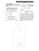
[0021] FIG. 1 shows a diagrammatic view of a preferred embodiment of the assembly,
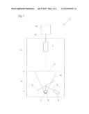
[0022] FIG. 2 shows by way of example a simplified diagrammatic view of a light pattern produced by refraction and reflection at a precious stone and imaged on the diffusing screen, and
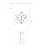
[0023] FIG. 3 shows a flow chart to diagrammatically illustrate a preferred embodiment of the method according to the invention.
[0024] The preferred embodiment as shown in FIG. 1 of the assembly 1 according to the invention for analyzing a light pattern caused by refraction and reflection at a precious stone includes a light source 4 for illuminating a precious stone 2 held in a holding device 5. In that case an LED light source is used as the light source 4. The light from the light source 4--the corresponding optical axis is denoted by reference 9--is unpolarized, it is of a beam diameter of about 10 mm, it is collinated and it has a half-angle divergence of about 0.25.degree. as well as a spectrum with a plurality of different wavelengths from the range of visible light. Most commercially usual precious stones can be completely illuminated by virtue of the magnitude of the beam diameter.
[0025] The light 9 issuing from the light source 4 is initially incident at an angle on a semi-transmitting optical element 8 in the form of a semi-transmitting mirror and is reflected at the surface, that is towards the light source, of the semi-transmitting optical element 8. More precisely the light is deflected in the direction of the precious stone 2. In that case a part of the light incident on the precious stone 2 is immediately reflected in the direction of the diffusing screen 6. The remaining part--which is much greater--of the light passes into the precious stone 2, is refracted there and experiences total reflections at the surfaces of the faceted precious stone 2 until finally it issues from the precious stone 2 again in the direction of the diffusing screen 6. Naturally a part of the light also leaves the precious stone 2 in a direction away from the diffusing screen 6 and is thus "lost" in regard to the light pattern.
[0026] The refracted and reflected light 10 issuing from the precious stone 2 to be analyzed--being indicated by the broken lines--passes in a transmission mode through the semi-transmitting optical element 8 and is then incident on the diffusing screen 6 on which a diffusion image which is characteristic in accordance with the respective kind of the precious stone 2 is imaged. The spacing of the holding device 5 and thus (approximately the center) of the precious stone 2 relative to the diffusing screen 6 is about 30 cm.
[0027] As can be seen from the structure of the assembly 1 as shown in FIG. 1 the holding device 5 and the light source 4 are arranged on the same side of the diffusing screen 6.
[0028] The diffusing screen 6 is a transmission screen, that is to say the light pattern imaged on the diffusing screen 6 is also visible on the side of the diffusing screen 6, that is away from the holding device 5. In that way it is possible for the light pattern imaged on the diffusing screen 6 to be recorded by means of a camera 7 arranged on the side of the diffusing screen 6, that is opposite to the holding device 5. In addition it is also possible for the camera 7 to be oriented in its longitudinal extent substantially perpendicularly to the diffusing screen 6, as indicated by the dash-dotted line. The camera 7 is a CCD camera with a corresponding CCD chip.
[0029] The light source 4, the holding device 5, the diffusing screen 6, the camera 7 and the semi-transmitting optical element 8 are arranged in an apparatus 13 for suppressing background light, the walls of the apparatus 13 having a black matt surface.
[0030] The camera 7 is connected to an evaluation unit 12 in the form of a computer by way of a suitable data line 15 which can also be of a wireless nature.
[0031] FIG. 2 is a black-and-white illustration by way of example illustrating a light pattern 3 produced by refraction and reflection at a precious stone and imaged on the diffusing screen. That light pattern 3 is composed of individual light flecks 16, those light flecks 16 being produced by refraction and reflection characteristically for each precious stone. It should be noted that the image shown in FIG. 2 is a false color image with inverted luminosity. The white regions are in reality black, that is to say no light reaches here, and the dark regions are those regions of the diffusing screen, on which light is incident. Due to the simplified black-and-white illustration it is also not possible to see that the light flecks 16 in part have a color pattern which is similar to the breakdown of white light by a prism. It should also be noted that the light flecks 16 can be of a differing luminosity. In the English-language literature such a light pattern of a precious stone is frequently also referred to as its "fire".
[0032] FIG. 3 shows a flow chart illustrating a preferred embodiment of the method 14 according to the invention: in a first step i. a precious stone to be analyzed is held in the holding device. In a subsequent method step ii. illumination of the precious stone is effected by means of the light source. In a third method step iii. the light pattern imaged on the diffusing screen is recorded by means of the camera. Method steps ii. and iii. are then repeated with a series, for example ten, of differing illumination times, ranging for example between about 60 ms and about 16000 ms, that is to say a plurality of light patterns which are produced with differing illumination times are successively recorded by means of the camera.
[0033] In a further method step iv. evaluation of the light pattern recorded by the camera is effected by means of the evaluation unit. For that purpose an HDR image (high dynamic range) is firstly produced from the light patterns recorded with differing illumination times and then compared to a light pattern which is stored in the evaluation unit and which is a simulated light pattern. On the basis of that comparison it is possible to draw conclusions about the quality of the precious stone.
User Contributions:
Comment about this patent or add new information about this topic:
Images included with this patent application:
 |  |
 |
| New patent applications in this class: | |
| Date | Title |
|---|---|
| 2017-08-17 | Mobile gemstone identification |
| 2016-05-19 | Method and device for gemstone evolution |
| 2016-05-05 | Method of measuring characteristics of crystal unit |
| 2016-04-21 | Examination method for distinguishing between natural diamond and synthetic cvd/hpht diamonds |
| 2016-04-21 | Examination method to apprais corundum that has undergone beryllium diffusion treatment |
| New patent applications from these inventors: | |
| Date | Title |
|---|---|
| 2012-09-13 | Gemstone with a chaton cut |
| 2012-04-05 | Gem with brilliant cut |
| Top Inventors for class "Optics: measuring and testing" | |
| Rank | Inventor's name |
|---|---|
| 1 | Robert E. Bridges |
| 2 | Yuta Urano |
| 3 | Glen A. Sanders |
| 4 | Zhiyong Li |
| 5 | Akira Hamamatsu |