Patent application title: EXHAUSTING DEVICE
Inventors:
Rong Fung Huang (Taipei City, TW)
Rong Fung Huang (Taipei City, TW)
IPC8 Class: AF24C1520FI
USPC Class:
126299 D
Class name: Stoves and furnaces stove hoods stove surface ventilation only
Publication date: 2016-06-09
Patent application number: 20160161129
Abstract:
An exhaust device comprises an air-extraction hood and a left upright
plate and a right upright plate that are respectively placed below two
lateral sides of the air-extraction hood, where a first guiding part is
provided at the front end of the right lateral surface of the left
upright plate and a left top plate is provided between the first guiding
plate and an air-extraction slot; a second guiding part is provided at
the front end of the left lateral surface of the right upright plate and
a right top plate is provided between the second guiding plate and the
air-extraction slot; and the right top plate and the left top plate are
symmetrically arranged at two sides of the bottom of the air-extraction
hood. The leakage of pollutants can be prevented by means of the
cooperation of the air-extraction slot and an air-blowing slot.Claims:
1. An exhausting device, comprising an air-extraction hood, a left
upright plate and a right upright plate, where a bottom of the
air-extraction hood is provided with at least one air-extraction slot and
the air-extraction slot is connected to an air-extraction device for
drawing air upwards; the left upright plate and the right upright plate
are respectively placed below a left side and a right side of the
air-extraction hood; and a space is formed between the air-extraction
hood, the left upright plate and the right upright plate; wherein a side
or a surface of the air-extraction hood, the left upright plate, and the
right upright plate that is approaching towards a user is defined as a
front end, while a side or a surface of the air-extraction hood, the left
upright plate, and the right upright plate that is away from the user in
an opposite direction is defined as a rear end; and two sides of the
air-extraction hood, the left upright plate, and the right upright plate
are respectively defined as a left side and a right side when the user
faces the air-extraction hood, the left upright plate, and the right
upright plate; the exhausting device characterized in that: an elongate
and upright first guiding part is provided at a front end of a right
lateral surface of the left upright plate, a left top plate is provided
between the first guiding part and the air-extraction slot, and the left
top plate has a top side upwardly adjacent to a left side of a bottom of
the air-extraction hood and has a left side leftwardly adjacent to the
right lateral surface of the left upright plate; an elongate and upright
second guiding part is provided at a front end of a left lateral surface
of the right upright plate, a right top plate is provided between the
second guiding part and the air-extraction slot, and the right top plate
has a top side upwardly adjacent to a right side of the bottom of the
air-extraction hood and has a right side rightwardly adjacent to the left
lateral surface of the right upright plate; and a left air blow groove
and a right air blow groove are provided on the bottom of the
air-extraction hood and are respectively in elongate shape for blowing
air downwardly, where the left air blow groove and the right air blow
groove are aligned with and are spaced from each other; the left air blow
groove is parallel to the top side of the left top plate and located at a
rear end of the top side of the left top plate; and the right air blow
groove is parallel to the top side of the right top plate and located at
a rear end of the top side of the right top plate.
2. The exhausting device as claimed in claim 1, further comprising a first upright plate and a second upright plate, wherein the first upright plate is bended and extended leftwardly from the front end of the left upright plate, and the second upright plate is bended and extended rightwardly from the front end of the right upright plate.
3. The exhausting device as claimed in claim 1, wherein the left top plate and the right top plate are symmetrical to each other, and the left top plate has one end that extends rightwardly while not exceeds the air-extraction slot's left edge, and the right top plate has one end that extends leftwardly while not exceeds the air-extraction slot's right edge.
4. The exhausting device as claimed in claim 1, wherein the left top plate is an inverted triangle plate.
5. The exhausting device as claimed in claim 1, wherein the right top plate is an inverted triangle plate.
6. The exhausting device as claimed in claim 1, wherein the air-extraction slot is in elongate shape, and the left air blow groove and the right air blow groove are parallel to the air-extraction slot.
7. The exhausting device as claimed in claim 1, further comprising a rear plate, wherein the rear plate has a left end and a right end that are respectively connected with rear ends of the left upright plate and the right upright plate.
Description:
TECHNICAL FIELD
[0001] The present invention relates to an exhausting device, and more particularly, to an exhausting device capable of effectively preventing the leakage of soot pollutants and suitable for factories, laboratories, and kitchens.
BACKGROUND
[0002] A "conventional range hood" scarcely differs from a ceiling-mounted range hood in a working space. The flange of this kind of range hood may be in a flat shape, a downward arc shape, or in a box-shape, and the air-extraction opening may be in a round shape, a square shape, a rectangular shape, or in an elongate shape. When this kind of range hood draws air, the air and pollutants would flow into the space below the hood from the edge of the flange, then be drawn into the air-extraction opening, and afterwards the air and pollutants would be exhausted outside through ducts. In this case, the air flow rate at a location near the air-extraction opening is much higher, while the air flow velocity at a location away from the air-extraction opening would decrease rapidly with the increase of the distance from the air-extraction opening. The upward force of air-extraction would be insufficient because the upward airflow velocity becomes slow within short distance below the air-extraction opening. It is easily affected by interference flow resulted from the draft in the environment, people walking or the operation of fans and air conditioners, and thus soot and pollutants would diffuse or disperse with the interference flow.
[0003] When above range hood is used in high-temperature gas-production environments, the speed of updraft would increase due to the higher buoyant effect resulted from high temperature of fire and oil. However, soot and pollutants would diffuse out easily from the front and the lateral sides of the range hood because of turbulent diffusion and expansion effect caused by the high temperature. Therefore, for a conventional range hood, it would enhance the force of air-extraction in order to improve the air-extraction capacity. However, in this case, it would not only increase the noise and waste the energy, but it is also unable to prevent the leakage completely.
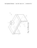
[0004] As for above problems, a common improvement is made as shown in FIG. 11, where baffles were added respectively in the left side, right side, and the rear of the range hood (a). However, when in implementation, the boundary layers of flow are easily departed at the front edge of both side plates (b), so as to produce a large re-circulation bubble (c) respectively. Soot pollutants would be swept by this large re-circulation bubble (c) to the front edge of both side plates (b) nearby and leaked out as a result of molecular diffusion and turbulent diffusion, or they would be swept to external environment as a result of the effect of the interference flow in the environment. Besides, complicated three dimension vortexes and strong turbulences would be induced at the cross of the flange (d) and the side plate (b) of the range hood (a) as a result of the three-dimensional effect. In this case, soot pollutants would also be swept to the cross of the flange (d) and the side plate (b) of the range hood (a) to cause leakage. For this reason, it is unable to achieve the effect of preventing leakage completely simply by adding side plates (b) respectively in the left and right side of the range hood (a).
SUMMARY OF THE DISCLOSURE
[0005] In view of this, in order to provide a structure distinct from conventional ones and in order to improve above shortcomings, the inventor had developed the present invention after years of experiences and nonstop research and improvements.
[0006] An object of the present invention is to provide an exhausting device that is provided with a first and a second guiding part respectively at front ends of the left and right upright plates, where a left top plate is provided between the first guiding part and the air-extraction slot, while a right top plate is provided between the second guiding part and the air-extraction slot, so as to solve the problem of three dimensional vortexes and strong turbulences that are produced at the cross of the flange and the side plate of the conventional range hood, and then to keep the air vortexes away from the frontal opening of the exhausting device to prevent the leakage of pollutants.
[0007] In order to achieve above object, the present invention provides an exhausting device comprising an air-extraction hood, a left upright plate, a right upright plate, a first guiding part, a second guiding part, a left top plate, and a right top plate. A bottom of the air-extraction hood is provided with at least one air-extraction slot and the air-extraction slot is connected to an air-extraction device for drawing air upwards. The left upright plate and the right upright plate are respectively placed below a left side and a right side of the air-extraction hood. A space is formed between the air-extraction hood, the left upright plate, and the right upright plate. A side or a surface of the air-extraction hood, the left upright plate, and the right upright plate that is approaching towards a user is defined as a front end, while a side or a surface of the air-extraction hood, the left upright plate, and the right upright plate that is away from the user in an opposite direction is defined as a rear end. Two sides of the air-extraction hood, the left upright plate, and the right upright plate are respectively defined as a left side and a right side when the user faces the air-extraction hood, left upright plate, and right upright plate. The exhausting device is characterized in that: an elongate and upright first guiding part is provided at a front end of a right lateral surface of the left upright plate, a left top plate is provided between the first guiding part and the air-extraction slot, and the left top plate has a top side upwardly adjacent to a left side of a bottom of the air-extraction hood and has a left side leftwardly adjacent to the right lateral surface of the left upright plate; an elongate and upright second guiding part is provided at a front end of a left lateral surface of the right upright plate, a right top plate is provided between the second guiding part and the air-extraction slot, and the right top plate has a top side upwardly adjacent to a right side of the bottom of the air-extraction hood and has a right side rightwardly adjacent to the left lateral surface of the right upright plate; and a left air blow groove and a right air blow groove are provided on the bottom of the air-extraction hood and are respectively in elongate shape for blowing air downwardly, where the left air blow groove and the right air blow groove are aligned with and spaced from each other; the left air blow groove is parallel to the top side of the left top plate and located at a rear end of the top side of the left top plate; and the right air blow groove is parallel to the top side of the right top plate and located at a rear end of the top side of the right top plate.
[0008] In implementation, the present invention further comprises a first upright plate and a second upright plate, wherein the first upright plate is bended and extended leftwardly from the front end of the left upright plate, and the second upright plate is bended and extended rightwardly from the front end of the right upright plate.
[0009] In implementation, the left top plate and the right top plate are symmetrical to each other, and the left top plate has one end that extends rightwardly while not exceeds the air-extraction slot's left edge, and the right top plate has one end that extends leftwardly while not exceeds the air-extraction slot's right edge.
[0010] In implementation, the left top plate and the right top plate are respectively an inverted triangle plate.
[0011] In implementation, the air-extraction slot is in elongate shape, and the left air blow groove and the right air blow groove are parallel to the air-extraction slot.
[0012] In implementation, the present invention further comprises a rear plate, wherein the rear plate has a left end and a right end that are respectively connected with rear ends of the left upright plate and the right upright plate.
[0013] The following detailed description, given by way of examples or embodiments, will best be understood in conjunction with the accompanying drawings.
BRIEF DESCRIPTION OF THE DRAWINGS
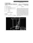
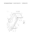
[0014] FIG. 1 is a perspective view showing a first embodiment of the present invention.
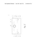
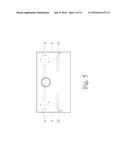
[0015] FIG. 2 is a top view showing the first embodiment of the present invention.
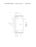
[0016] FIG. 3 is a front view showing the first embodiment of the present invention.
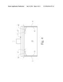
[0017] FIGS. 4.about.5 show the use of the first embodiment of the present invention.
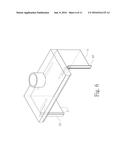
[0018] FIG. 6 is a perspective view showing a second embodiment of the present invention.
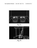
[0019] FIG. 7a shows a schematic view where edible oil in a pan is heated to produce great amount of soot and Laser-light sheet is used for illuminating the horizontal plane of the device according to the present invention to show the movement of the soot with the airflow.
[0020] FIG. 7b shows a schematic view where Laser-light sheet is used for illuminating the vertical plane of the device according to the present invention to show the movement of the soot with the airflow.
[0021] FIG. 8 shows the results of the velocity distribution along the horizontal plane of the flow field, where the velocity is measured by using laser Doppler velocimeter.
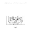
[0022] FIGS. 9a and 9b respectively show the flow fields of the airflow along the vertical planes in the device of the present invention and a conventional range hood, where in both figures a mannequin is present in front of the device according to the present invention and the conventional range hood to simulate the operation of a cook.
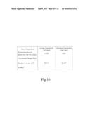
[0023] FIG. 10 shows the experimental results of the leakage concentration of SF.sub.6 gas in view of FIGS. 9a and 9b.
[0024] FIG. 11 shows the use of a conventional range hood.
DETAILED DESCRIPTION
[0025] Please refer to FIGS. 1-3 showing a first embodiment of an exhausting device comprising an air-extraction hood 2, a left upright plate 3, a first guiding part 31, a left top plate 32, a right upright plate 4, a second guiding part 41, a right top plate 42, and a rear plate 5. A side or a surface of the air-extraction hood 2, the left upright plate 3, and the right upright plate 4 that is approaching towards a user is defined as a front end, while a side or a surface thereof that is away from the user in an opposite direction is defined as a rear end. Two sides of the air-extraction hood 2, the left upright plate 3, and the right upright plate 4 are respectively defined as a left side and a right side when the user faces the air-extraction hood 2, left upright plate 3, and right upright plate 4.
[0026] The bottom of the air-extraction hood 2 is provided with an air-extraction slot 21. The air-extraction slot 21 is generally in elongate shape and the elongate air-extraction slot 21 is parallel to the rear end surface of the air-extraction hood 2. In implementation, the bottom of the air-extraction hood 2 may be provided with one or more air-extraction slots 21 that are in a round shape, a square shape, or a rectangular shape. The air-extraction hood 2 has a top end provided with an air-exhausting port 22 that is connected to an air-extraction device (such as a blower), so as to draw air upwardly outside the air-exhausting port 22 when the air-extraction device is in operation. Furthermore, the bottom of the air-extraction hood 2 is provided with a left air blow groove 23 and a right air blow groove 24 that are respectively in elongate shape. The left air blow groove 23 and the right air blow groove 24 are aligned with and spaced from each other. Besides, the left air blow groove 23 and the right air blow groove 24 are parallel to the air-extraction slot 21, and the left air blow groove 23 and the right air blow groove 24 are connected to an air-supplying device (such as a cross flow fan) to blow air downwardly.
[0027] The left upright plate 3, the right upright plate 4, and the rear plate 5 are respectively a rectangular plate. The left upright plate 3 and the right upright plate 4 are respectively placed below the left side and the right side of the air-extraction hood 2. The left end and the right end of the rear plate 5 are respectively connected with the rear end of the left upright plate 3 and the rear end of the right upright plate 4. A space 25 is formed between the air-extraction hood 2, the left upright plate 3, the right upright plate 4, and the rear plate 5, and an opening is formed in front of the space 25.
[0028] The first guiding part 31 and the second guiding part 41 are respectively in elongate and upright shape. The left lateral surface of the first guiding part 31 is attached to the front end of the right lateral surface of the left upright plate 3. The right lateral surface of the second guiding part 41 is attached to the front end of the left lateral surface of the right upright plate 4. Besides, the horizontal cross-sections of the first and second guiding parts 31, 41 are in a semi-circular shape. In implementation, the horizontal cross-sections of the first and second guiding parts 31, 41 also could be in a curved shape to perform the function of guiding airflow.
[0029] The left top plate 32 and the right top plate 42 are respectively an inverted triangle plate. The left top plate 32 and the right top plate 42 are symmetrically provided at the two sides of the bottom of the air-extraction hood 2. The left top plate 32 is provided between the first guiding part 31 and the air-extraction slot 21, while the right top plate 42 is provided between the second guiding part 41 and the air-extraction slot 21. Specifically, the left top plate 32 has a top side 321 upwardly adjacent to a left side of the bottom of the air-extraction hood 2 and has a left side 322 leftwardly adjacent to the right lateral surface of the left upright plate 3, and the right top plate 42 has a top side 421 upwardly adjacent to a right side of the bottom of the air-extraction hood 2 and has a right side 422 rightwardly adjacent to the left lateral surface of the right upright plate 4. The top side 321 of the left top plate 32 is parallel to the left air blow groove 23 and located at the front end of the left air blow groove 23. The top side 421 of the right top plate 42 is parallel to the right air blow groove 24 and is located at the front end of the right air blow groove 24.
[0030] The left top plate 32 is extended rightwardly in a direction away from the left upright plate 3 and the right top plate 42 is extended leftwardly in a direction away from the right upright plate 4. In this case, the rightwardly extending end of the left top plate 32 does not exceed the left edge of the air-extraction slot 21, while the leftwardly extending end of the right top plate 42 does not exceed the right edge of the air-extraction slot 21. In implementation, the left top plate 32 and the right top plate 42 also can be plates that are in curved, rectangular, or other shapes while have the flow-guiding function.
[0031] As shown in FIG. 4, it shows the state of the airflow passing by the left top plate 32 and the right top plate 42. In this case, when the airflow flows into the space 25 through the cross of the air-extraction hood 2 and the left upright plate 3 and the right upright plate 4, the re-circulation bubble that is formed as a result of the three-dimensional effect as shown in FIG. 5 would disappear. Thereby, as shown in FIG. 4, the airflow could flow respectively along the left top plate 32 and the right top plate 42, and depart at the edges of the rear ends of the left top plate 32 and the right top plate 42, so as to form respectively a vortex (C, C'), where the vortexes (C, C') are far away from the front side of the space below the air-extraction hood 2. In addition, the left air blow groove 23 and the right air blow groove 24 are respectively placed at the rear ends of the left top plate 32 and the right top plate 42. Thereby, the formed vortexes (C, C') that depart from the edges of the rear ends of the left top plate 32 and the right top plate 42 would be guided into the air-extraction slot 21 by the air blown downwardly from the left air blow groove 23 and the right air blow groove 24, so as to prevent the leakage of soot pollutants from the cross of the air-extraction hood 2 and the left upright plate 3 and the right upright plate 4. Moreover, owing to the guidance of the first guiding plate 31 and the second guiding plate 41, the air blown downwardly from the left air blow groove 23 and the right air blow groove 24 could perform the guidance function more effectively.
[0032] As shown in FIG. 5, when the air outside the left upright plate 3 and the right upright plate 4 is drawn into the space 25 respectively from the locations near the front ends of the left upright plate 3 and the right upright plate 4 via the opening of the space below the air-extraction hood 2, the drawn-in air would flow respectively along the first guiding part 31 and the second guiding part 41. The boundary layers of the airflow would respectively separate at the curved edges of the first guiding part 31 and the second guiding part 41, and then flow further rearwardly to form vortexes (A, A') respectively. These vortexes (A, A') are respectively formed in rear of the first guiding part 31 and the second guiding part 41, and are far away from the opening of the space below the air-extraction hood 2. Thereby, the soot pollutants would not flow backwardly with these vortexes (A, A') along the original entrance path, so that the leakage of the soot pollutants can be prevented.
[0033] As shown in FIG. 6, it shows a second embodiment of an exhausting device according to the present invention. The second embodiment differs from the first embodiment in that: the exhausting device in the second embodiment further comprises a first upright plate and a second upright plate that are rectangular plates, where the first upright plate is bended and extended leftwardly from the front end of the left upright plate, and the second upright plate is bended and extended rightwardly from the front end of the right upright plate. Thereby, air can be guided more smoothly into the space 25 below the air-extraction hood 2.
[0034] Experiments are conducted on the first embodiment of the exhausting device according to the present invention by National Taiwan University of Science and Technology (NTUST) and the experimental results are as follows:
[0035] 1. That the principle, the produced flow field, and excellent performance (effect) of the present invention are proved by these experiments. These experiments are classified into three groups. (1) In the first group, laser-light sheet is used to illuminate the soot, so as to observe the dispersion behavior of the soot in the flow field. (2) In the second group, laser Doppler velocimeter is used to measure the velocity distribution in the flow field. (3) In the third group, two metal hot plates heated to 360.degree. C. by an electric heating wire are provided on the countertop and SF.sub.6 gas is released over these metal hot plates. A mannequin is provided in front of the countertop and the escaping concentrations of the SF.sub.6 gas around the range hood and the nose of the mannequin are measured.
[0036] 2. As shown in FIG. 7a, edible oil in a pan is heated to produce great amount of soot.
[0037] Laser-light sheet is used to illuminate the horizontal plane of the device according to the present invention to show the movement of the soot with the airflow. Four vortexes every two of which are in counter rotation are shown in the horizontal plane. No soot is present outside these vortexes, which indicates that the soot is entirely entrapped in these four vortexes instead of being diffused outside the vortexes. FIG. 7b shows the movement of the soot with the airflow when laser-light sheet is used to illuminate the vertical plane of the device according to the present invention. It shows that the soot moves upwardly and rearward-tilted, and thus it is far away from the front side of the exhausting device. Therefore, as shown in FIGS. 7a and 7b, the exhausting device according to the present invention is capable of causing the upwardly-moving airflow below the air-extraction hood to form "four rearwardly-tilted vortex columns".
[0038] 3. FIG. 8 shows the results of the velocity distribution along the horizontal plane of the flow field, where the velocity is measured by using laser Doppler velocimeter. Along the horizontal plane below the air-extraction hood, the airflow has boundary-layer separation phenomenon when it passes by the front ends of the left and right lateral plates, so as to form two corner vortexes respectively at the internal sides of the left and right lateral plates. The left corner vortex N.sub.c1 rotates counterclockwise, while the right corner vortex N.sub.c2 rotates clockwise. In other words, these two corner vortexes are in counter rotation. Because the air extraction is operated by means of the elongate air-extraction slot, airflow is "relatively two-dimensionally" extracted from the front of the range hood towards the rear thereof. This airflow extracted from the front towards the rear would cooperate with the two corner vortexes N.sub.c1 and N.sub.c2. Based on the principle of flow topology, four vortexes of two pairs N.sub.1, N.sub.2, N.sub.3, N.sub.4 are formed in the central region, where every two vortexes are in counter rotation. Since every two vortexes of the four vortexes (N.sub.1, N.sub.2, N.sub.3, N.sub.4) are in counter rotation and the four vortexes are confined by the lateral plates and the rear wall, it is able to form stable air columns (or hurricanes). Because of the Coanda effect of the rear wall and the location of the elongate air-extraction slot that is arranged towards the rear of the air-extraction hood, the four vortexes every two of which are in counter rotation would be rearwardly tilted. Because the pressure inside the vortexes is lower than that outside the vertexes, the soot would be entrapped into the vortexes and carried upwards by the four vortexes every two of which are in counter rotation and gradually rearwardly-tilted during the upward movement. Finally, it would be extracted into the elongate air-extraction slot. This flow field carrying the soot is stable itself because of the four vortexes every two of which are in counter rotation. Besides, its stability is even enhanced as a result of the fact that it is confined within the space formed between the right and left lateral plates and the rear wall, so that it is more difficult for the soot to diffuse and disperse. Moreover, because of the Coanda effect and the rearwardly-tilted flow path produced by the rearwardly-arranged elongate air-extraction slot, the soot would be much far away from the front opening of the space below the air-extraction hood, so as to reduce greatly the influence caused by the operation of users (such as the cocking of a cock) and interfering draft.
[0039] 4. In order to demonstrate the advantage of the rearwardly-tilted flow field, FIGS. 9a and 9b are used to show respectively the flow fields of airflow along the vertical planes in the device of the present invention and in a conventional range hood. FIG. 9a shows the flow field along the vertical plane of the exhausting device according to the present invention, where a mannequin is placed in front of the exhausting device. The flow pattern of the soot in this figure is similar to what is shown in FIG. 7b, that is, the flow pattern is rearwardly-tilted. FIG. 9b shows the flow field along the vertical plane of a conventional range hood, where a cock (mannequin) stands in front of the range hood. The conventional range hood has two openings on the surface facing downwards, and an air-drawing fan is disposed above each opening. As shown in FIG. 9b, when the cook (mannequin) is cooking in front of the countertop located under the conventional range hood, the airflow would be drawn from the back of the cook towards the up-front area thereof. When the airflow bypasses the cook, a re-circulation bubble or wake would occur in front of the chest of the cook, which is the common phenomenon according to the principle of the fluid dynamics. The airflow that is drawn by the fan of the range hood is moved from the back of the cock to bypass the body of the cock in a similar way in which airflow bypasses a bluff body. According to the flow speed, the width of the human body, and the viscosity coefficient of the fluid, re-circulation bubble or vortex shedding would occur in front of the chest of the cock. The re-circulation bubble or vortex shedding will carry the soot produced above the countertop to the chest of the cock, which would further cause turbulent diffusion and dispersion. Consequently, the soot would easily leak out.
[0040] 5. Above experimental results are obtained by using flow-field visualization technique and laser Doppler velocimeter. As shown in FIG. 10, the data listed in the table shows the results measured by NTUST, where two metal hot plates heated to 360.degree. C. by using electric coils are placed on the countertop and SF.sub.6 gas is released over the metal hot plates. A mannequin is provided in front of the counter. The escaping concentrations of the SF.sub.6 gas around the range hood and in the nose of the mannequin are measured. This measurement is taken for 10 minutes. In the table of FIG. 10, C.sub.ave represents the average concentration measured at the nose of the mannequin for 10 minutes and C.sub.max represents the instantaneous maximum value in 10 minutes. As the results of the escaping concentrations of the SF.sub.6 gas in the table of FIG. 10 indicate, the use of the exhausting device according to the present invention can effectively reduce the escaping concentration, even to a non-detectable level. In contrast, serious leakage is detected in the case of the conventional range hood. In other words, the results of the escaping concentrations of the SF.sub.6 gas accord with the observation obtained by using flow visualization technique.
[0041] Therefore, the present invention has following advantages:
[0042] 1. The present invention provides an exhausting device where the front ends of the left and right upright plates are respectively provided with a first guiding part and a second guiding part while the two sides of the bottom of the air-extraction hood are respectively provided with a left top plate and a right left plate. Thereby, it is able to prevent effectively the three dimensional vortexes and strong turbulences produced by the airflow at the cross of the flange and the side plate of the exhausting device and further to prevent effectively the leakage of pollutants around the left and right lateral corners of the front ends of the air-extraction hood.
[0043] 2. The present invention provides an exhausting device where the front ends of the left and right upright plates are respectively provided with a first guiding part and a second guiding part, the two sides of the bottom of the air-extraction hood are respectively provided with a left top plate and a right left plate, and the bottom of the air-extraction hood is provided with a left air blow groove and a right air blow groove. Thereby, it is able to have the produced vortexes moved far away from the frontal opening of the exhausting device and guided into the air-extraction slot, so as to prevent the leakage of soot pollutants along the original entrance path.
[0044] As disclosed in the above description and attached drawings, the present invention provides an exhausting device that is able to reduce effectively the diffusion of soot pollutants, and is especially capable of preventing the leakage of pollutants around the left and right lateral corners of the front ends of the air-extraction hood. It is new and can be put into industrial use.
[0045] Although the embodiments of the present invention have been described in detail, many modifications and variations may be made by those skilled in the art from the teachings disclosed hereinabove. Therefore, it should be understood that any modification and variation equivalent to the spirit of the present invention be regarded to fall into the scope defined by the appended claims.
User Contributions:
Comment about this patent or add new information about this topic:
Images included with this patent application:
 |  |
 |  |
 |  |
 |  |
 |  |
 |
| Similar patent applications: | |
| Date | Title |
|---|---|
| 2015-11-26 | Soot-exhausting device |
| 2022-05-05 | Exhaust device |
| 2014-03-20 | Defrosting device |
| 2014-04-24 | Heating device |
| 2014-09-11 | Heating device |
| New patent applications in this class: | |
| Date | Title |
|---|---|
| 2017-08-17 | Noise reduction in cooking system |
| 2016-07-14 | Calibration and monitoring of a kitchen hood system |
| 2016-06-23 | Extraction hood |
| 2016-06-02 | Cooling and exhaust system for a cooking oven |
| 2016-05-12 | Oven range ventilator with microwave compartment |
| New patent applications from these inventors: | |
| Date | Title |
|---|---|
| 2015-12-24 | Intelligent air curtain fume hood |
| 2012-11-01 | Exhaust device having deflection plates |
| 2012-06-21 | Range hood capable of resisting draft |
| 2011-05-19 | Reverse oblique air curtain exhaust cabinet |
| Top Inventors for class "Stoves and furnaces" | |
| Rank | Inventor's name |
|---|---|
| 1 | Paul Bryan Cadima |
| 2 | David Deng |
| 3 | Andrew Plotkin |
| 4 | Peter Emery Von Behrens |
| 5 | Derek W. Schrock |