Patent application title: Child-Resistant Closure
Inventors:
Peter A. Piscopo (Medford, NJ, US)
Peter A. Piscopo (Medford, NJ, US)
Assignees:
PLASTEK INDUSTRIES, INC.
IPC8 Class: AB65D5004FI
USPC Class:
53490
Class name: Closing a preformed, freestanding, rigid or semi-rigid container (e.g., box, carton, bottle) by applying a separate preformed closure (e.g., lid, cap) by screwing closure on container
Publication date: 2016-06-09
Patent application number: 20160159533
Abstract:
A child-resistant closure has an inner member and an outer member
encircling the inner member for gripping by a user. The outer member
comprises a sidewall bearing a first engagement feature and an upper web
underside bearing a second engagement feature. The inner member
comprises: an inner sidewall bearing an internal thread for engaging the
container body; an outer sidewall spaced-apart from the inner sidewall
and bearing a third engagement feature, the third engagement feature
engagable to the first engagement feature responsive to an upward
movement of the outer member so as to allow the outer member to transmit
a removal rotation to the inner member. An upper web joins the inner
sidewall and outer sidewall and has an upper surface bearing a fourth
engagement feature engagable to the second engagement feature to transmit
an installing rotation to the inner member.Claims:
1. A child-resistant closure for closing an externally threaded neck of a
container body, the cap comprising: an inner member having an internal
thread for engaging the neck external thread; and an outer member
encircling the inner member for gripping by a user, wherein: the outer
member comprises: a sidewall bearing a first engagement feature; and an
upper web having an underside bearing a second engagement feature; and
the inner member comprises: an inner sidewall bearing the internal
thread; an outer sidewall spaced-apart from the inner sidewall and
bearing a third engagement feature, the third engagement feature
engagable to the first engagement feature responsive to an upward
movement of the outer member so as to allow the outer member to transmit
a removal rotation to the inner member; and an upper web joining the
inner sidewall and outer sidewall and having an upper surface bearing a
fourth engagement feature, the fourth engagement feature engagable to the
second engagement feature to transmit an installing rotation to the inner
member.
2. The child-resistant closure of claim 1 wherein: the outer member upper web has a central aperture exposing the inner member upper web.
3. The child-resistant closure of claim 1 wherein: the first engagement feature comprises one or more gaps in a radially inwardly projecting feature of the outer member sidewall.
4. The child-resistant closure of claim 1 wherein: the inner member is formed as a first single-piece plastic molding; and the outer member is formed as a second single-piece plastic molding.
5. The child-resistant closure of claim 1 wherein: the outer member sidewall first engagement feature comprises at least one gap in a radially inwardly projecting bead; and the inner member outer sidewall third engagement feature comprises at least one downward projection from the inner member outer sidewall.
6. The child-resistant closure of claim 5 wherein: the outer member upper web second engagement feature comprises a first plurality of barbs; and the inner member upper web fourth engagement feature comprises a second plurality of barbs.
7. The child-resistant closure of claim 6 wherein: the first plurality of barbs and second plurality of barbs are positioned to engage each other during installation and angled so that an installing torque drives the outer member downward into firmer engagement with the inner member thus requiring the user to provide no downward pressure to install.
8. The child-resistant closure of claim 7 wherein: the first plurality of barbs and second plurality of barbs have surfaces angled so that an uninstalling rotation of the outer member causes the surfaces to cam against each other lifting the outer member up and out of driving engagement with the inner member.
9. A container comprising: the child-resistant closure of claim 1; and a container body having an externally threaded neck engaged to the inner member internal thread.
10. A method for using the container of claim 9, the method comprising: upwardly pulling the outer member sidewall; and rotating the outer member sidewall in a direction to unscrew the internal thread from the external thread.
11. The method of claim 10 wherein: the upwardly pulling causes the third engagement feature to engage the first engagement feature.
12. A method for manufacturing the container of claim 9, the method comprising: downwardly installing the outer member over the inner member, the downward installation outwardly flexing a lower rim portion of the outer member and then relaxing to capture the inner member.
13. A child-resistant closure for closing an externally threaded neck of a container body, the cap comprising: an inner member having an internal thread for engaging the neck external thread; and an outer member encircling the inner member for gripping by a user, wherein: the outer member comprises: a sidewall bearing a first engagement feature; and an upper web having an underside bearing a second engagement feature; and the inner member comprises: a sidewall having an outer surface bearing a third engagement feature, the third engagement feature engagable to the first engagement feature responsive to upward movement of the outer member so as to allow the outer member to transmit a removal rotation to the inner member; and an upper surface bearing a fourth engagement feature, the fourth engagement feature engagable to the second engagement feature to transmit an installing rotation to the inner member.
14. A method for manufacturing the closure of claim 13, the method comprising: downwardly installing the outer member over the inner member, the downward installation outwardly flexing the sidewall of the outer member and then relaxing to capture the inner member.
Description:
CROSS-REFERENCE TO RELATED APPLICATION
[0001] Benefit is claimed of U.S. Patent Application No. 62/089,688, filed Dec. 9, 2014, and entitled "Child-Resistant Closure", the disclosure of which is incorporated by reference herein in its entirety as if set forth at length.
BACKGROUND OF THE INVENTION
[0002] The invention relates to screw-on container closures. More particularly, the invention relates to child-resistant closures.
[0003] A wide variety of child-resistant (CR) closures have been made or proposed, including those in U.S. Pat. No. 7,111,746, U.S. Pat. No. 5,732,836, U.S. Pat. No. 5,915,576, U.S. Pat. No. 5,197,616, U.S. Pat. No. 3,888,375, and U.S. Pat. No. 5,000,332.
SUMMARY OF THE INVENTION
[0004] One aspect of the disclosure involves a child-resistant closure for closing an externally threaded neck of a container body. The closure comprises: an inner member having an internal thread for engaging the neck external thread; and an outer member encircling the inner member for gripping by a user. The outer member comprises a sidewall bearing a first engagement feature; and an upper web having an underside bearing a second engagement feature. The inner member comprises: an inner sidewall bearing the internal thread; an outer sidewall spaced-apart from the inner sidewall and having an outer surface bearing a third engagement feature, the third engagement feature engagable to the first engagement feature responsive to an upward movement of the outer member so as to allow the outer member to transmit a removal rotation to the inner member; and an upper web joining the inner sidewall and outer sidewall and having an upper surface bearing a fourth engagement feature, the fourth engagement feature engagable to the second engagement feature to transmit an installing rotation to the inner member.
[0005] In one or more embodiments of any of the other embodiments, the outer member upper web has a central aperture exposing the inner member upper web.
[0006] In one or more embodiments of any of the other embodiments, the first engagement feature comprises one or more gaps in a radially inwardly projecting feature of the outer member sidewall.
[0007] In one or more embodiments of any of the other embodiments, the inner member is formed as a first single-piece plastic molding; and the outer member is formed as a second single-piece plastic molding.
[0008] In one or more embodiments of any of the other embodiments, the outer member sidewall first engagement feature comprises at least one gap in a radially inwardly projecting bead and the inner member outer sidewall third engagement feature comprises at least one downward projection from the inner member outer sidewall.
[0009] In one or more embodiments of any of the other embodiments, the outer member upper web second engagement feature comprises a first plurality of barbs and the inner member upper web fourth engagement feature comprises a second plurality of barbs.
[0010] In one or more embodiments of any of the other embodiments, the first plurality of barbs and second plurality of barbs are positioned to engage each other during installation and angled so that an installing torque drives the outer member downward into firmer engagement with the inner member thus requiring the user to provide no downward pressure to install.
[0011] In one or more embodiments of any of the other embodiments, the first plurality of barbs and second plurality of barbs have surfaces angled so that an uninstalling rotation of the outer member causes the surfaces to cam against each other lifting the outer member up and out of driving engagement with the inner member.
[0012] In one or more embodiments of any of the other embodiments, a container comprises the child-resistant closure and a container body having an externally threaded neck engaged to the inner member internal thread.
[0013] In one or more embodiments of any of the other embodiments, a method for using the container comprises: upwardly pulling the outer member sidewall; and rotating the outer member sidewall in a direction to unscrew the internal thread from the external thread.
[0014] In one or more embodiments of any of the other embodiments, the upwardly pulling causes the third engagement feature to engage the first engagement feature.
[0015] In one or more embodiments of any of the other embodiments, a method for manufacturing the container comprises downwardly installing the outer member over the inner member, the downward installation outwardly flexing a lower rim portion of the outer member and then relaxing to capture the inner member.
[0016] Another aspect of the disclosure involves a child-resistant closure for closing an externally threaded neck of a container body. The closure comprises: an inner member having an internal thread for engaging the neck external thread; and an outer member encircling the inner member for gripping by a user. The outer member comprises: a sidewall bearing a first engagement feature and having a lower end formed by partially radially inwardly directed petals; and an upper web having an underside bearing a second engagement feature. The inner member comprises: a sidewall having an outer surface bearing a third engagement feature, the third engagement feature engagable to the first engagement feature responsive to an upward movement of the outer member so as to allow the outer member to transmit a removal rotation to the inner member; and an upper surface bearing a fourth engagement feature, the fourth engagement feature engagable to the second engagement feature to transmit an installing rotation to the inner member.
[0017] In one or more embodiments of any of the other embodiments, a method for manufacturing the closure comprises downwardly installing the outer member over the inner member, the downward installation outwardly flexing the sidewall of the outer member and then relaxing to capture the inner member.
[0018] The details of one or more embodiments of the invention are set forth in the accompanying drawings and the description below. Other features, objects, and advantages of the invention will be apparent from the description and drawings, and from the claims.
BRIEF DESCRIPTION OF THE DRAWINGS
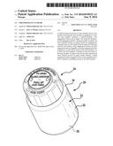
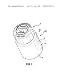
[0019] FIG. 1 is a top oblique view of a child-resistant container.
[0020] FIG. 2 is a first side view of the container of FIG. 1.
[0021] FIG. 3 is a second side view of the container of FIG. 1 viewed orthogonal to FIG. 2.
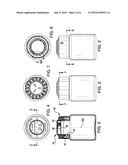
[0022] FIG. 4 is a top view of the container of FIG. 1.
[0023] FIG. 5 is a central vertical sectional view of the container taken along line 5-5 of FIG. 4.
[0024] FIG. 6 is a downward transverse sectional view of a container taken along line 6-6 of FIG. 2.
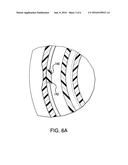
[0025] FIG. 6A is an enlarged view of a portion of the container of FIG. 6.
[0026] FIG. 7 is a downward transverse sectional view of the container taken along line 7-7 of FIG. 3.
[0027] FIG. 8 is a top view of a closure of the container.
[0028] FIG. 9 is a bottom view of the closure.
[0029] FIG. 10 is a bottom oblique view of the closure.
[0030] FIG. 11 is a central vertical sectional view of the closure taken along line 11-11 of FIG. 8.
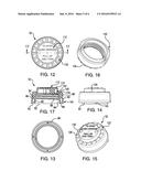
[0031] FIG. 12 is a top view of an inner member of the closure.
[0032] FIG. 13 is a bottom view of the inner member.
[0033] FIG. 14 is a side view of the inner member.
[0034] FIG. 15 is a top oblique view of the inner member.
[0035] FIG. 16 is a bottom oblique view of the inner member.
[0036] FIG. 17 is a central vertical sectional view of the inner member taken along line 17-17 of FIG. 12.
[0037] FIG. 18 is a top view of an outer member of the closure.
[0038] FIG. 19 is a bottom view of the outer member.
[0039] FIG. 20 is a side view of the outer member.
[0040] FIG. 21 is a top oblique view of the outer member.
[0041] FIG. 22 is a bottom oblique view of the outer member.
[0042] FIG. 23 is a central vertical sectional view of the outer member taken along line 23-23 of FIG. 18.
[0043] Like reference numbers and designations in the various drawings indicate like elements.
DETAILED DESCRIPTION
[0044] FIG. 1 shows a container 20 comprising a container body 22 and a closure 24. The exemplary container body is a molded plastic single-piece member (e.g., roto-molded or blow molded or injection molded). The exemplary body has a base 30, a sidewall 32 extending upward from the base, a shoulder 34 extending upward from the sidewall, and a neck 36 (FIG. 5) extending upward from the shoulder and extending to a rim 38 to define a body opening or mouth 40. The neck bears an external thread 42 for engaging an internal thread of the closure. The neck defines a central longitudinal/vertical axis 500.
[0045] The exemplary closure is a two-piece closure comprising an outer piece or member 50 and an inner piece or member 52. An exemplary outer member and inner member are molded plastic (e.g., injection molded). Exemplary plastics are polyolefins such as polypropylenes and polyethylenes. The closure may comprise an additional member such as an elastomeric or paper seal or gasket 48, safety seal, or the like.
[0046] As is discussed further below, the outer member 50 and inner member 52 have two pairs of engagement features cooperating with each other. One pair of engagement features allows the outer member in certain circumstances to transmit rotation about the axis 500 to the inner member in a direction to install the closure (i.e., screw the closure onto the body). The other pair in certain circumstances allows the outer member to transmit an opposite unscrewing/removal rotation to the inner member. This unscrewing condition may require application of sufficient force/pressure or manipulation to qualify as a child-resistant action.
[0047] The exemplary outer member 50 (FIG. 21) comprises a sidewall 54 extending upward from a lower end at a rim 56 to an upper end. At the upper end, a web 58 extends across the sidewall. The sidewall has an outer/outboard or outer diameter (OD) surface 60 and an inner/inboard or inner diameter (ID) surface 62. The web has an upper surface 64 and a lower surface or underside 66 (FIG. 22). The exemplary web has a central aperture 68 defined by an inner perimeter 70 of the web with an outer perimeter of the web being at the sidewall upper end.
[0048] As is discussed further below, the underside 66 of the outer member 50 upper web bears an engagement feature for engaging with a mating engagement feature of the inner member 52 to transmit sufficient torque to screw the closure on in the installation condition but not, in at least some circumstances, transmit sufficient unscrewing torque.
[0049] The inner member 52 (FIG. 17) comprises an inner sidewall 80 extending upward from a lower rim 82 to an upper end and having respective ID 84 and OD 86 surfaces. The ID surface 84 bears the internal thread 88 for engaging the external thread 42 of the neck. An outer sidewall 90 is spaced radially outboard of the inner sidewall 80 and extends upward from a lower rim 92 to an upper end and has ID 94 and OD 96 surfaces. Radial/axial webs 98 (e.g., partial height) may join the inner and outer sidewalls.
[0050] At their upper ends, the inner sidewall 80 and outer sidewall 82 are joined by a web 100 which extends further radially inward and has an underside 102 and an upper surface 104. In this example, a lateral portion of the upper surface bears engagement features complementary to the engagement features of the outer member web. An inner or central portion 110 of the upper web may be exposed through the aperture 68 (FIG. 22) in the outer member web and may bear instructional indicia 112 (FIG. 12). These may be cooperating complementary indicia 114 on the upper surface 64 of the web 58. In the illustrated example, these include written instructions and alignment indicia. In this example, the central portion 110 may protrude into and at least partially through the aperture 68.
[0051] The exemplary installation engagement features 120 (FIG. 22), 122 (FIG. 15) of respective members 50, 52 are shaped and dimensioned so that no force or torque other than the turning torque applied to the outer member is required to screw the closure on to the body. For example, the features 120, 122 may be barbs having first surfaces 124, 126 positioned to engage each other during installation and angled so that the installing torque drives the outer member downward into firmer engagement with the inner member thus requiring the user to provide no downward pressure to install. Opposite surfaces 128, 130 may be angled oppositely so that an uninstalling rotation of the outer member causes the opposite surfaces to cam against each other lifting the outer member up and out of driving engagement with the inner member. Thus, only a very massive downward force applied in the absence of other actuation discussed below would allow the outer member to impart sufficient unscrewing torque to the inner member.
[0052] For unscrewing the closure, the inner member and outer member have cooperating features 140, 142 (FIG. 6A). As exemplary features, the inner member 52 outer sidewall 90 has one or more downward projections 140 (e.g., a pair of diametrically opposite downward projections 140 (FIG. 14)) protruding below a remaining lower rim 92 of the inner member outer sidewall. To cooperate with the projections 140, as exemplary features 142 the outer member 50 sidewall 54 (FIG. 10) has, near its lower rim, a radially inwardly projecting bead 150 having one or more gaps 142 (e.g., a pair of diametrically opposite gaps 142). The aforementioned alignment indicia may indicate when these features 140 and 142 are circumferentially aligned to engage each other.
[0053] Normally, the lower ends 152 (FIG. 11) of the two projections 140 are slightly above the bead 150 so that the outer member can rotate freely in the unscrewing direction relative to the inner member. If the gaps are aligned with the projections, the outer member may be pulled slightly upward with the projections becoming captured in the gaps. Further upward movement is stopped by engagement of the bead with the rim 92 of the inner member outer sidewall.
[0054] With the projections 140 captured in the gaps 142, the inner member may be unscrewed from the bottle by turning the outer member so that rotation of the outer member is transmitted to the inner member via the gaps' capture of the projections.
[0055] The double sidewall of the inner member facilitates one or more advantages relative to a hypothetical single wall variant. First, it gives a softer, more ergonomic feel than a hard stop feel associated with a rigid single sidewall. Nevertheless, single sidewall variants are not precluded.
[0056] One or more embodiments of the present invention have been described. Nevertheless, it will be understood that various modifications may be made without departing from the spirit and scope of the invention. For example, desirability of reusing existing molding and/or capping equipment may influence particular implementations. Accordingly, other embodiments are within the scope of the following claims.
User Contributions:
Comment about this patent or add new information about this topic:
Images included with this patent application:
 |  |
 |  |
 |  |
 |
| Similar patent applications: | |
| Date | Title |
|---|---|
| 2015-12-03 | Child-resistant closure |
| 2016-09-01 | Cover removal system for use in controlled environment enclosures |
| 2017-08-17 | Machine and method for the automatic preparation of substances for intravenous application |
| 2016-06-16 | Tamper resistant package and methods of making same |
| 2016-06-23 | Assembly and system for connecting a closure to a syringe |
| New patent applications in this class: | |
| Date | Title |
|---|---|
| 2017-08-17 | Capping machine |
| 2016-02-04 | Non-removable tamper resistant lid |
| 2016-01-28 | Dispensing apparatus, method of dispensing, capping apparatus and method of capping |
| 2015-11-05 | Device and method for closing filled containers with a screw cap |
| 2012-11-01 | Semi-automated cap securing apparatus |
| New patent applications from these inventors: | |
| Date | Title |
|---|---|
| 2017-06-22 | Bowtie hinges |
| 2017-05-18 | Solid stick applicators and methods |
| 2016-10-13 | Child-resistant closure |
| 2013-04-04 | Container assembly |
| Top Inventors for class "Package making" | |
| Rank | Inventor's name |
|---|---|
| 1 | Donald E. Weder |
| 2 | Dennis J. May |
| 3 | Samuel D. Griggs |
| 4 | Patrick R. Lancaster, Iii |
| 5 | Giuseppe Monti |