Patent application title: COMPUTERISED FEED GROUTING SYSTEM FOR MULTIPLE INLET SLEEVE PIPES
Inventors:
Mauro Del Francese (Roma (rm), IT)
IPC8 Class: AE02D312FI
USPC Class:
405269
Class name: Chemical cementitious (e.g., grouting) injector
Publication date: 2016-05-26
Patent application number: 20160145823
Abstract:
A system for feeding consolidating mixture for multiple inlet sleeve
pipes used for the consolidation grouting of loose ground comprising a
computerised distributor valve having an inlet connection connected to a
grout pumping system and a plurality of outlet connections capable of
delivering cementitious grout to each of the individual inlet pipes of
the multiple inlet sleeve pipe connected hydraulically thereto. Each
outlet connection has a servo-valve, a pressure measuring device and a
flow measuring device connected to a process controller capable of
carrying out any desired feed sequence to each individual pipe present in
the sleeve pipe, monitoring the pressure and volume of mixture injected.Claims:
1. A system for feeding consolidating 1 mixture for multiple inlet sleeve
pipes suitable for the consolidation of loose ground of the type
comprising at least one inlet conduit connected to the grout pumping
system and a plurality of outlet conduits each of which can be connected
to the corresponding inlet conduit of the said sleeve pipe, wherein it
comprises: a main delivery body, preferably comprising a conduit which
extends linearly having at least one inlet connection connected to the
existing grout pumping station and a plurality of outlet connections
intended to feed the corresponding inlets present in the multiple feed
sleeve pipe; each outlet connection has an opening/closing servo-valve
comprising integrated operating means which can be controlled remotely;
each outlet connection has a flow transducer capable of generating
electrical signals proportional to the flow of grout passing through, the
measuring device being mounted either upstream or downstream of the
servo-valve; each outlet connection has a pressure transducer capable of
generating electrical signals proportional to the pressure of the
injected grout measured downstream from the servo-valve; a programmable
controller provided with sufficient memory and a sufficient number of
electrical input and output signals; connection means, preferably but not
necessarily of the electrical type, between the controller and the
servo-valves, and flow and pressure measuring devices; an operating
software program downloaded or downloadable into the controller to allow
any sequence of opening the servo-valves during the grouting stage to be
performed; the controller being capable of implementing any
opening/closing sequence of the servo-valves on the basis of instructions
included in the operating program, keeping the pressure and flow values
of the grout through each outlet connection controlled and/or recorded
respectively.
2. A system for feeding consolidating mixture according to claim 1, wherein the controller operates a sequence for simultaneous feeding all the secondary pipes present in the sleeve pipe connected thereto bringing about simultaneous opening of all the corresponding servo-valves, monitoring pressure and flow respectively for each of these in real time and bringing about the closure of each individual servo-valve when a predetermined delivered pressure and/or flow limit is reached.
3. A system for feeding consolidating mixture according to claim 1, wherein the main delivery body has incorporated mixing means to mix the grout within the main delivery body.
4. A system for feeding consolidating mixture according to claim 3, wherein the said mixing means for mixing the grout within the main delivery body substantially comprises a spiral rotor which extends almost the entire length of the body which is caused to rotate at a suitable rotation speed by suitable incorporated drive means.
5. A system for feeding consolidating mixture according to claim 4, wherein the drive means for the incorporated mixer means comprises an electric motor with or without a mechanical gearbox.
6. A system for feeding consolidating mixture according to claim 1, wherein the distributor body has at least one manually openable outlet so that the interior of the distributor body can be inspected and cleaned.
7. A system for feeding consolidating mixture according to claim 1, wherein incorporated means are present for washing the system located within the main delivery body and preferably comprising nozzles located within the cylindrical cavity present in the distributor body which inject highly pressurised water provided by a suitable external pumping system.
8. A system for feeding consolidating mixture according to claim 1, wherein the mixing system may also have different geometrical forms such as tubular, cylindrical, spherical or hemispherical.
9. A system for feeding consolidating mixture according to claim 1, wherein each outlet connection may have a further servo-valve which allows water to be injected from the attached pumping system and incorporated in each individual pipe to allow them to be washed individually.
10. A system for feeding consolidating mixture for multiple inlet sleeve pipes suitable for the consolidation of loose ground of the type comprising at least one inlet conduit connected to a grout pumping system and a plurality of outlet conduits each of which can be connected to the corresponding inlet conduit of the sleeve pipe, wherein it comprises: a main body having at least one inlet connection capable of being connected to a grout pumping station and a plurality of outlet connections intended to feed corresponding inlets present in the multiple feed sleeve pipe; each outlet connection has a servo-valve whose closing/opening can be operated from a remote position; each outlet connection has a flow transducer mounted upstream or downstream from the servo-valve capable of generating electrical signals proportional to the flow of grout passing through it; each outlet connection has a pressure transducer capable of generating electrical signals proportional to the pressure of the grout injected measured downstream of the servo-valve; a programmable controller or processor capable of receiving input signals from the flow and pressure measuring devices and capable of controlling selective operation of the servo-valves, the controller being programmed to perform a sequence of opening/closing of the servo-valves while keeping the pressure and flow values for the grout passing through each outlet connection controlled and/or recorded respectively.
11. A process for feeding consolidating mixture to multiple inlet sleeve pipes suitable for consolidating loose ground through a feed system according to claim 1, comprising the stages of keeping the pressure and flow values of the grout passing through each outlet connection controlled and/or recorded respectively and controlling selective operation of the servo-valves in an open/closing sequence.
12. A process according to claim 11, in which closure of each individual servo-valve is brought about when a predetermined delivered pressure and/or flow limit is reached.
13. A process according to claim 11, in which the opening/closing sequence of the servo-valves comprises a sequence of simultaneous feeding to all the secondary pipes present in the sleeve pipe connected thereto, controlling simultaneous opening of all the corresponding servo-valves monitoring flow and pressure respectively for each of these in real time and closing each individual servo-valve when a predetermined delivered pressure and/or flow limit is reached.
Description:
[0001] This invention relates in general to the sector of the
consolidation of loose unconsolidated ground, more particularly a
computerised system for the controlled feed of consolidating fluids of
various kinds injected into sleeve pipes inserted in the ground needing
to be consolidated.
[0002] Over the years the excavation of tunnels has resulted in appreciable changes which have mainly been made possible through the use of modern equipment and new materials which overall have made it possible to carry out major civil engineering works that were impossible in the past. One of the areas in which research effort has been concentrated is undoubtedly that relating to making excavations in poorly cohesive ground where there is a danger of slumping, both before and after the work has been carried out, safely and quickly.
[0003] The known technique for the consolidation of loose ground, often known as unconsolidated ground, is that of using so-called sleeve pipes, which are substantially very long pipes inserted into holes made in the ground, used so that suitable consolidating fluids can be injected under pressure to penetrate the ground, significantly increasing its cohesion. Sleeve pipes are distributed according to geometries determined at the design stage which typically provide distances between adjacent holes that vary between one and two metres. The density of sleeve pipes per unit surface area of ground requiring consolidation is therefore rather high, as are consequently the corresponding costs of materials and labour required for carrying out such consolidation work.
[0004] The sleeve pipes normally used substantially consist of a tubular conduit, which may comprise various sections which can be joined together, the typical length of which may vary from a few metres to a few tens of metres. Along the axial length of such a tubular conduit a number of radial holes made in regular succession are covered by a resilient sleeve which functions as a non-return valve, known in the jargon as a "valve". The pipes are used by running them through holes of suitable depth and diameter greater than the maximum radial dimensions of the sleeve pipe made in the ground needing consolidation.
[0005] Consolidation comes about substantially through injecting a suitable consolidating mixture under pressure into these pipes which on leaving the said valves penetrates the portions of ground adjacent to them, substantially increasing cohesion. Before beginning injection proper the annular cavity between the sleeve pipe and the inner wall of the hole in the ground is filled with a known special cementitious mixture forming a kind of sheath, which has the function of preventing the mixture subsequently injected leaving the valves at various depths radially and consequentially through the double or single packer closing off each valve from the ground, from rising to the surface instead of substantially penetrating the ground in a radial direction. Given its deliberately poor mechanical strength characteristics due to its composition, a sheath of this kind is easily locally fractured in the vicinity of each valve through the effect of the injection pressure proper, as a result of which the cementitious consolidation mixture can penetrate radially into the unconsolidated ground needing treatment.
[0006] In the sleeve pipes currently used in industry consolidating injection of the specialised cementitious grout takes place through the use of a moving plug known as a packer which is inserted into the sleeve pipe until it reaches a particular depth and thus acts as a selective element in such a way that injection only occurs through a predetermined length of the pipe, using individual sections of the pipe from time to time and thus in fact selectively feeding one or a small number of valves present in that length of pipe, hereinafter referred to as a "zone". The plugging packer has in fact the function of isolating a length of pipe by means of an upper seal and a lower seal. The centre of the packer is fed by an external pumping system through a suitable feed conduit, and therefore when the packer reaches the desired depth within the body of the sleeve pipe the pressurised cementitious mixture can exit via the valve(s) present in the length between the upper and lower seals and in fact make it possible to inject from the preselected zone of the pipe. The use of sleeve pipes according to the known art is quite complex and costly, above all during the stage of consolidation grouting which requires multiple repositioning of the packer plug so that the requisite valves within the sleeve pipe can be selectively fed.
[0007] Patent application BO2013A000070 (corresponding to PCT/IB2014/059088) describes an innovative multiple feed sleeve pipe in which each zone comprising one or a small number of valves is individually fed by its own feed conduit avoiding the need for use of the packer plug and therefore introducing an appreciable simplification into the grouting procedure.
[0008] This innovative sleeve pipe substantially has a multiple feed, in particular a main central conduit through which the first cementitious mortar filling the gap between the sleeve pipe and the inner surface of the hole in the ground (sheath) can be injected and a plurality of secondary pipes each connected to a different zone of the sleeve pipe, typically one or a small number of valves. Reference is made to the abovementioned patent application for a detailed description of a conventional sleeve pipe, the sleeve pipe with a multiple feed and the substantial differences between them.
[0009] In addition to the innovative multiple feed sleeve pipe that application also describes the requisite drum distribution valve used to serve it. This distributor is connected to a pumping system and through a drum selector makes it possible to provide a selective feed to the individual secondary feed pipes to the valves and the main pipe for the sheath.
[0010] Tests carried out on site have revealed that the new multiple feed sleeve pipe provides excellent performance and use of the drum distribution valve is functional and avoids the practice of inserting the packer, appreciably reducing grouting times.
[0011] It is important to point out that the portion of ground grouted by each individual valve has a penetration/impregnation resistance which typically increases as injection proceeds, in particular with the volume of mixture injected and penetrating the ground. In practice radial penetration into the ground through the so-called valve takes place when the initial value of the minimum resistance pressure of the adjacent ground is reached upstream (said to be the initial threshold corresponding to opening of the valve) and then continues gradually, requiring an increase in the pumping pressure needed to continue impregnation, as a result of which, if all the secondary pipes are fed simultaneously, the volume of mixture injected initially runs preferably through the valves having a low opening pressure threshold, which are those surrounded by the very porous ground, but when the resistant pressure in those zones increases through the saturation effect other valves surrounded by less porous ground begin to open and deliver because the pressure reaches and exceeds their corresponding minimum opening threshold value.
[0012] This "natural" grouting sequence, which is considered to be the optimum, cannot however be implemented using existing sleeve pipes, including multiple feed sleeve pipes when fed by a drum distributor valve as described in the abovementioned patent application.
[0013] The main object of this invention is to provide an innovative distributor valve with associated injection equipment which replaces the drum distributor as a system for feeding the innovative multiple feed pipe, considerably hastening the grouting process.
[0014] Another object of this invention is that of providing a distributor valve capable of performing a grouting sequence strategically based on grouting into the most unconsolidated and progressively less unconsolidated portions of ground until all the zones present in the sleeve pipe have been fed, in other words capable of controlling the grouting process through simultaneous feeding of all the individual secondary pipes. Another object of this invention is that of providing a distributor valve which for each injected zone is capable of controlling the volume of consolidating mixture injected and an injection pressure controlled by an electronic system which automatically controls the various stages, producing documentation suitable for certification and testing of each sleeve pipe installed and the precise quantities by volume and pressure of the mixture delivered from the one or several valves connected to each individual circuit in the new sleeve pipe.
[0015] Yet another object is that of providing an automatic and intelligent system which as an alternative to a drum distribution valve is capable of simultaneously feeding all the secondary inputs to the sleeve pipe making it possible to achieve a grouting sequence dictated by the actual composition of the ground in the various zones while at the same time not losing the possibility of monitoring and measuring the pressure and volume of consolidating mixture delivered from each individual zone in the sleeve pipe. The system also provides for automatic washing with water, incorporating the requirement of being able to resume consolidation grouting of the ground after a period of time.
[0016] The abovementioned objects are accomplished through a grouting system described in the appended claims.
[0017] According to one aspect of the invention, the system for feeding consolidating mixture is applied to multiple inlet sleeve pipes suitable for the consolidation of loose ground of the type comprising at least one inlet conduit connected to the grout pumping system and a plurality of outlet conduits which can each be connected to the corresponding inlet conduit in the sleeve pipe.
[0018] The system further comprises:
[0019] a main body having at least one inlet connection capable of being connected to a grout pumping station and a plurality of outlet connections intended to feed corresponding inlets present in the multiple feed sleeve pipe;
[0020] each outlet connection has a servo-valve whose closing/opening can be activated from a remote position;
[0021] each outlet sleeve has a flow transducer mounted upstream or downstream from the servo-valve capable of generating electrical signals proportional to the flow of grout passing through it, the measuring device being each outlet sleeve has a pressure transducer capable of generating electrical signals proportional to the pressure of the grout injected measured downstream from the servo-valve;
[0022] a programmable controller or processor capable of receiving input signals from the flow and pressure measuring devices and capable of controlling selective operation of the servo-valves, the controller being programmed to perform a sequence of opening/closing of the servo-valves while keeping the pressure and flow values respectively of the grout passing through each outlet connection controlled or recorded respectively.
[0023] More particularly, the feed system comprises:
[0024] a main delivery body, preferably comprising a conduit which extends linearly having at least one inlet connection connected to the existing grout pumping station and a plurality of outlet connections intended to feed the corresponding inlets present in the multiple feed sleeve pipe;
[0025] each outlet connection has an opening/closing servo-valve comprising integrated operating means which can be controlled remotely;
[0026] each outlet connection has a flow transducer capable of generating electrical signals proportional to the flow of grout passing through, the measuring device being mounted either upstream or downstream of the servo-valve;
[0027] each outlet connection has a pressure transducer capable of generating electrical signals proportional to the pressure of the injected grout measured downstream from the servo-valve;
[0028] a programmable controller provided with sufficient memory and a sufficient number of electrical input and output signals;
[0029] connection means, preferably but not necessarily of the electrical type, between the controller and the servo-valves, and flow and pressure measuring devices;
[0030] an operating software program downloaded or downloadable into the controller to allow any sequence of opening the servo-valves during the grouting stage to be performed; the controller being capable of implementing any opening/closing sequence of the servo-valves on the basis of instructions included in the operating program keeping the pressure and flow values of the grout through each outlet connection controlled and/or recorded respectively.
[0031] In this consolidating mixture feed system the controller can operate a simultaneous feed sequence for all the secondary pipes present in the sleeve pipe connected to it controlling simultaneous opening of all the corresponding servo-valves, monitoring pressure and flow respectively for each of these in real time and closing each individual servo-valve when a predetermined delivered pressure and/or flow limit is reached.
[0032] In accordance with a particular aspect, the main delivery body has incorporated mixing means to mix the grout within the said main delivery body.
[0033] According to another particular aspect, the mixing means for mixing the grout within the main delivery body substantially comprises a spiral rotor extending over almost the entire length of the body which is caused to rotate at a suitable rotation speed by suitable incorporated drive means.
[0034] According to another particular aspect the drive means for the incorporated mixing means comprises an electric motor with or without a mechanical gearbox.
[0035] According to a further particular aspect the distributor body has at least one manual opening outlet so that the interior of the distributor body can be inspected and cleaned.
[0036] According to a further particular aspect the system has incorporated means for washing the system located within the main delivery body and preferably comprising nozzles located within the cylindrical cavity present in that distributor body which inject highly pressurised water supplied by a suitable external pumping system.
[0037] According to another particular aspect the mixing system may also have different geometrical shapes such as tubular, cylindrical, spherical or hemispherical.
[0038] According to another particular aspect each outlet connection may have a further servo-valve which allows water to enter from the attached pumping system incorporated in each individual conduit to allow them to be washed individually.
[0039] The invention also relates to a process for feeding consolidating mixture in multiple inlet sleeve pipes designed for the consolidation of loose ground through a feed system of the type indicated above comprising the stages of keeping the grout pressure and flow values passing through each outlet connection controlled and/or recorded respectively, and controlling selective operation of the servo-valves in an opening/closing sequence.
[0040] According to another aspect the process is such that each individual servo-valve is closed when a predetermined delivery pressure and/or flow limit is reached.
[0041] According to a further aspect, the process is such that the opening/closing sequence of the servo-valves comprises a sequence of simultaneously feeding all the secondary pipes present in the sleeve pipe connected thereto, controlling simultaneous opening of all the corresponding servo-valves monitoring pressure and flow respectively in each of these in real time and closing each individual servo-valve when a predetermined delivered pressure and/or flow limit is reached.
[0042] This invention will now be better described with the help of the appended figures in which:
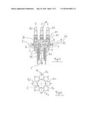
[0043] FIG. 1 is a partial longitudinal cross-section of the distribution head of the multiple feed sleeve pipe according to the teaching of patent application BO2013A000070;
[0044] FIG. 2 is a transverse cross-section of the pipe bundle of the pipe in FIG. 1 along the line Z-Z in FIG. 6, according to the teaching of patent application BO2013A000070;
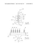
[0045] FIGS. 3A and 3B show respectively a diagrammatical side view of the sleeve pipe according to this invention and a magnified view of one of its typical outlet connections;
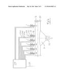
[0046] FIG. 4 diagrammatically illustrates the computerised feed system according to this invention;
[0047] FIG. 5 shows a variant construction of the valve delivery main in FIG. 3A;
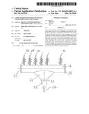
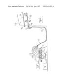
[0048] FIG. 6 shows the operating diagram for this invention on site.
[0049] FIG. 1 diagrammatically illustrates a cross-section of the distribution head of the multiple inlet pipe according to the teaching of patent application BO2013A000070 which the distribution system according to this invention is intended to feed.
[0050] The head of such a pipe comprises two separate bodies. In particular a distribution body 1 which is permanently of one piece with the pipe and a distribution head 4 temporarily connected thereto by means of tapered sealed collar ring 12 tightened by screws 13. Distribution body 1 has a central hole 6 and a plurality of peripheral holes such as hole 5 and hole 7 which are angularly equidistant from each other. As will be better described below, but also as disclosed in patent application BO2013A000070, to which reference is made for all further details, central pipe 6 feeds central conduit C in FIG. 2 which extends as far as the opposite extremity of the pipe and is intended for primary injection of the mortar sealing the sheath, while the various peripheral holes 5, 7, etc., respectively feed the various sleeve pipes R1, R2, R3, Ri which are arranged around central pipe C to form a pipe bundle as illustrated in FIG. 2 intended for the secondary injection of consolidating mixtures for the proper consolidation of ground. Holes 5, 6, 7 present in distributor body 1 communicate with appropriate cavities 2 and 3 formed respectively so as to receive and permanently retain pipes C, R1-Ri by adhesive bonding or mechanical attachment. Distribution body 1 without collar 12 remains permanently attached to the sleeve pipe and in fact remains an integral part thereof having the function of offering removable distributor 4 an interface for attachment and a fluid seal during grouting.
[0051] Distributor body 4 is instead connected to the distribution system and can be disconnected and reconnected to the next pipe which has to be injected. Typically it has a substantially cylindrical body which receives extra feed pipes AC, A1-Ai and has corresponding conduits 10, 8-9 connected thereto in a position of axial coincidence with corresponding pipes 6, 5-7 present in the body of distributor 1.
[0052] In FIG. 2 it will be seen that each pipe R1-Ri comprising the outer pipe bundle has at least one valve 14 for the exit of the cementitious consolidating grout in radial direction 15.
[0053] FIG. 3A diagrammatically illustrates the main distributor body forming part of this invention comprising a principal body 16 of substantially but not specifically cylindrical shape having an inlet connection 32 and a plurality of outlet connections 28, 29, 30 in a number N equal to or greater than that of pipes Ac, A1-Ai in FIG. 1. Connection 32 communicates with cylindrical body 16 and is connected with the pipe 33 originating from a cementitious grout pumping system, which is not shown. Body 16 has covers 35 so that the interior of body 16 can be inspected and/or cleaned.
[0054] FIG. 3B diagrammatically illustrates an enlargement of each outlet connection, in particular showing how each connection 17 has a servo-valve 18 together with an actuator 23 for remotely opening and closing the flow, a pressure transducer 19 capable of measuring the pressure of the fluid downstream from the servo-valve, converting it for example into an electrical signal, and a flow transducer 20 capable of measuring the flow of fluid passing through and converting it into a signal, for example an electrical signal. Preferably, but not necessarily, transducers 18 and 19 have a visual indicator 21 and 22 so that the pressure and flow of the fluid passing downstream from the servo-valve can be read off. Servo-valve 18 and transducers 18 and 19 have an electrical connection 24 which may also be of an alternative nature such as pneumatic, hydraulic or other nature, comprising means for connection to designated remote control means.
[0055] During operation of the system the flow of cementitious grout follows the route indicated by arrows 34, 26 and 27.
[0056] FIG. 4 shows a diagram of the automatic computerised distribution system according to this invention which substantially comprises a body of elongated cylindrical shape 16 having an inlet connection 31 and a plurality N of outlet connections 28, 29, 30, etc., each respectively provided with a servo-valve 18, including suitable actuator means to be able to open, close or partly reduce the flow of fluid passing through, a pressure transducer 19 and a flow transducer 20.
[0057] To inlet connection 31 there is connected a pipe connected to a suitable consolidating mixture pumping system, not shown, while each outlet connection N is connected to a pipe 25 connected to the corresponding single feed inlet present in the feed head of the multiple inlet sleeve pipe shown in FIG. 1.
[0058] The system provides for a process controller CP comprising a computer having sufficient memory and a suitable number of input and output signals. All servo-valves 18 are connected to controller CP through control cables 24A and all transducers 19 and 20 through signal connections 24B and 24C. A connection 36 intended to communicate with the pumping unit to control its function automatically may optionally be connected to process controller CP.
[0059] Through connections 24A process controller CP is capable of controlling the total and/or partial opening and closing of each of servo-valves 18 and therefore making it possible to deliver pressurised cementitious grout taken from distributor body 16 to each outlet pipe 25 in any operating sequence dictated by the software operating program loaded into process controller CP.
[0060] In the course of delivery the pressure and flow of the consolidating fluid passing through each individual outlet connection is recorded as a result of signals provided by transducers 19 and 20 transmitted to process controller CP through connections 24B and 24C.
[0061] Among possible injection sequences the system also makes it possible to control the so-called simultaneous opening of all servo-valves 18, while at the same time keeping the pressure and volume respectively of the grout passing through each individual connection strictly measured and making it possible to achieve an injection cycle which is considered to be the optimum in that the flow of cementitious grout injected follows a sequence which depends on the different penetration resistance of the various portions of ground along the length of the sleeve pipe, as mentioned previously.
[0062] In the course of this simultaneous feed, the grout pumped from the pumping system into delivery main 16, finding all the servo-valves open, begins to increase the pressure until it reaches the minimum opening pressure threshold originating from the valve or valves serving highly porous ground and therefore offering a low initial threshold pressure value for starting penetration, unlike more compact portions of ground which instead have a higher minimum pressure threshold for initiating the grouting procedure. When the flow of grout begins to impregnate this portion or portions, the ground reacts, offering a back pressure which usually gradually increases with the volume injected, and therefore the pressure within main 16 and consequently the pressure at all the valves in the sleeve pipe increases.
[0063] This increase in pressure proceeding inexorably as a result of injection then also reaches the opening threshold value for the portions of more compact ground until all open and allow grout to flow through, the flow transducer making it possible to verify that this has actually occurred.
[0064] It is pointed out that if there were to be cavities of unexpected size in some portions of ground the increase in pressure could slow, but once a maximum injected volume had been reached the controller would shut off the servo-valve in question allowing the pressure to resume its upward path, recording and providing evidence about which valve had been switched off because the injection volume alone had been reached, when printing out the final report. Control system CP stores this data and automatically washes the individual pipe allowing grouting to be resumed through a deliberate choice and automatically in order if appropriate to reinject the consolidating fluid a second time on a later occasion.
[0065] This simultaneous cycle, which is considered to be the optimum, cannot be performed by any of the existing systems currently available and represents one of the most important characteristics of this invention, and is also an appreciable advantage.
[0066] Another advantage lies in the possibility of process controller CP recording time, pressure, flow and volume of consolidating fluid injected in real time for each servo-valve (and therefore for each portion of ground treated), producing a certificate for the actual process with a certainty which has hitherto been wholly unknown.
[0067] FIG. 5 diagrammatically illustrates an alternative way of operating the system in FIG. 4 in which distributor body 16 substantially has a mixer incorporated within the cylindrical body of distributor whose function is to keep the cementitious grout delivered to the sleeve pipes well mixed and free of clumps. Spiral rotor 38 of the mixer connected to shaft which is substantially located along the central axis of the inner cylindrical cavity of distributor body 16, gearbox 39 and electric motor 40 comprising the drive unit, which may also be of the hydraulic, pneumatic or other type, will be seen in the figure. The mixer unit is also preferably controlled by process controller CP; the description of the distribution in this phase is merely representative, it may also be performed in other ways or with other dimensions while complying with the functional process.
[0068] FIG. 6 shows an operating diagram of the computerised distribution system in question on site where CP is the process controller, P is a pumping unit, 16 is the distributor body, in this case being understood to comprise a suitable number N of outlet connections described in FIG. 3B, 24 are the electrical connections between CP and the N outlet connections, 33 is the pipe connecting pumping system P to distributor main 16 through a connecting funnel 31 while 42 and 43 are multiple inlet sleeve pipes like that in the case in point. FIG. 6 illustrated here shows the presence of control centre CP and pumping unit P located close to distribution main 16, but this configuration is only diagrammatical, therefore both control centre CP and pumping system P may also be located even an appreciable distance from distribution main 16 without compromising perfect operation. Again in FIG. 6, 44 indicates the excavation front which is being consolidated, 49 diagrammatically illustrates one of the many "valves" present in pipes 42 and 43, while T1 and T2 represent the heads of pipes 2, 41 is the pipe bundle comprising the connecting pipes between the outlet connections from distributor body 16 and feed head pipes T2 of sleeve pipe 42 while in operation.
[0069] The flow of cementitious malt is indicated by directional arrows 45, 46, 47 and 48 respectively.
[0070] From what has been described above it will be seen that this invention accomplishes the objects proposed by providing an automatic feed system for multiple inlet sleeve pipes which proves to be simple, functional, flexible and extremely quick to use. The system operates automatically on the basis of a sequence which is programmable at will, including the optimum process with simultaneous opening of all the servo-valves as described previously.
[0071] Of course the solutions described are provided purely by way of example and therefore without restriction, so that all possible modifications within the scope of a person skilled in the art may be made without going beyond the scope of protection of the invention as defined above and claimed below.
User Contributions:
Comment about this patent or add new information about this topic:
Images included with this patent application:
 |  |
 |  |
 |  |
| Similar patent applications: | |
| Date | Title |
|---|---|
| 2016-02-25 | Subsea device for sediment removal |
| 2016-03-17 | Method for producing steel profiles |
| 2015-02-26 | P squared system (pss) |
| 2016-03-03 | Subsea system delivery to seabed |
| 2016-05-26 | Enhanced ram-style riser tensioner cylinder |
| New patent applications in this class: | |
| Date | Title |
|---|---|
| 2016-06-16 | Method for waterproofing underground structures |
| 2015-12-17 | Device, equipment and method for treating ground, constructions and the like by grouting |
| 2013-01-10 | Device and method for surveying jet grouting piles in the ground |
| 2012-02-16 | Arrangement for a down-the-hole hammer drill for use in soil consolidation through jet grouting |
| 2011-12-22 | Jet grouting equipment |
| Top Inventors for class "Hydraulic and earth engineering" | |
| Rank | Inventor's name |
|---|---|
| 1 | Joop Roodenburg |
| 2 | Thomas P. Taylor |
| 3 | Michael Tjader |
| 4 | Keith K. Millheim |
| 5 | John G. Oldsen |