Patent application title: GOOSENECK SPRAY ASSEMBLY
Inventors:
Matthew David Mccutcheon (Fort Myers, FL, US)
IPC8 Class: AB65D8328FI
USPC Class:
222394
Class name: Dispensing with discharge assistant (e.g., impeller, pump, conveyer, movable trap chamber, etc.) fluid pressure
Publication date: 2016-05-26
Patent application number: 20160145033
Abstract:
A gooseneck spray assembly includes a spray cap and a spray extension. A
spray cap includes an inner channel terminating at an input aperture and
an output aperture. A spray extension includes a hollowed flexible tube
having first and second ends, an elastic coil spring disposed around the
tube, and a length of wire helixically wound around the coil spring. The
first end is engaged within the output aperture to form an air-tight
seal, and the input aperture and the second end define an impermeable
channel.Claims:
1. A gooseneck spray assembly, comprising: a spray cap formed of an
impermeable material defining an inner channel terminating at an input
aperture and an output aperture; and a spray extension engaged with the
output aperture, said extension comprising, a hollowed tube, formed of a
flexible material, and having first and second ends and a tube length
defining a tube axis parallel to the tube length, a coil spring, formed
of an elastic material, disposed around the tube, and having a plurality
of coils and a spring length less than the tube length, the spring length
defining a spring axis along the spring length, and a length of wire
helixically wound around the coil spring, such that along its length, the
wire abuts two adjacent coils; wherein the tube and spring axes are
parallel, the first end is engaged with the output aperture to form an
air-tight seal, and the input aperture and the second end define an
impermeable channel therebetween.
2. The assembly of claim 1, wherein said gooseneck spray extension is frictionally engaged with the output aperture.
3. The assembly of claim 1, wherein the first end is integral with the output aperture.
4. The assembly of claim 1, wherein said spray cap includes an extended portion having an extended portion outside diameter, and the extended portion includes the input aperture and a segment of the inner channel.
5. The assembly of claim 4, wherein said gooseneck spray extension is frictionally engaged with the output aperture.
6. The assembly of claim 4, wherein the first end is integral with the output aperture.
7. The assembly of claim 4, wherein the extended portion includes a first tiered portion having a first tiered outside diameter, and a second tiered portion having a second tiered outside diameter greater than the first outside diameter.
8. The assembly of claim 7, wherein said gooseneck spray extension is frictionally engaged with the output aperture.
9. The assembly of claim 7, wherein the first end is integral with the output aperture.
10. The assembly of claim 1, wherein the input aperture is defined by a section of said spray cap, and the section includes a first section portion having a first section inside diameter and a second section portion having a second section inside diameter greater than the first section inside diameter.
11. The assembly of claim 10, wherein said gooseneck spray extension is frictionally engaged with the output aperture.
12. The assembly of claim 10, wherein the first end is integral with the output aperture.
Description:
FIELD OF THE INVENTION
[0001] The present invention relates to pressurized containers with spray assemblies, and gooseneck structures.
BACKGROUND OF THE INVENTION
[0002] Pressurized containers have been utilized for the delivery of liquid material and gases, and have included a pressurized container and a spray cap. Pressurized containers can include a male or female valve for delivery of a material under pressure. Such valves are respectively engaged with a female or male spray cap, which include a female or male input aperture and output aperture. Elastomeric hollowed tubes have been attached to output apertures of spray caps to assist in focusing the location of where the material is delivered. Such elastomeric tubes have required the maintenance of deformation forces on such tubes to maintain desired deformations.
[0003] A gooseneck electrical structure has included wire-wrapped coil springs surrounding electrical wiring that carries electricity from a power source to a power destination. The wire wrapped coil spring provides a bendable structure that retains its bent shape for a desired positioning of the structure and/or power destination, which has been an electrical light fixture.
SUMMARY OF THE INVENTION
[0004] It is an object of the present invention to provide a gooseneck spray assembly that improves the selectively located application of a material.
[0005] It is another object of the present invention to provide a gooseneck spray assembly that obviates the need to maintain deformation forces on a spray extension to maintain a desired deformation.
[0006] In an exemplary embodiment of the present invention, a gooseneck spray assembly can include a spray cap and a spray extension.
[0007] In an exemplary aspect of the present invention, a spray cap can be formed of an impermeable material that defines an inner channel terminating at an input aperture and an output aperture.
[0008] In another exemplary aspect of the present invention, a spray extension can include a hollowed flexible tube, an elastic coil sprint, and a length of wire. Such a flexible tube can have first and second ends, and a tube length that defines a tube axis parallel to the tube length. Such an elastic coil can be disposed around the tube, and can have a plurality of coils and a spring length that is less than the tube length, with the spring length defining a spring axis along the spring length. Such a length of wire can be helixically wound around the coil spring, such that along its length, the wire abuts two adjacent coils.
[0009] In a further exemplary aspect of the present invention, upon such configuration, the tube and spring axes are coaxial, the first end can be engaged with the output aperture to form an air-tight seal, and the input aperture and the second end define an impermeable channel.
[0010] In a second exemplary embodiment, a spray cap includes an extended portion having an extended portion outside diameter, and the extended portion includes the input aperture and a segment of the inner channel.
[0011] In a third exemplary embodiment building upon the second exemplary embodiment, the extended portion can include a first tiered portion having a first tiered outside diameter, and a second tiered portion having a second tiered outside diameter greater than the first outside diameter.
[0012] In a fourth exemplary embodiment, the input aperture can be defined by a section of the spray cap, with the section including a first section portion having a first section inside diameter and a second section portion having a second section inside diameter greater than the first section inside diameter.
[0013] In yet a further exemplary aspect, a spray extension can be frictionally engaged with an output aperture, or can be integral therewith, which includes molding, adhering, or any other permanent form of engagement.
BRIEF DESCRIPTION OF THE DRAWINGS
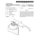
[0014] FIG. 1 illustrates an exemplary gooseneck spray assembly having a spray cap engaged with a container and a gooseneck spray extension.
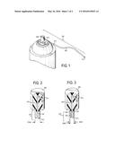
[0015] FIG. 2 illustrates an exemplary spray cap having an extended portion configured to engage a female valve of a container.
[0016] FIG. 3 illustrates another exemplary spray cap in which an extended portion can include a first tiered portion having a first tiered outside diameter, and a second tiered portion having a second tiered outside diameter greater than the first outside diameter.
[0017] FIG. 4 illustrates another exemplary spray cap in which an input aperture can be complementarily sized to engage a female valve of a container.
[0018] FIG. 5 illustrates an exemplary spray cap that includes a first section portion having a first section inside diameter, and a second section portion having a second section inside diameter greater than the first section inside diameter.
[0019] FIG. 6 illustrates an exemplary spray extension having a hollowed tube, a coil spring, and a length of wire.
DETAILED DESCRIPTION
[0020] It is an object of the present invention to provide a gooseneck spray assembly having a plurality of embodiments, which are described, and are to be broadly interpreted, via the disclosure herein.
[0021] It should be noted that this disclosure includes a plurality of embodiments each having a plurality of elements and/or aspects, and such elements and/or aspects need not necessarily be interpreted as being conjunctively required by one or more embodiments of the present invention. In particular, all combinations of elements and/or aspects can enable a separate embodiment of a patentable invention, which may be claimed with particularity in this or any future filed patent applications. Moreover, such elements and/or aspects disclosed herein, whether expressly or implicitly, are to be construed strictly as illustrative and enabling, and not necessarily limiting.
[0022] Further, to the extent the same element and/or aspect is defined differently anywhere within this disclosure, whether expressly or implicitly, the broader definition is to take absolute precedence, with the distinctions encompassed by the narrower definition to be strictly construed as optional.
[0023] Illustratively, perceived benefits of the present invention can include functional utility, whether expressly or implicitly stated herein, or apparent herefrom. However, it is expressly set forth that these benefits are not intended as exclusive. Therefore, any explicit, implicit, or apparent benefit from the disclosure herein is expressly deemed as applicable to the present invention.
[0024] The environment of the present invention includes a pressurized container containing a material under pressure and intended for a sprayed application. Such containers, such as aerosol and pump containers, include a male or female valve with which a respective female or male spray cap is engaged.
[0025] FIG. 1 illustrates an exemplary embodiment of the present invention, in which a gooseneck spray assembly 100 includes a spray cap 200 and a spray extension 300. As further illustrated, spray cap 200 includes an input aperture 212 (see FIG. 2) and an output aperture 214, and spray extension 300 includes first and second ends 312, 314. First end 312 can sealably engage output aperture 214 to define an impermeable channel therebetween.
[0026] FIGS. 2-5 illustrate exemplary embodiments of spray cap 200. Common aspects among embodiments of spray cap 200 include an inner channel 210 for carrying a material from an input aperture 212 to an output aperture 214.
[0027] FIGS. 2 and 3 illustrate exemplary male spray caps 200 that include an extended portion 216 having an outside diameter 216d. As further illustrated, extended portion 216 includes a segment 218 of inner channel 210, and input aperture 212. In an exemplary aspect of the present invention, extended portion 216 can be configured to engage a female valve (not shown) of a container via a particularly sized outside diameter 216d that can friction-fit a female valve having a complementarily sized aperture to create a sealed engagement therebetween. Notably, such engagement can be effectuated via alternative means, such as via an adhesive or molding. Accordingly, material provided from such a valve can be received by input aperture 212 and carried by inner channel 210 to output aperture 214. As illustratively shown in FIG. 2, extended portion 216 can be provided with a uniform diameter 216d.
[0028] FIG. 3 illustrates an alternative exemplary embodiment of a male spray cap 200, in which extended portion 216 can optionally be provided with a plurality of diameters to broaden compatibility of the spray cap. In particular, as illustrated, extended portion 216 can include a first tiered portion 220 having a first tiered outside diameter 220d, and a second tiered portion 222 having a second tiered outside diameter 222d greater than the first outside diameter. Accordingly, extended portion 216 can be configured to engage two differently sized female valves, one for which first tiered outside diameter 220d is sized to frictionally engage, and another for which second tiered outside diameter 222d is sized to frictionally engage.
[0029] FIGS. 4 and 5 illustrate exemplary female spray caps 200 according to the present invention. As illustratively shown, like male versions, female spray caps 200 also include an inner channel 210 for carrying a material from an input aperture 212 to an output aperture 214. Accordingly, a male valve (not shown) of a container can engage input aperture 212 to accommodate the provisioning of a material from a container (not shown) to the input aperture. Accordingly, input aperture 212 can be complementarily sized to engage a particularly sized male valve.
[0030] FIG. 5 illustrates an alternative exemplary embodiment of a female spray cap 200, in which input aperture 212 can be defined by a section 224 of the spray cap that includes a first section portion 226 having a first section inside diameter 226d, and a second section portion 228 having a second section inside diameter 228d greater than the first section inside diameter. Accordingly, input aperture 212 can be configured to engage two differently sized male valves, one for which first section inside diameter 226d is sized to frictionally engage, and another for which second section inside diameter 228d is sized to frictionally engage.
[0031] FIG. 6 illustrates an exemplary spray extension 300 that can be engaged with output aperture 214 to extend the point at which a material can be provided. As illustrated, spray extension 300 can include a hollowed tube 310, a coil spring 320, and a length of wire 330.
[0032] In an exemplary aspect of the present invention, hollowed tube 310 can include first and second ends 312, 314 and a tube length TL that defines a tube axis TA that is parallel to the tube length. Notably, tube 310 can formed from any one or more materials that provide sufficient flexibility to be functionally compatible with the present invention, such as, for example and not in limitation, a plastic or rubber.
[0033] In another exemplary aspect of the present invention, coil spring 320 can include a plurality of coils 322, and can be disposed around tube 310. Further, coil spring 320 can include a spring length SL that can be less than tube length TL, and also, can define a spring axis SA along the spring length. In an exemplary aspect, spring length SL can be less than tube length TL so as not to cover first end 312, which can impede its engagement with output aperture 214. According to the present invention, coil spring 302 can be formed from any one or more materials that provide an elastic property, such as, for example and not in limitation, a metal, plastic, or rubber.
[0034] In a further exemplary aspect of the present invention, wire 330 can be helixically wound around or along coil spring 320, such that along its length, the wire abuts two adjacent coils 322. Wire 330 can be formed of any one or more materials, such as a metal, plastic, or rubber, for example and not in limitation, that are functionally compatible with the present invention as described. Accordingly, coil spring 320 and length of wire 330 in combination provide a gooseneck function, which allows spray extension 300 to be manually angled in various desired orientations and to at least substantially retain each orientation until subsequently modified.
[0035] As further illustrated in FIG. 6, when spray extension 300 is so configured, tube axis TA and spring axis SA are in parallel. Further, first end 312 can be engaged with output aperture 214 to form an air-tight seal, such that input aperture 212 and second end 314 define an impermeable channel therebetween. According to the present invention, engagement of first end 312 and output aperture 214 can be effectuated via frictional engagement, with either friction fitting within the other. Alternatively, such engagement can be effectuated via utilization of an adhesive or via molding.
[0036] Notably, in any embodiment of the present invention, the various elements and/or aspects can be provided in any desired shape and/or size that are functionally compatible with the present invention as described and/or claimed, and as expressly stated, are not limited to any particular shape or size illustratively described herein or apparent herefrom. Accordingly, exemplary shapes and/or sizes can include any shape or size having one or more geometric shapes, whether having symmetric or asymmetric portions, and without shape or size limitations relative to other elements unless necessary to the functionality of the present invention. For example, elements of the present invention can be provided with cylindrical and/or round aspects. However, it should be noted that non-round aspects can be utilized insofar as related aspects are complementarily shaped.
[0037] Further, it is expressly set forth that any structural element and/or aspect described herein can be formed from any one or more desired materials that provide functional compatibility with the respective component and/or aspect related thereto. Thus, any one or more of a plastic, rubber, metal, alloy, wood, elastomer, crystalline material, man-made material, naturally-occurring material, synthetic, etc. may be utilized insofar as respectively compatible.
[0038] It will be apparent to one of ordinary skill in the art that the manner of making and using the claimed invention has been adequately disclosed in the above-written description of the exemplary embodiments and aspects.
[0039] It should be understood, however, that the invention is not necessarily limited to the specific embodiments, aspects, arrangement, and components shown and described above, but may be susceptible to numerous variations within the scope of the invention.
[0040] Therefore, the specification and drawings are to be regarded in an illustrative and enabling, rather than a restrictive, sense.
[0041] Accordingly, it will be understood that the above description of the embodiments of the present invention are susceptible to various modifications, changes, and adaptations, and the same are intended to be comprehended within the meaning and range of equivalents of the appended claims.
User Contributions:
Comment about this patent or add new information about this topic:
| People who visited this patent also read: | |
| Patent application number | Title |
|---|---|
| 20180011720 | EMBEDDING NON-BLOCKING HELP COMPONENTS IN A DISPLAY PAGE USING DISCOVERY DRAWER FEATURE CUES |
| 20180011719 | SYSTEMS AND METHODS FOR CONCURRENT GRAPHICAL USER INTERFACE TRANSITIONS |
| 20180011718 | RE-ENUMERATION OF USB 3.0 COMPATIBLE DEVICES |
| 20180011717 | MANAGEMENT SYSTEM AND MANAGEMENT METHOD FOR COMPONENT MOUNTING LINE |
| 20180011716 | CHIPSET RECONFIGURATION BASED ON DEVICE DETECTION |
Images included with this patent application:
 |  |
 |
| Similar patent applications: | |
| Date | Title |
|---|---|
| 2016-03-03 | Vented spout assembly |
| 2015-12-31 | Multistage syringe assembly |
| 2016-05-12 | Container assembly |
| New patent applications in this class: | |
| Date | Title |
|---|---|
| 2019-05-16 | Whipped gel formulations |
| 2016-04-21 | Systems for dispensing bedding materials into cages for laboratory animals |
| 2016-03-24 | Nozzle cap for aerosol container |
| 2016-03-17 | Self-dispensing container |
| 2016-01-21 | Dispensing head for a system for dispensing a product |
| Top Inventors for class "Dispensing" | |
| Rank | Inventor's name |
|---|---|
| 1 | Nick E. Ciavarella |
| 2 | John J. Mcnulty |
| 3 | Robert L. Quinlan |
| 4 | Andrew Jones |
| 5 | Heiner Ophardt |