Patent application title: MULTI-BOARD DESK
Inventors:
Yu Seung Lee (Seoul, KR)
IPC8 Class: AA47B306FI
USPC Class:
312324
Class name: Supports: cabinet structure with movable components plural, oppositely pivoted, parallel axes
Publication date: 2016-05-26
Patent application number: 20160143431
Abstract:
A multi-board desk includes desk plates. The multi-board desk includes: a
left side plate and a right side plate spaced apart from each other at a
regular interval and arranged to face each other; and a plurality of desk
plates installed on the left side plate and right side plate in multi
columns and at different levels, wherein the plurality of desk plates
comprise a base desk plate installed at a height, at which a user sits on
a chair and uses the multi-board desk, and an upper desk plate installed
on the base desk plate at a height at which the user stands and use the
multi-board desk. The desk plates further include a lower desk plate
installed under the base desk plate at a height at which the user sits on
a floor and uses the multi-board desk.Claims:
1. A multi-board desk comprising: a left side plate and a right side
plate spaced apart from each other at a regular interval and arranged to
face each other; and a plurality of desk plates installed on the left
side plate and right side plate in multi columns and at different levels,
wherein the plurality of desk plates comprise a base desk plate installed
at a height, at which a user sits on a chair and uses the multi-board
desk, and an upper desk plate installed on the base desk plate at a
height at which the user stands and use the multi-board desk.
2. The multi-board desk of claim 1, wherein the base desk plate comprises tempered glass, and support members for supporting end portions of the base desk plate are installed on inner surfaces of the left side plate and the right side plate.
3. The multi-board desk of any one of claims 1 and 2, wherein an auxiliary plate is installed under the base desk plate by a distance from the base desk plate and is parallel to the base desk plate.
4. The multi-board desk of claim 3, wherein end portions of the auxiliary plate are coupled to guide rails respectively installed on the inner surfaces of the left side plate and the right side plate and slide back and forth along the guide rails.
5. The multi-board desk of claim 1, wherein the base desk plate is projected frontwards about 5 to about 15 cm farther from the upper desk plate.
6. The multi-board desk of claim 1, wherein the upper desk plate comprises tempered glass, and end portions of the upper desk plate are fixed to upper surfaces of the left side plate and the right side plate.
7. The multi-board desk of claim 1, wherein the upper desk plate comprises wood, and a lighting device for lighting a space between the upper desk plate and the base desk plate is installed on a bottom surface of the upper desk plate.
8. The multi-board desk of claim 1, wherein the upper desk plate comprises wood and is foldable.
9. The multi-board desk of claim 8, wherein the upper desk plate is separated into a front board and a rear board, a rear end portion of the front board is coupled to a front end portion of the rear board by a hinge, and a rear end portion of the rear board is coupled to an upper end portion of a rear plate by a hinge, the rear plate being installed at a back of the space between the left side plate and the right side plate.
10. The multi-board desk of claim 1, wherein the upper desk plate is installed to slant in an upward direction from a front portion to a rear portion of the upper desk plate.
11. The multi-board desk of claim 1, wherein the plurality of desk plates further comprise a lower desk plate installed under the base desk plate at a height at which the user sits on a floor and uses the multi-board desk.
12. The multi-board desk of claim 11, wherein an installation height of the base desk plate ranges from about 68 to about 78 cm, an installation height of the upper desk plate ranges from about 110 to about 125 cm, and an installation height of the lower desk plate ranges from about 30 to about 35 cm.
13. The multi-board desk of claim 11, wherein lighting devices are installed at a space between the lower desk plate and the base desk plate and are installed on the inner surfaces of the left side plate and the right side plate.
14. The multi-board desk of claim 11, wherein the lower desk plate comprises wood and is foldable.
15. The multi-board desk of claim 14, wherein the lower desk plate is separated into a front board and a rear board, end portions of the rear board are fixed to the left side plate and the right side plate, a rear end portion of the front board is coupled to a front end portion of the rear board by a hinge, and support members for supporting end portions of the front board are installed on the inner surfaces of the left side plate and the right side plate.
16. The multi-board desk of claim 1, wherein a bookshelf is installed at a rear end portion of the upper desk plate, and a compartment comprising drawers and a cabinet is installed on an outer surface of the left side plate or the right side plate.
17. The multi-board desk of claim 1, wherein a door for opening and closing a space between the base desk plate and the upper desk plate is installed between the base desk plate and the upper desk plate, and the door comprises a locking device.
18. The multi-board desk of claim 17, wherein the door comprises a left door and a right door installed as hinged doors, and while being open, the left door and the right door are put into the space between the base desk plate and the upper desk plate along the inner surfaces of the left side plate and the right side plate.
Description:
TECHNICAL FIELD
[0001] The inventive concept relates to a desk, more particularly, to a multi-board desk in which multiple desk plates are installed at multiple levels.
BACKGROUND ART
[0002] In general, desks are a piece of furniture used by workers or students to work, study, or read books, and each desk includes a desk plate and side plates installed under both sides of the desk plate to support the same.
[0003] The desks may be classified into sitting-type desks and chair-type desks. A sitting-type desk has a desk plate at a height of about 30 to about 35 cm from the floor so that a user may sit on the floor to use the desk, and the chair-type desk has a desk plate at a height of about 70 to about 78 cm from the floor so that a user may sit on a chair to use the desk. In the related art, a desk that may be used by the user sitting on a chair is referred to as a standing-type desk, but the desk according to one or more exemplary embodiments of the inventive concept will be referred to as a chair-type desk to be distinguished from the standing-type desk.
[0004] Workers or students sit on chairs for a long time and do not change their postures while using desks. However, sitting on the chairs in one posture for a long time is not good for one's health. Therefore, the workers or students need to change their postures while working or studying to stay healthy or improve their working or studying efficiency by preventing sleepiness.
[0005] However, users using a conventional sitting-type desk or chair-type desk may not change postures, and thus, working or studying efficiency degrades, and their health may deteriorate.
[0006] Korean patent publication 10-2010-0133832 discloses a two-story desk. The two-story desk is designed by arranging two standing-type (chair-type) desks or two sitting-type desks at two levels and connecting them to each other by stairs. However, users cannot use the two-story desk by sitting on chairs or standing at the desk. Thus, when the users want to change their postures, the users need to move from one desk to another desk by using the stairs.
[0007] Therefore, a multi-board desk is necessary for users to stay healthy and improve working or studying efficiency, and the users may sit on chairs or stand to use the multi-board desk at one place and may also sit on the floor to use the multi-board desk.
DETAILED DESCRIPTION OF THE INVENTION
Technical Problem
[0008] In order to solve the aforementioned problems, the inventive concept provides a multi-board desk including desk plates installed at multiple levels such that a user may sit or stand to use the multi-board desk.
Technical Solution
[0009] A multi-board desk includes: a left side plate and a right side plate spaced apart from each other at a regular interval and arranged to face each other; and a plurality of desk plates installed on the left side plate and right side plate in multi columns and at different levels, wherein the plurality of desk plates comprise a base desk plate installed at a height, at which a user sits on a chair and uses the multi-board desk, and an upper desk plate installed on the base desk plate at a height at which the user stands and use the multi-board desk.
[0010] The base desk plate may include tempered glass, and support members for supporting end portions of the base desk plate may be installed on inner surfaces of the left side plate and the right side plate.
[0011] An auxiliary plate may be installed under the base desk plate by a distance from the base desk plate and may be parallel to the base desk plate.
[0012] End portions of the auxiliary plate may be coupled to guide rails respectively installed on the inner surfaces of the left side plate and the right side plate and may slide back and forth along the guide rails.
[0013] The base desk plate may be projected frontwards about 5 to about 15 cm farther from the upper desk plate.
[0014] The upper desk plate may include tempered glass, and end portions of the upper desk plate may be fixed to upper surfaces of the left side plate and the right side plate.
[0015] The upper desk plate may include wood, and a lighting device for lighting a space between the upper desk plate and the base desk plate may be installed on a bottom surface of the upper desk plate.
[0016] The upper desk plate may include wood and is foldable.
[0017] The upper desk plate may be separated into a front board and a rear board, a rear end portion of the front board may be coupled to a front end portion of the rear board by a hinge, and a rear end portion of the rear board may be coupled to an upper end portion of a rear plate by a hinge, the rear plate being installed at a back of the space between the left side plate and the right side plate.
[0018] The upper desk plate may be installed to slant in an upward direction from a front portion to a rear portion of the upper desk plate.
[0019] The plurality of desk plates may further include a lower desk plate installed under the base desk plate at a height at which the user sits on a floor and uses the multi-board desk.
[0020] An installation height of the base desk plate may range from about 68 to about 78 cm, an installation height of the upper desk plate may range from about 110 to about 125 cm, and an installation height of the lower desk plate may range from about 30 to about 35 cm.
[0021] Lighting devices may be installed at a space between the lower desk plate and the base desk plate and may be installed on the inner surfaces of the left side plate and the right side plate.
[0022] The lower desk plate may include wood and may be foldable.
[0023] The lower desk plate may be separated into a front board and a rear board, end portions of the rear board may be fixed to the left side plate and the right side plate, a rear end portion of the front board may be coupled to a front end portion of the rear board by a hinge, and support members for supporting end portions of the front board may be installed on the inner surfaces of the left side plate and the right side plate.
[0024] A bookshelf may be installed at a rear end portion of the upper desk plate, and a compartment including drawers and a cabinet may be installed on an outer surface of the left side plate or the right side plate.
[0025] A door for opening and closing a space between the base desk plate and the upper desk plate may be installed between the base desk plate and the upper desk plate, and the door may include a locking device.
[0026] The door may include a left door and a right door installed as hinged doors, and while being open, the left door and the right door may be put into the space between the base desk plate and the upper desk plate along the inner surfaces of the left side plate and the right side plate.
Advantageous Effects of the Invention
[0027] According to the one or more exemplary embodiments, a user may sit or stand to use a multi-board desk or sit on the floor while using the multi-board desk. The user may easily change his/her posture at one place without moving to another place. Accordingly, the user may stay healthy and may not fall asleep, and thus working or studying efficiency may be improved.
[0028] Also, when the user needs to deal with a large amount of documents occupying a large space on the multi-board desk that is a multi desk, the documents may be distributed on a base desk plate and an upper desk plate, and thus, the user may efficiently work.
DESCRIPTION OF THE DRAWINGS
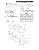
[0029] FIG. 1 is a perspective view of a multi-board desk according to a first exemplary embodiment.
[0030] FIG. 2 is a partial perspective view of a modification of a base desk plate of FIG. 1.
[0031] FIG. 3 is a vertical cross-sectional view partially illustrating a modification of an upper desk plate of FIG. 1.
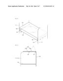
[0032] FIG. 4 is a partial perspective view of a modification of a lower desk plate of FIG. 1.
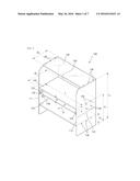
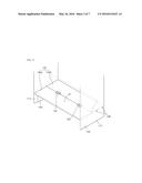
[0033] FIG. 5 is a perspective view of a multi-board desk according to a second exemplary embodiment.
[0034] FIG. 6 is a partial perspective view of an example in which a door is installed between a base desk plate and an upper desk plate of FIG. 5.
[0035] FIG. 7 is a partial perspective view illustrating an open state of the door of FIG. 6.
[0036] FIG. 8 is a partial perspective view illustrating a guide groove of FIG. 7 and a protrusion that is installed at a door and separated from the guide groove.
MODE OF THE INVENTION
[0037] Hereinafter, a multi-board desk will now be described more fully with reference to the accompanying drawings, in which exemplary embodiments of the inventive concept are shown. Like reference numerals in the drawings denote like elements.
[0038] FIG. 1 is a perspective view of a multi-board desk 100 according to a first exemplary embodiment.
[0039] Referring to FIG. 1, the multi-board desk 100 includes side plates 111 and 112, which are spaced apart from each other at a regular interval, and desk plates that are installed on the side plates 111 and 112 in multiple columns at different heights levels.
[0040] In detail, the side plates 111 and 112 may also be referred to as a left side plate 111 and a right side plate 112, both of which may be made of wood. The left side plate 111 and the right side plate 112 are spaced apart from each other at a regular interval and face each other. A space between the left side plate 111 and the right side plate 112 is determined based on a length L of a base desk plate 120 to be described below. Widths of the left side plate 111 and the right side plate 112 may be the same as or slightly less than a width W1 of the base desk plate 120, and heights of the left side plate 111 and the right side plate 112 may be the same as an installation height H2 of an upper desk plate 130 to be described below.
[0041] The desk plates include the base desk plate 120 and the upper desk plate 130 installed in multi columns at different heights levels. The base desk plate 120 may be installed at a height H1, for example, a height of about 68 to about 78 cm, at which a user may sit on a chair to use the multi-board desk 100, and the upper desk plate 130 may be installed at the height H2, for example, a height of about 110 to about 125 cm, at which the user may stand to use the multi-board desk 100.
[0042] The base desk plate 120 may be installed between the left side plate 111 and the right side plate 112 and the length L of the base desk plate 120 may range from about 90 to about 160 cm and the width W1 of the base desk plate 120 may range from about 60 to about 100 cm, but is not limited thereto.
[0043] The base desk plate 120 may be made of wood, and both end portions thereof in a lengthwise direction thereof may be respectively fixed to the left side plate 111 and the right side plate 112 by fixing members, for example, screws 128. The base desk plate 120 may be made of tempered glass, as described below.
[0044] An auxiliary plate 122 may be installed under the base desk plate 120 in parallel to the same by a certain distance D, for example, a distance ranging from about 8 to 15 cm. The auxiliary plate 122 may have the same size as the base desk plate 120 and may be made of wood. End portions of the auxiliary plate 122 in a lengthwise direction thereof are coupled to guide rails 124 that are respectively installed on an inner surface of the left side plate 111 and an inner surface of the right side plate 112, and along the guide rails 124, the auxiliary plate 122 may slide back and forth in a direction indicated by an arrow A of FIG. 1. The guide rails 124 may be respectively fixed to the left side plate 111 and the right side plate 112 by fixing members, for example, screws 129.
[0045] A computer and a monitor may be arranged on the base desk plate 120, and a keyboard may be arranged on the auxiliary plate 122. Also, documents, books, etc. for working or studying may be placed on the auxiliary plate 122.
[0046] The upper desk plate 130 is installed on the left side plate 111 and the right side plate 112 and may have the same size as the base desk plate 120. As illustrated in FIG. 1, a width W2 of the upper desk plate 130 may be less than the width W1 of the base desk plate 120, for example, may be about 5 to about 15 cm less than the width W1 of the base desk plate 120, such that the user sitting on a chair and using the base desk plate 120 may not bump his/her head against the upper desk plate 130. In other words, the base desk plate 120 may be projected frontwards about 5 to about 15 cm farther than the upper desk plate 130.
[0047] The upper desk plate 130 may be made of tempered glass, and both end portions thereof in a lengthwise direction may be fixed to upper surfaces of the left side plate 111 and the right side plate 112 by fixing members, for example, screws 138. As the upper desk plate 130 is made of tempered glass, a working space between the upper desk plate 130 and the base desk plate 120 may be well lighted. The upper desk plate 130 may be made of wood, as described below.
[0048] The desk plates may further include a lower desk plate 140 installed under the base desk plate 120. The lower desk plate 140 is installed at a height H3 at which the user may sit on the floor to use the multi-board desk 100, and the height H3 may preferably be about 30 to about 35 cm.
[0049] The lower desk plate 140 is installed between the left side plate 111 and the right side plate 112 and may have the same size as the base desk plate 120.
The lower desk plate 140 may be made of wood, and both end portions thereof in a lengthwise direction may be respectively fixed to the left side plate 111 and the right side plate 112 by fixing members, for example, screws 148.
[0050] Lighting devices 146 may be installed at a space between the lower desk plate 140 and the base desk plate 120 to light the space and may include light-emitting diodes (LED). The lighting devices 146 may be installed on the inner surfaces of the left side plate 111 and the right side plate 112, and although not illustrated, the lighting device 146 may be installed on a rear plate 150 installed at the back of the space between the left side plate 111 and the right side plate 112.
[0051] As described above, the multi-board desk 100 according to the first exemplary embodiment includes the base desk plate 120 and the upper desk plate 130 installed in multi columns at different heights levels, and thus, the user may sit on the chair and use the base desk plate 120 or may stand and use the upper desk plate 130 without moving to another location. Also, if the multi-board desk 100 further includes the lower desk plate 140 under the base desk plate 120, the user may sit on the floor to use the multi-board desk 100. Therefore, since the user may easily change a posture at one location while using the multi-board desk 100 without moving to another location, the user may stay healthy and may not fall asleep, and thus, working or studying efficiency may be improved.
[0052] Also, when the user needs to deal with a large amount of documents occupying a large space on the multi-board desk 100 that is a multi desk, the documents may be distributed on the base desk plate 120 and the upper desk plate 130, and thus, the user may efficiently work.
[0053] Hereinafter, various modified examples of the multi-board desk 100 according to the first exemplary embodiment will be described.
[0054] FIG. 2 is a partial perspective view of a modification of the base desk plate 120 of FIG. 1. FIG. 3 is a vertical cross-sectional view partially illustrating a modification of the upper desk plate 130 of FIG. 1. FIG. 4 is a partial perspective view of a modification of the lower desk plate 140 of FIG. 1.
[0055] Referring to FIG. 2, as described above, the base desk plate 120 may be made of tempered glass. In this case, it is difficult to fix the tempered glass to the left side plate 111 and the right side plate 112 by using screws, and thus, support members 126 for supporting the end portions of the base desk plate 120 in the lengthwise direction may be installed on the inner surfaces of the left side plate 111 and the right side plate 112. The support member 126 may have a plate shape, but is not limited thereto.
[0056] As described above, when the base desk plate 120 is made of tempered glass, the user may put documents or books, which are open, on the auxiliary plate 122 installed under the base desk plate 120 when working.
[0057] Referring to FIG. 3, as described above, the upper desk plate 130 may be made of wood. In this case, the upper desk plate 130 may be foldable to light the space between the upper desk plate 130 and the base desk plate 120.
[0058] In detail, the upper desk plate 130 may be separated into a front board 130a and a rear board 130b, and a rear end portion of the front board 130a and a front end portion of the rear board 130b may be coupled to each other by a first hinge 132, and a rear end portion of the rear board 130b and an upper end portion of the rear plate 150 may be coupled to each other by a second hinge 134.
[0059] Based on the above-described structure, when the user stands to use the upper desk plate 130, the front board 130a and the rear board 130b may be horizontally unfolded. When the user sits on the chair to use the base desk plate 120, if the front board 130a and the rear board 130b of the upper desk plate 130 are folded and stand as indicated by a two-point chain line of FIG. 3, an upper space of the base desk plate 120 may be lighted.
[0060] The space between the upper desk plate 130 and the base desk plate 120 may be lighted by fixing the upper desk plate 130 made of wood to the upper surfaces of the left side plate 111 and the right side plate 112 by the screws 138, as illustrated in FIG. 1, and by installing an LED lighting device (not shown) on a bottom surface of the upper desk plate 130 or an inner surface of the rear plate 150.
[0061] Referring to FIG. 4, when the user sits on the chair and uses the base desk plate 120, the user may feel uncomfortable because the lower desk plate 140 may prevent his/her legs from freely moving. Thus, the lower desk plate 140 may be foldable to solve the problem.
[0062] In detail, the lower desk plate 140 is separated into a front board 140a and a rear board 140b. Both end portions of the rear board 140b are fixed to the left side plate 111 and the right side plate 112 by using the screws 148, and a rear end portion of the front board 140a and a front end portion of the rear board 140b are coupled to each other by a hinge 142. Support members 144 for supporting both end portions of the front board 140a of the lower desk plate 140 in the lengthwise direction may be installed on the inner surfaces of the left side plate 111 and the right side plate 112. The support member 144 may have a plate shape, but is not limited thereto.
[0063] Based on the above-described structure, when the user sits on the floor to use the lower desk plate 140, the front board 140a and the rear board 140b may be horizontally unfolded. When the user sits on the chair to use the base desk plate 120, if the front board 140a is folded upwards and overlaps the rear board 140b of the lower desk plate 140 as indicated by a two-point chain line of FIG. 4, the legs of the user sitting on the chair are not obstructed by the lower desk plate 140.
[0064] Hereinafter, a multi-board desk according to a second exemplary embodiment will be described.
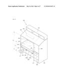
[0065] FIG. 5 is a perspective view of a multi-board desk 200 according to the second exemplary embodiment.
[0066] Referring to FIG. 5, the multi-board desk 200 according to the second exemplary embodiment includes side plates 211 and 212, which are spaced apart from each other at a regular interval, desk plates that are installed on the side plates 211 and 212 at different heights levels, and a compartment installed on an outer portion of any one of the side plates 211 and 212, for example, the side plate 212.
[0067] In detail, the side plates 211 and 212 may also be referred to as a left side plate 211 and a right side plate 212 and have the same structure as the left side plate 111 and the right side plate 112 in the first exemplary embodiment. Thus, detailed descriptions regarding the side plates 211 and 212 will be omitted.
[0068] The desk plates include a base desk plate 220 and an upper desk plate 230 installed in multi columns at different heights levels and may further include a lower desk plate 240 installed under the base desk plate 220. The base desk plate 220 is installed at a height H1, for example, a height ranging from about 68 to about 78 cm, at which the user sits on the chair and uses the multi-board desk 200, and the upper desk plate 130 is installed at a height H2, for example, a height ranging from about 110 to about 125 cm, at which the user stands and uses the multi-board desk 200. The lower desk plate 140 may be installed at a height H3, for example, a height ranging from about 30 to about 35 cm, at which the user sits on the floor and uses the multi-board desk 200.
[0069] The base desk plate 220 is installed between the left side plate 211 and the right side plate 212. The base desk plate 220 may be made of tempered glass, and support members 226 for supporting both end portions of the base desk plate 220 in a lengthwise direction thereof may be installed on inner surfaces of the left side plate 211 and the right side plate 212.
[0070] The base desk plate 220 may be made of wood, and in this case, as illustrated in FIG. 1, the end portions in the lengthwise direction thereof may be respectively fixed to the left side plate 211 and the right side plate 212 by fixing members, for example, screws.
[0071] An auxiliary plate 222 may be installed under the base desk plate 220 by a certain distance and may be parallel to the base desk plate 220. The auxiliary plate 222 may have the same size as the base desk plate 220 and may be made of wood. End portions of the auxiliary plate 222 in a lengthwise direction thereof may be respectively fixed to the left side plate 211 and the right side plate 212 by fixing members, for example, screws. Since functions of the auxiliary plate 222 are the same as those of the support plate 122 according to the first exemplary embodiment, detailed descriptions regarding the auxiliary plate 222 will be omitted.
[0072] As illustrated in FIG. 1, end portions of the auxiliary plate 222 in a lengthwise direction thereof are coupled to guide rails that are respectively installed on the inner surface of the left side plate 211 and the inner surface of the right side plate 212, and the support plate 222 may slide back and forth along the guide rails.
[0073] In order to prevent the user, who sits on the chair and uses the base desk plate 220, from bumping his/her head against the upper desk plate 230, the base desk plate 220 may be projected about 5 to about 15 cm farther from the upper desk plate 230. Also, like the base desk plate 220, the auxiliary plate 222 may be projected about 5 to about 15 cm farther from the upper desk plate 230.
[0074] The upper desk plate 230 may be made of wood or tempered glass and may be installed on the left side plate 211 and the right side plate 212. The end portions of the upper desk plate 230 in the lengthwise direction thereof may be fixed to the upper surfaces of the left side plate 211 and the right side plate 212 by fixing members such as screws. The upper desk plate 230 may extend toward an upper portion of a compartment to be described below, and in this case, a length of the upper desk plate 230 may be greater than a length of the base desk plate 220. Therefore, when the use stands to work and uses the upper desk plate 230, a large working space may be secured.
[0075] When the upper desk plate 230 is made of tempered glass, a working space between the upper desk plate 230 and the base desk plate 220 may be lighted, and when the upper desk plate 230 is made of wood, an LED lighting device 232 may be installed under the upper desk plate 230 such that the space between the upper desk plate 230 and the base desk plate 220 may be lighted. A rear plate 250 installed at the back of the space between the upper desk plate 230 and the base desk plate 220 may be a metallic plate including holes.
[0076] The upper desk plate 230 may slant in an upward direction from a front portion of the upper desk plate 230 to a rear portion thereof. As the upper desk plate 230 slants, a level of the user's eyes may be naturally adjusted according to physical conditions of the user standing and working, and thus, working efficiency is improved.
[0077] Also, a bookshelf 270 may be installed on a rear portion of the upper desk plate 230, and thus books, documents, or the like may be easily stored.
[0078] The lower desk plate 240 may be installed between the left side plate 211 and the right side plate 212 and may have the same size as the base desk plate 220. The lower desk plate 240 may be made of wood, and the end portions of the lower desk plate 240 in the lengthwise direction thereof may be respectively fixed to the left side plate 211 and the right side plate 212 by fixing members.
[0079] The lower desk plate 240 may be foldable. In detail, the lower desk plate 240 may be separated into a front board 240a and a rear board 240b, and end portions of the rear board 240b in the lengthwise direction thereof are fixed to the left side plate 211 and the right side plate 212 by screws, and the front board 240a may be coupled to the rear board 240b by a hinge 242. Support members 244 for supporting end portions of the front board 240a of the lower desk plate 240 in the lengthwise direction thereof may be installed on inner surfaces of the left side plate 211 and the right side plate 212. A structure of the lower desk plate 240 is the same as that of the lower desk plate 140 of FIG. 4, and its effects are also the same.
[0080] A lighting device 246 may be installed to light the space between the lower desk plate 240 and the base desk plate 220, and since the lighting device 246 is the same as the lighting device 146 described in the first exemplary embodiment, detailed descriptions thereof will be omitted.
[0081] The compartment may include drawers 260 and a cabinet 262, and the drawers 260 and the cabinet 262 may be installed on an outer surface of the right side plate 212. The drawers 260 may store stationery, documents, and the like, and the cabinet 262 may be used to store large-sized personal items. The reference numeral "264" denotes an outer plate of the drawers 260 and the cabinet 262.
[0082] The multi-board desk 200 having the above-described structure includes the base desk plate 120, the upper desk plate 130, and the lower desk plate 240 at different heights in multi columns and thus have the same effects as the multi-board desk 100 according to the first exemplary embodiment.
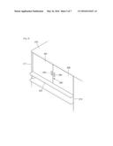
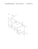
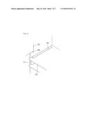
[0083] FIG. 6 is a partial perspective view of an example in which a door is installed between the base desk plate 220 and the upper desk plate 230 of FIG. 5. FIG. 7 is a partial perspective view illustrating an open state of the door of FIG. 6. FIG. 8 is a partial perspective view illustrating a guide groove of FIG. 7 and a protrusion installed at a door and separated from the guide groove.
[0084] Referring to FIGS. 6 to 8, doors 281 and 282 are installed between the base desk plate 220 and the upper desk plate 230 to open or close the space between the base desk plate 220 and the upper desk plate 230 in order to safely store a computer, personal items, or the like arranged between the base desk plate 220 and the upper desk plate 230, and the doors 281 and 282 may have locking devices 285.
[0085] In detail, the doors 281 and 282 are hinged doors and may also be referred to as a left door 281 and a right door 282. The left door 281 and the right door 282 may have handles 283 and 284. The handles 283 and 284 may respectively protrude from the left door 281 and the right door 282. However, as described below, when the left door 281 and the right door 282 are inserted into the space between the base desk plate 220 and the upper desk plate 230, the handles 283 and 284 may not be fully inserted into the left side plate 211 and the right side plate 212 due to interference and thus may preferably be concave grooves. The locking devices 285 are respectively installed on the left door 281 and the right door 282 to lock the same and may have various shapes.
[0086] When the left door 281 and the right door 282 are open, the left door 281 and the right door 282 go into the space between the base desk plate 220 and the upper desk plate 230 along the inner surfaces of left side plate 211 and the right side plate 212 such that the user may not be disturbed from working. To this end, guide grooves 287 having a certain depth and extending in a widthwise direction of the base desk plate 220 are formed in upper surfaces of the end portions of the base desk plate 220 in the lengthwise direction thereof, and protrusions 288 may be respectively formed on a lower side surface of the left door 281 and a lower side surface of the right door 282 such that the protrusions 288 may respectively move along the guide grooves 287. A front end portion of the guide groove 287 may be bent outwards at a right angle, and accordingly, when the left door 281 and the right door 282 are closed and pushed in opposite directions, the protrusions 288 may be located at bent portions of the guide grooves 287, and thus, the left door 281 and the right door 282 are not inserted into the space between the base desk plate 220 and the upper desk plate 230 even though they are pushed toward the space.
[0087] A guide groove (not shown) is formed in a lower surface of the upper desk plate 230, and protrusions (not shown) that are inserted into the guide groove formed in the lower surface of the upper desk plate 230 may be installed on an upper side surface of the left door 281 and an upper side surface of the right door 282. Based on this structure, the left door 281 and the right door 282 may move back and forth along the guide grooves 287, that is, in a direction indicated by an arrow B of FIG. 7.
[0088] As described above, as the doors 281 and 282 and the locking device 285 are formed between the base desk plate 220 and the upper desk plate 230, a computer, documents, personal items, or the like that need to be securely stored may be safely stored. Also, when the base desk plate 220 is used, the doors 281 and 282 are pushed into the space between the base desk plate 220 and the upper desk plate 230, and thus, the user may not be disturbed from working.
[0089] The doors 281 and 282 and the locking device 285 may also be applied to the first exemplary embodiment described with reference to FIG. 1.
[0090] It should be understood that exemplary embodiments described herein should be considered in a descriptive sense only and not for purposes of limitation. Descriptions of features or aspects within each exemplary embodiment should typically be considered as available for other similar features or aspects in other exemplary embodiments.
[0091] While one or more exemplary embodiments have been described with reference to the figures, it will be understood by those of ordinary skill in the art that various changes in form and details may be made therein without departing from the spirit and scope as defined by the following claims.
INDUSTRIAL APPLICABILITY
[0092] The one or more exemplary embodiments of the inventive concept may be applied to a multi-board desk in which multiple desk plates are installed at multiple levels.
User Contributions:
Comment about this patent or add new information about this topic:
| People who visited this patent also read: | |
| Patent application number | Title |
|---|---|
| 20190084390 | Vehicle Roof Base Frame |
| 20190084389 | Drive Cable Having a Plastics Cable Body |
| 20190084388 | FOLDING COVER APPLICABLE TO CARRIAGE |
| 20190084387 | INNER PANEL ASSEMBLY OF A VEHICLE DOOR |
| 20190084386 | VEHICLE DOOR |
Images included with this patent application:
 |  |
 |  |
 |  |
 |  |
| New patent applications in this class: | |
| Date | Title |
|---|---|
| 2015-01-22 | Latch assembly for multiple doors |
| 2014-05-22 | Image processing device and cover attachment structure |
| 2014-04-10 | Refrigerator and filler thereof |
| 2013-07-11 | Angle adjustment apparatus of image display module |
| 2012-04-12 | Cabinet for electronic equipment |
| Top Inventors for class "Supports: cabinet structure" | |
| Rank | Inventor's name |
|---|---|
| 1 | Yun-Lung Chen |
| 2 | Karl-Friedrich Laible |
| 3 | Jae Hoon Lim |
| 4 | Chen-Lu Fan |
| 5 | Wen-Tang Peng |