Patent application title: ELECTRONIC CIGARETTE AND MOUTHPIECE PART THEREOF
Inventors:
Qiuming Liu (Huizhou City, CN)
Qiuming Liu (Huizhou City, CN)
IPC8 Class: AA24F4700FI
USPC Class:
131329
Class name: Tobacco tobacco users' appliance
Publication date: 2016-05-26
Patent application number: 20160143365
Abstract:
The present invention relates to an electronic cigarette and mouthpiece
part thereof. The mouthpiece part includes within an inhaling shell: an
aerosol passage, a reservoir, an atomizing device, and a guiding device
for sealing the reservoir and guiding tobacco substance from the
reservoir to the atomizing device for vaporization without fluid leakage.
The guiding device includes a guiding plate and an absorption piece
laminating each other. Tobacco substance penetrates the guiding plate and
is absorbed and stored in the absorption piece for vaporization. The
electronic cigarette includes the mouthpiece part and a power source part
connecting each other. The electronic cigarette and mouthpiece part
thereof facilitate assembling, improve guiding tobacco substance, and
prevent fluid-leakage.Claims:
1. An electronic cigarette comprising: an inhaling shell; a reservoir
defined in the inhaling shell for storing tobacco substance; an atomizing
device positioned in the inhaling shell which comprises an atomizing cup
and an atomizer mounted in the atomizing cup; and a guiding device
disposed between the reservoir and the atomizing device for guiding
tobacco substance from the reservoir to the atomizing cup for
vaporization; wherein the atomizing cup comprises a bottom wall and an
annular sidewall both of which together enclose an atomizing chamber; a
pair of seats axially extends upwards from the annular side wall, and
each seat defines a fix groove opposite to the atomizing chamber; the
atomizer comprises an electric heat wire and an electric heat bar; the
electric heat wire winds around the electric heat bar and the atomizer is
mounted in the atomizing cup via the electric heat bar; the electric heat
bar extends both its opposite ends upwards; each of the opposite ends of
the electric heat bar respectively forms a vertical bar, and a lower
portion connected with both the opposite ends forms a horizontal bar; and
both of the vertical bars of the electric heat bar are respectively
supported along the fix groove by the seat, while the horizontal bar is
supported above the bottom wall in the atomizing chamber.
2. The electronic cigarette according to claim 1, wherein the atomizing cup substantially is an integral and inseparable cylinder; the electric heat bar substantially forms a "U" shape; each fix grooves is vertically formed along an inner wall of the seat in the atomizing chamber; the pair of fix grooves accordingly opposite to each other in the atomizing chamber, face and are communicated with the atomizing chamber; the inner wall of the seat forms an arc or a slope inner wall to support both the opposite ends of the heat bar.
3. The electronic cigarette according to claim 1, wherein the atomizing cup further defines a pair of wire-inserting holes therethrough; the pair of wire-inserting holes respectively vertically align to the fix grooves and extend through the bottom wall of the atomizing cup from an inner side in the atomizing chamber to a reverse outer side of the bottom wall; a center through hole are defined vertically through the bottom wall for heat dissipation; and a wire-cross groove is horizontally defined along the outer side the bottom wall and communicated with one of the wire-inserting hole.
4. The electronic cigarette according to claim 3, wherein the atomizing cup forms a pair of bases in the atomizing chamber from the bottom wall vertically extending upwards; each base aligns to and is located below the seat for supporting the lower portion of the electric heat bar; and each wire-inserting hole extends through each base; the electric heat bar is supported in the atomizing chamber on the pair of bases with its lower portion above the center through hole.
5. The electronic cigarette according to claim 3, further comprising an electrode assembly and a power source part for suppling an electric power to the atomizing device via the electrode assembly; wherein the electrode assembly comprises a first electrode and a second electrode with an insulating ring inserting therebetween; the first electrode comprises a cylindrical section and an opposite engaging section, the second electrode is fitted in the engaging section of the first electrode by inserting the insulating ring therebetween, the first electrode has the cylindrical section tightly fitted in the inhaling shell and forming a cylindrical chamber for holding the atomizing device therein.
6. The electronic cigarette according to claim 5, both ends of the electric heat wire respectively pass through the wire-inserting holes while the heat bar is mounted in the atomizing chamber with both its ends supported in the fixing grooves of the seats; one end of the electric heat wire passes through the corresponding wire-inserting hole and the wire-cross groove, extends back between an outer surface of the atomizing cup and the first electrode, and is tightly fixed in and electrically connected with the first electrode by means of the atomizing cup being tightly engaged in the first electrode by interference fit; the other end of the electric heat wire passes through the other wire-inserting hole and extends between the second electrode and insulating ring so as to electrically connect with the second electrode by means of the insulating ring being engaged in the second electrode by interference fit; whereby both ends of the electric heat wire are respectively electrically connected with the first electrode and second electrode in a gripping means instead of soldering means.
7. The electronic cigarette according to claim 1, wherein the guiding device comprises a guiding plate and an absorption piece horizontally overlaying each other face to face; the guiding device has a configuration and size adapted to an open end of the reservoir and seal the opening end of the reservoir; the guiding device is horizontally positioned at the open end of the reservoir; the absorption piece faces the atomizer in the atomizing cup, while the guiding plate faces the reservoir and contacts tobacco substance.
8. The electronic cigarette according to claim 7, wherein the guiding plate and the absorption piece substantially have the same shape, contact each other, and are tightly fitted in an inner wall of the reservoir at the open end thereof.
9. The electronic cigarette according to claim 7, wherein the guiding plate defines through guiding hole therein for voluntarily guiding liquid tobacco substance from the reservoir to the absorption piece; the guiding plate defines a main guiding hole in center of a circle shape thereof, and radially defines a plurality of secondary guiding holes around; the absorption piece is made from materials with adsorbing ability and heat-resistance which is able to absorb and store liquid like a sponge, and has relatively good temperature resistance to resist heat from the atomizer.
10. The electronic cigarette according to claim 9, wherein the liquid tobacco substance from the reservoir voluntarily flows through the main and secondary guiding holes and is well absorbed, spread and stored in the absorptions piece; the absorption piece has one side abutting against the guiding plate and the other reverse side against a top open end of the atomizing cup; the liquid tobacco substance stored in the absorption piece is able to be vaporized by the atomizer in the atomizing cup; the top open end of the atomizing cup is a top end of the annular side wall and opposite to the bottom wall of the atomizing cup, and is communicated with the atomizing chamber.
11. The electronic cigarette according to claim 7, wherein The atomizing cup is located below the guiding device; both ends of the heat bar upwards contact and vertically engage with the absorption piece; liquid tobacco substance stored in the absorption piece is transferred from the absorption piece to the heat bar for vaporization by the electric heat wire; the heat bar is supported by the seats, and both ends of the heat bar are respectively supported along the fix grooves by an inner wall of the seat, the heat bar is firmly and liably fixed in the atomizing cup with both ends firmly contacting and engaging with the absorption piece upwards; and the liquid tobacco substance is able to be voluntarily and liably transferred from the absorption piece to the heat bar for atomization.
12. The electronic cigarette according to claim 1, wherein the inhaling shell substantially is a cylinder with an open end and an opposite closed end, and defines the reservoir and an aerosol passage axially side by side therein; the aerosol passage is communicated with the atomizing cup; the closed end is used as an inhaling end the electronic cigarette for the user smoking, while the open end is used as a connecting end for engaging with a power source part; a suction hole is defined in the closed end and communicates with the aerosol passage whereby vapor mists vaporized from tobacco substance is able to be inhaled by the user by flowing along the passage and puffing through the smoke-flowsuction hole at the closed end of the inhaling shell.
13. The electronic cigarette according to claim 12, wherein the reservoir is integrated in the inhaling shell; an interval wall extends from the closed end of the inhaling shell and divides the inhaling shell into two parts side by side which respectively are the reservoir and the aerosol passage longitudinally parallel to each other; the interval wall has a first end to form a step towards the reservoir and extend to the closed end of the inhaling shell; the step constructs the suction hole communicated with the aerosol passage for the user to suck.
14. The electronic cigarette according to claim 13, wherein the interval wall is connected with the closed end of the inhaling shell to close a first end of the reservoir at the closed end of the inhaling shell, and has the other end thereof extending to a second end of the reservoir and engaging with the guiding device behind the open end of the inhaling shell.
Description:
CROSS-REFERENCE TO RELATED APPLICATIONS
[0001] This is a continuation-in-part of U.S. application Ser. No. 13/502,124, filed Apr. 13, 2012, which is a national phase of PCT Application No. PCT/CN2012/073664 filed on Apr. 9, 2012, which claims benefit of Chinese Patent Application No. 201220141170.8, filed on Apr. 1, 2012, the disclosure of which is incorporated by reference herein.
BACKGROUND OF THE INVENTION
[0002] 1. Field of the Invention
[0003] The present invention relates to a kind of electronic cigarette and a mouthpiece part thereof.
[0004] 2. Description of Related Art
[0005] A mouthpiece part of the existing electronic cigarette comprises in an opaque inhaling shell: a reservoir, an atomizing device with an electric heat wire and an atomizing cup, a long guiding tube for guiding tobacco substance from the reservoir to the atomizing device, and a mouthpiece cap at an end of the inhaling shell. Both ends of the electric heat wire are respectively associated with positive electrode and negative electrode by conductive wires.
[0006] However, such mouthpiece part of the existing electronic cigarette with the guiding tube extending into the reservoir, has problems such as complicated and inconvenient assembly, fluid leaking, and uncontrollability of guiding tobacco substance. Furthermore, the electric heat wire is pre-soldered or pre-fixed with conductive wires, and then is soldered to two electrodes of atomizing device, which results a miscellaneous and uneasy assembly process. Moreover, the atomizing cup consists of many parts, which adds to the difficulties of assembling electric heat wire. Finally, the inhaling shell is opaque, remaining tobacco substance in the reservoir is unobservable, which results unpleasant-flavor gas usually generated from burning electric heat wire after tobacco substance is exhausted.
[0007] Therefore, an improved electronic cigarette and a mouthpiece part thereof are desired which overcome the disadvantages of the prior art.
SUMMARY OF THE INVENTION
[0008] A main object of the present invention is to provide a mouthpiece part and an electronic cigarette, which facilitates assembly and manufacturing, and improves guiding tobacco substance, and prevents fluid-leakage.
[0009] A further object of the present invention is to provide a mouthpiece part and an electronic cigarette, in which tobacco substance remaining is observable.
[0010] To obtain the above object, a mouthpiece part of an electronic cigarette comprises an inhaling shell; within the inhaling shell, an aerosol passage, a reservoir for storing tobacco substance, an atomizing device which comprising an atomizing cup and an atomizer mounted in the atomizing cup, a guiding device set between the reservoir and atomizing device for sealing the reservoir and guiding tobacco substance from the reservoir to the atomizing cup for vaporization without fluid leakage. The guiding device comprises a guiding plate and an absorption piece laminating each other in such way that the guiding plate covers an open end of the reservoir and the absorption piece facing the atomizer in the atomizing cup. Thereby tobacco substance penetrates the guiding plate and is absorbed and stored in the absorption piece for vaporization.
[0011] In a preferable embodiment, the guiding plate defines at least one guiding hole for tobacco substance penetrating therethrough. Both the guiding plate and the absorption piece substantially has a circle shape with a cutout edge, the guiding hole in the guiding plate comprises a first main guiding hole in center of the circle and a plurality of secondary guiding holes at radial directions. The materials for the absorption piece are refractory wool, glass fiber, or heavy canvas.
[0012] In a preferable embodiment, the mouthpiece part further comprises an electrode assembly. The electrode assembly comprises a first electrode, a second electrode, and an insulating ring inserting therebetween. The first electrode comprises a cylindrical section inserting an open end of the inhaling shell for holding the atomizing device therein, and an engaging section for receiving the second electrode and insulating ring therein. The atomizer comprise an electric heat wire mounted in the atomizing cup with each end of the electric heat wire respectively passes through a corresponding wire-inserting hole in the atomizing cup. One end finally extends and is gripped between the first electrode and outer surface of the atomizing cup by interference fit therebetween, and the other end finally extends and is gripped between the second electrode and the insulating ring by interference fit therebetween. Thereby both ends of the electric heat wire respectively and electrically connected with the first electrode and the second electrode.
[0013] In a preferable embodiment, the whole or part of the mouthpiece part is transparent for observation. More preferably, the inhaling shell where the reservoir is located is transparent, so that remaining tobacco substance in the reservoir is observable.
[0014] To obtain the above object, the electronic cigarette comprises a mouthpiece part and a power source part electrically connected with each other. The mouthpiece part has the structure as described above.
[0015] In a preferable embodiment, the engaging section of the first electrode with the second electrode and insulating ring therein is electrically engaged with the power source part. Thereby the mouthpiece part is assembled with the power source part, and the first and second electrodes of the mouthpiece part are electrically connected with corresponding electrode of the power source part. The engaging section of the mouthpiece part is connected with the power source part by means of clipping, inserting, soldering, or thread engagement.
[0016] In a preferable embodiment, the power source part comprises a media player, an alarm clock, a compass, or a voice recorder therein.
[0017] Other objects, advantages and novel features of the invention will become more apparent from the following detailed description of a preferred embodiment thereof when taken in conjunction with the accompanying drawings, wherein:
BRIEF DESCRIPTION OF THE DRAWINGS
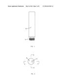
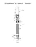
[0018] FIG. 1 is a front view of a mouthpiece part of an electronic cigarette in accordance with an embodiment of the present invention;
[0019] FIG. 2 is a top view of the mouthpiece part in FIG. 1;
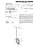
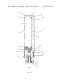
[0020] FIG. 3 is a cross-section view of the mouthpiece part of FIG. 2 along Line A-A;
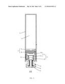
[0021] FIG. 4 is a cross-section view of the mouthpiece part of FIG. 2 along Line B-B;
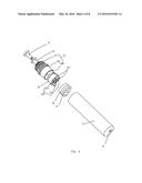
[0022] FIG. 5 is an exploded, perspective view of the mouthpiece part of FIG. 1;
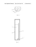
[0023] FIG. 6 is a front view of a guiding plate of the mouthpiece part in accordance with an embodiment of the present invention;
[0024] FIG. 7 is a cross-section view of an inhaling shell of the mouthpiece part in accordance with an embodiment of the present invention;
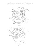
[0025] FIG. 8 is a perspective view of an atomizing cup of the mouthpiece part in accordance with an embodiment of the present invention;
[0026] FIG. 9 is another perspective view of the atomizing cup of FIG. 8;
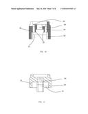
[0027] FIG. 10 is a cross-sectional view of the atomizing cup of FIG. 8;
[0028] FIG. 11 is another cross-sectional view of the atomizing cup of FIG. 8; and
[0029] FIG. 12 is a cross-sectional, partly exploded view of the electronic cigarette in accordance with an embodiment of the present invention.
DETAILED DESCRIPTION OF THE INVENTION
[0030] Referring to FIGS. 1 and 12, an electronic cigarette in accordance with an embodiment of the present invention, comprises a mouthpiece part 90 and a power source part 91. The power source part 91 is electrically connected with and supplies electric power to the mouthpiece part 90. Also referring to FIGS. 3-4 together, the mouthpiece part 90 comprises an inhaling shell 1, an atomizing device 2, a guiding device 3 and an electrode assembly 10 (see FIG. 1). The power source part 91 supplies the electric power to the atomizing device 2 of the mouthpiece part 90 by the electrode assembly 10.
[0031] Referring to FIGS. 2-7, the inhaling shell 1 substantially is a cylinder with an open end 19 and an opposite closed end 18, and defines a reservoir 11 and an aerosol passage 12 axially side by side therein. The closed end 18 is used as an inhaling end of the mouthpiece part 90 for the user smoking, and the open end 19 is used as a connecting end of the mouthpiece par 90 with the power source part 91. A suction hole 16 is defined in the closed end 18 and communicates with the aerosol passage 12 so that tobacco substance is vaporized into vapor mists to be inhaled by the user by flowing along the passage 12 and puffing through the suction hole 16 at the closed end 18 of the shell 1. This inhaling allows the user to absorb the scent-media in a vapor form together with the airflow inside the shell. In this way, the user is satisfied with a scent taste that mimics cigarette smoking. The closed end 18 of the inhaling shell 1 and the guiding device 3 respectively seal either end of reservoir 11.
[0032] In a preferable embodiment, the reservoir 11 for storing liquid tobacco substance is integrated in the shell 1. Preferably, the shell 1 integrally and longitudinally forms an interval wall 13 therein extending from its closed end 18 in such way to divide the shell 1 into two parts side by side which respectively are the reservoir 11 and the aerosol passage 12 longitudinally parallel to each other. The interval wall 13 has a first end 131 to form a step 130 towards the reservoir 11 and extend to the closed end 18 of the inhaling shell 1. The step 130 thus forms the suction hole 16 communicated with the aerosol passage 12 for the user to suck. The interval wall 13 is connected with the closed end 18 of the shell 1 to close the first end 110 of the reservoir 11 at the closed end 18 of the shell 1, and has the other end 132 thereof extending at a second end 112 of the reservoir 11 and engaging with the guiding device 3 behind the open end 19 of the shell 1. All or at least part of the inhaling shell 1 is transparent. Preferably, the section of the shell 1 where the reservoir 11 is located is transparent so that tobacco substance remaining in the reservoir 11 is observable.
[0033] The electrode assembly 10 comprises a first electrode 13 and a second electrode 14 of the atomizing device 2, and an insulating ring 15 inserting therebetween. As an embodiment, the first electrode 13 is configured as negative electrode of the atomizing device 2, accordingly, the second electrode 14 is configured as a positive electrode of the same. The first electrode 13 comprises a cylindrical section 130 and an opposite engaging section 131 with external thread thereon (not labeled). The second electrode 14 is fitted in the engaging section 131 of the first electrode 13 by inserting the insulating ring 15 therebetween. The first electrode 13 has the cylindrical section 130 tightly fitted in the inhaling shell 1 from the open end 19 thereof and forms a cylindrical chamber 1300 for holding the atomizing device 2 therein. The electrode assembly 10 of the mouthpiece part 90 is threadedly engaged with the power source part 91 in such manner that a bottom end of the second electrode 14 contact with the corresponding electrode of the power source part 91 and the engaging section 131 of the first electrode 13 threadedly and electrically engaged in the corresponding electrode of the power source part 91, so that the electronic cigarette is detachably assembled and an electric circuit thereof is set up.
[0034] The atomizing device 2 comprises an atomizer 21 and atomizing cup 22. The atomizer 21 comprises an electric heat wire 211 and an electric heat bar 212. The electric heat wire 211 winds around the electric heat bar 212 and the atomizer 21 is mounted in the atomizing cup 22 via the electric heat bar 212. Referring to FIGS. 8-11, the atomizing cup 22 is manufactured by an integrated molding process, and thus forms an integral and inseparable cup. The atomizing cup 22 has a top open end 228 and an opposite bottom wall 220, and further comprises a vertical annular sidewall 226. The bottom wall 220 and the annular side wall 226 of the atomizing cup 22 together enclose an atomizing chamber 221 therein, and the atomizing chamber 221 is communicated with the top open end 228 and the air passage 12. A pair of seats 222 longitudinally extends upwards from the annular side wall 226 of the atomizing cup 22 to a certain height, and each longitudinally defines a fix groove 2220 in the atomizing chamber 221 along an inner wall 2221 of the seat 222 for fixing the electric heat bar 212 therein. In this embodiment, the pair of seats 222 are located opposite to each other at a periphery of the annular sidewall 226, and located at the same diameter of the annular sidewall 226. Both fix grooves 2220 are accordingly opposite each other in the atomizing chamber 221, face and are communicated with the atomizing chamber 221. The inner wall 2221 of the seat 222 has an arc or a slope surface to define the fix groove 2220 extending upwards. In other embodiment, the inner wall 2221 of the seat 222 may be forms a slope directly to support the ends of the heat bar 212. The bottom wall 220 is circular.
[0035] A pair of wire-inserting holes 223 respectively aligned to the fix grooves 2220 are defined vertically through the bottom wall 220 of the atomizing cup 22 and extend from an inner side 2201 in the atomizing chamber to a reverse outer side 2202 of the bottom wall 220. In this embodiment, the atomizing cup 22 forms a pair of bases 227 from the inner side of the bottom wall 220 vertically extending upwards in the atomizing chamber 221 and each below the seat 222. Each wire-inserting hole 223 extends through each base 227. A center through hole 224 are defined in the bottom wall 220 for heat dissipation and extends from its inner side 2201 to its outer side 2202, and a wire-cross groove 225 is defined in the bottom wall 220 of the atomizing cup 22 opposite to the atomizing chamber 221 and communicated with one wire-inserting hole 223. Herein, the wire-cross groove 225 is defined in the outer side 2202 of the bottom wall 220. The atomizing cup 22 further vertically and downwards forms a bottom annular wall from the outer side 2202 of the bottom wall 220 in a relatively smaller diameter than that of the annular sidewall 226 so as to facilitate the assembly of atomizing cup 22 and the electrode assembly 10. The bottom annular wall and the annular sidewall 226 extend from the bottom wall 220 vertically to opposite directions. The wire-cross groove 225 horizontally goes through the bottom annular wall thus the bottom annular wall forms a cutout therein.
[0036] The heat bar 212 substantially forms a "U" shape, and comprises two ends 2120 upwards and a lower portion 2123 connected both ends 2120. In this embodiment, each end 2120 of the heat bar 212 substantially forms a vertical bar and the lower portion 2123 forms a horizontal bar. The atomizer 21 is mounted in atomizing chamber 221 of the atomizing cup 22. The lower portion or horizontal bar 2123 is supported on the bases 227 and across the bottom wall 220, and is located above the center hole 224 in the atomizing chamber 221; while both the ends namely the vertical bars 2120 are respectively supported along the fix grooves 2220 by the inner wall 2221 of the seat 222.
[0037] The electric heat wire 211 winds round the electric heat bar 212 with both ends of the electric heat wire 211 respectively through the wire-inserting holes 223 while the heat bar 212 is mounted in the fixing groove 2220 of the seats 222. One end of the electric heat wire 211 passes through the corresponding wire-inserting hole 223 and the wire-cross groove 225, extends back between the outer surface of the atomizing cup 22 and the first electrode 13, and is tightly fixed in and electrically connected with the first electrode 13 by means of the atomizing cup 22 being tightly engaged in the first electrode 13 by interference fit. The other end of the electric heat wire 211 passes through the other wire-inserting hole 223 and extends between the second electrode 14 and insulating ring 15 so as to electrically connect with the second electrode 14 by means of the insulating ring 15 being engaged in the second electrode 14 by interference fit. Therefore, both ends of the electric heat wire 221 are respectively electrically connected with the first electrode 13 and second electrode 14 by such gripping means instead of soldering means, which facilitates manufacturing and assembling the mouthpiece part 90. Furthermore, heat generated from the atomizer 21 is transmitted from the center through hole 224 to the power source part 91 for heat dissipation. The atomizing cup 22 is fitted in the inhaling shell 1 in such way that the atomizing cup 22 is fixed in the cylindrical chamber 1300 of the first electrode 13 and the first electrode 13 is inserted in the inhaling shell 1. The atomizing cup 22 has a configuration and size adapted to the cylindrical chamber 1300 of the first electrode 13, and is made from heat-stable material such as silica gel by an integrated molding process; thus the atomizing cup 22 is an integral and inseparable unit. The atomizing cup 22 is substantially shaped like a cylinder which preferably has a little bigger diameter than that of the cylindrical chamber 1300 of the first electrode 13, so that the atomizing cup 22 is tightly fitted in the cylindrical chamber 1300 of the first electrode 13 by interference fit. Such integral and inseparable structure of the atomizing cup 22 facilitates manufacturing and assembling the mouthpiece 90. The heat-resisting material of the atomizing cup 22 is beneficial to retain the temperature at outer surface of the inhaling shell 11 relatively low so that it will not be felt burning hand or mouth.
[0038] The guiding device 3 comprises a guiding plate 31 and an absorption piece 32 horizontally overlaying each other, which is used for guiding tobacco substance from the reservoir 11 to the atomizing cup 22 for vaporization without fluid leakage. The guiding device 3 has a configuration and size adapted to the inner wall of the inhaling shell 1 and the interval wall 13, namely the cross-section of the open end 112 of the reservoir 11, and is inserted in the inhaling shell 1 by interference fit in such way that the guiding plate 31 is horizontally positioned at the open end 112 of the reservoir 11, and the absorption piece 32 faces the atomizer 21 in the atomizing cup 22. Therefore, the guiding device 3 tightly seals tobacco substance in the reservoir 11.
[0039] In an illustrational embodiment, both the guiding plate 31 and the absorption piece 32 substantially have the same circle shape and are tightly fitted in the open end 112 of the reservoir 11. Furthermore, both the guiding plate 31 and the absorption piece 32 may have a cut-out edge according to cross-section of the open end of the reservoir 11. In this embodiment, the interval wall 13 is a straight plate, thereby, the guiding plate 31 and the absorption piece 32 are shaped in an arc, and the cutout is shaped as a straight line. The guiding plate 31 and the absorption piece 32 contact each other, have the same shape and horizontally laminated with to each other face to face with their peripheries aligned to each other.
[0040] The guiding plate 31 defines through guiding hole therein for voluntarily guiding liquid tobacco substance from the reservoir 11 to the absorption piece 32. In one embodiment, the guiding plate 31 defines a main guiding hole 311 in center of the circle shape thereof, and radially defines a plurality of secondary guiding holes 312. The absorption piece 32 may be made from such materials with adsorbing ability and heat-resistance which can absorb and store liquid like a sponge, and has relatively good temperature resistance to resist heat from the atomizer 21, such as refractory wool, glass fiber, or heavy canvas. Therefore, the liquid tobacco substance from the reservoir 11 voluntarily flows through the main and secondary guiding holes 311, 312 and is well absorbed, spread and stored in the absorptions piece 32. The absorption piece 32 has one side abutting against the guiding plate 31 and the other reverse side against the top open end 228 of the atomizing cup 22, so that the liquid tobacco substance stored in the absorption piece 32 can be vaporized below by the atomizer 21 in the atomizing cup 22. The atomizing cup 22 is located below guiding device 3. Both ends 2210 of the heat bar 212 upwards contact and vertically engage with the absorption piece 32. Thereby, liquid tobacco substance stored in the absorption piece 32 is transferred from the absorption piece 32 to the heat bar 212 for vaporization by the electric heat wire 211 therearound. The heat bar 212 is supported by the seats 222 in such way that both ends 2120 are respectively supported along the fix grooves 2220 by the inner wall 2221 of the seat 222, and is further supported on the bases 227 at its lower portion 2123 of the heat bar 212. Therefore, the heat bar 212 is firmly and liably fixed in the atomizing cup 22 with both ends 2120 of the heat bar 212 firmly contacting and engaging with the absorption piece 32 upwards, and accordingly, the liquid tobacco substance can be voluntarily and liably transferred from the absorption piece 32 to the heat bar 212 for atomization. Such guiding device 3 facilitates manufacturing and assembling the mouthpiece part 90, well guides tobacco substance from the reservoir 11 to the atomizing device 2 for vaporization, and well prevents tobacco substance being leaked out.
[0041] Referring to FIG. 12 again, the electronic cigarette in accordance with the embodiment of the present invention, comprises the mouthpiece part 90 and the power source part 91 which are connected together by electrode assembly 10. It is understood that the mouthpiece part 90 and the power source part 91 may be connected by means of clipping, inserting or soldering connection instead of threaded engagement. The power source part 91 comprises a power supply 911, controlling board 912, lighting indicator 913, end cap 914, a first power electrode frame 915, a second power electrode 916, and an insulating washer 917.
[0042] The power supply 911 is rechargeable or non-rechargeable power source to supply electric power to the electronic cigarette. The controlling board 912 controls the atomizing device 2 or other electronic elements working. The indicator 913 is electrically connected to the controlling board 912 and indicates a working mode. End cap 914 as a viewing window is sealed at end of the power source part 91. The first electrode 13 has the threaded section electrically and threadedly engaged in the first power electrode frame 915. The second power electrode 916 is fitted in the first electrode frame 915 by inserting the insulating washer 917 therebetween. Thereby, the mouthpiece part 90 is assembled to the power source part 91 with first electrode 13 of atomizer 2 electrically connected with the first power electrode frame 915, and the second electrode 14 of the atomizer 2 electrically contacts with the second power electrode 916. Therefore, the power source part 91 is able to energize the atomizer 21.
[0043] The power source part 91 further comprises a voice recorder 92. The voice recorder 92 comprises a microphone 921 and a receiver 922 for holding the voice recorder 92 in the power source part 91. The microphone 921 is electrically connected to the controlling circuit 912. Therefore, the e-cigarette has voice-recorded function. It understood that the e-cigarette can further comprise a media player, an alarm clock, and a compass.
[0044] In a preferable embodiment, the electronic cigarette of the present invention is one-off e-cigarette.
[0045] While the invention has been described in conjunction with specific embodiments, it is evident that numerous alternatives, modifications, and variations will be apparent to those skilled in the art in light of the forgoing descriptions. The scope of this invention is defined only by the following claims.
User Contributions:
Comment about this patent or add new information about this topic:
Images included with this patent application:
 |  |
 |  |
 |  |
 |  |
 |
| Similar patent applications: | |
| Date | Title |
|---|---|
| 2016-05-12 | Electronic cigarette with improved safety |
| 2015-12-24 | Electronic-cigarette filter |
| 2016-03-03 | Tabletop automatic cigarette-making machine |
| 2016-03-17 | Electronic cigarette |
| 2016-03-31 | Cigarette butt extinguishing and disposing apparatus |
| New patent applications in this class: | |
| Date | Title |
|---|---|
| 2022-05-05 | Aerosol delivery device having a resonant transmitter |
| 2022-05-05 | Aerosol generating device and operating method therefor |
| 2022-05-05 | Electronic smoking device |
| 2022-05-05 | Flavor dispenser apparatus |
| 2022-05-05 | Electronic cigarette atomization assembly and manufacturing method therefor |
| New patent applications from these inventors: | |
| Date | Title |
|---|---|
| 2016-04-28 | Electronic cigarette |
| 2016-03-17 | Electronic cigarette and its sucking rod |
| 2015-10-22 | Electronic cigarette |
| 2015-07-30 | Connecting head of an electronic cigarette and electronic cigarette |
| 2015-07-16 | Electronic cigarette and assembly method of atomizer thereof |
| Top Inventors for class "Tobacco" | |
| Rank | Inventor's name |
|---|---|
| 1 | Qiuming Liu |
| 2 | Munmaya K. Mishra |
| 3 | Qiuming Liu |
| 4 | Stephen Benson Sears |
| 5 | William R. Sweeney |