Patent application title: Drilling Rig
Inventors:
Fred L. Fortson (Tomball, TX, US)
Joseph A. Nichols (The Woodlands, TX, US)
Americo B. Garcia (Houston, TX, US)
IPC8 Class: AE21B702FI
USPC Class:
52121
Class name: Static structures (e.g., buildings) mechanism operated relatively movable shaft assembly longitudinally extensible by flexible drive or hoist
Publication date: 2016-05-12
Patent application number: 20160130877
Abstract:
Methods and systems are disclosed for a drilling rig that includes a
mast, such as a telescoping mast. The mast has at least three sections,
namely a top section, one or more intermediate sections that constitute
the intermediate section, and a bottom section. Further, the drilling rig
also includes a substructure that is removably attached to the mast. That
is, the drilling rig may be attached at its bottom section to the drill
floor of the substructure, which has components on and below it. The
drill floor has an adjustable height through contact with at least one
power source, such as mechanical (e.g., hydraulic, pneumatic, etc.),
electrical, and combinations thereof. Further still, the drilling rig is
transportable in a single load as opposed to having to transport the
drilling rig on multiple loads on multiple trucks.Claims:
1. A drilling rig comprising: a mast comprising at least three sections
and a top drive; and a substructure removably attached to the mast, the
substructure comprising a drill floor having an adjustable height through
contact with at least one power source, wherein the mast is transportable
in a single load, and the substructure is transportable in another single
load.
2. The drilling rig of claim 2, wherein the drilling rig is walkable.
3. The drilling rig of claim 3, wherein the substructure further comprises a plurality of shoes, where a first set of shoes in the plurality is connected to a first cross beam of a skid, and a second set of shoes in the plurality is connected to a second cross beam of the skid.
4. The drilling rig of claim 3, wherein the plurality of shoes selectively rotates to either any angle or any predetermined angle.
5. The drilling rig of claim 3, wherein the drilling rig comprises a positional displacement of 60 feet/hour.
6. The drilling rig of claim 1, wherein the substructure further comprises one or more cantilevered beams connected to a perimeter of the drill floor.
7. The drilling rig of claim 6, wherein the one or more cantilevered beams are angularly adjustable to facilitate co-planarity with the drill floor and retractability.
8. The drilling rig of claim 6, wherein the substructure further comprises a member selected from a group consisting of a driller's cabin, a tool house, and combinations thereof located on one or more cantilevered beams.
9. The drilling rig of claim 1, wherein the at least one power source is connected integrally, externally or both to the substructure, and wherein the at least one power source is mechanical, electrical, or combinations thereof.
10. The drilling rig of claim 1, wherein the substructure further comprises legs having first ends and second ends, wherein the first ends are connected to the drill floor, and a first set of the second ends are connected to a first cross beam of a skid, and a second set of the second ends are connected to a second cross beam of the skid.
11. The drilling rig of claim 10, wherein the substructure further comprises one or more cross beams that transversely connect the first beam to the second beam, wherein the one or more cross beams are optionally removable and optionally adjustable in position along the skid.
12. The drilling rig of claim 1, wherein the drilling rig has an approximate 500,000 pound setback capacity.
13. The drilling rig of claim 1, wherein the substructure has a weight of approximately 135,000 pounds or less.
14. The drilling rig of claim 1, wherein the top drive is reeved prior to and during transport of the drilling rig.
15. The drilling rig of claim 1, wherein the mast comprises a telescoping mast having at least three sections comprising a bottom section, a top section, and one or more intermediate sections therebetween, wherein a variable line interconnects the bottom section to one of the one or more intermediate sections, and a fixed line connects a group of sections, wherein the group comprises at least one of the one or more intermediate sections and two more sections.
16. The drilling rig of claim 15, wherein the one or more intermediate sections comprise a series of interconnected intermediate sections, wherein at least a bottommost intermediate section is connected to the bottom section and at least a topmost intermediate section is connected to the top section.
17. The drilling rig of claim 15, wherein the variable line comprises a winch and winch line.
18. The drilling rig of claim 1, wherein the mast comprises a telescoping mast having at least three sections comprising a bottom section, a top section, and one or more intermediate sections therebetween, wherein the telescoping mast comprises lines to simultaneously raise or lower heights of both the bottom section connected to one of the one or more intermediate sections, and the one or more intermediate sections connected directly or indirectly to the top section.
19. The drilling rig of claim 18, wherein the lines comprise a first line that is variable and one or more fixed lines that interconnect the one or more intermediate sections to the top section.
20. A method for assembling a drilling rig, the method comprising: receiving a drilling rig, wherein the drilling rig comprises: a telescoping mast having a reeved top drive, wherein the telescoping mast is transportable in a single load; and a substructure having a drilling floor and an adjustable height through contact with at least one power source, wherein the substructure is transportable in another single load; and securing the telescoping mast to the substructure.
21. The method of claim 20, further comprising raising or lowering the telescoping mast having a bottom section, one or more intermediate sections, and a top section, wherein the raising or the lowering comprises simultaneously raising or lowering heights of both the bottom section connected to a bottommost section of the one or more intermediate sections, and a topmost section of the one or more intermediate sections connected to the top section, wherein the bottommost section and the topmost section are a same section if there is only one of the one or more intermediate sections.
22. A method for telescoping a telescoping mast, the method comprising: adjusting a tensioning force of a variable line connected to a bottom section of the telescoping mast, wherein the telescoping mast further comprises one or more intermediate sections and a top section, wherein the variable line is operably connected to both a first side of the bottom section and proximate to a bottommost section of the one or more intermediate sections; and moving, simultaneously, the bottom section, the one or more intermediate sections, and the top section, in response to the adjusting, wherein a fixed line connects both proximate to a top of and on an opposite side of the bottom section with another top of one of the one or more intermediate sections and a bottom of either another one of the one or more intermediate sections or the top section.
Description:
FIELD OF DISCLOSURE
[0001] This disclosure generally relates to drilling rigs transportable in two loads with a reeved top drive in the mast, such that the drilling rig is relatively light yet robust, easily transported in commerce from a governmental licensing requirement, quickly assembled, as well as additional functionalities and benefits.
BACKGROUND
[0002] Drilling rigs create subterranean holes, including those subsea, and house equipment for conducting drilling operations for water, oil, natural gas, minerals, and other extractable substances existing in solid, liquid or gas state(s). Drilling rigs may be stationary or mobile, and in the case of the former, are permanent land or marine-based structures, such as oil platforms also known as "offshore oil rigs," regardless whether they actually contain a drilling rig. Moreover, drilling rigs may be walkable. What remains troublesome, however, is the compactability or retractability of drilling rigs comprising a mast and a substructure. For one, transport of drilling rigs generally requires multiple loads of the disassembled drilling rig's components before assembly at or for the worksite. Adding to that problem are the weight, height and width of the drilling rig's components. That is, local, state, and/or federal governmental licensing requirements (e.g., permits) may restrict the licensed use of conduits of commerce (e.g., roads, bridges, waterways, etc.) based on weights, heights, and widths of loads on vehicles, such as trucks, boats, etc. Such restrictions, if any licensed use is even permitted, may exist and/or be enforced, for instance, in the name of public health and safety. In addition to licensing restrictions, additional loads, whether oversized in any regulated metric or not, for transporting drilling rigs increases transportation (e.g., fuel, truck(s), etc.) and manpower costs. And, further to additional manpower costs, substantial time is required in rigging up a drilling rig's components that arrive disassembled at the worksite in multiple loads. Thus, the foregoing may evince perceived problems existing in current state of the art.
SUMMARY OF THE INVENTION
[0003] In one embodiment, the drilling rig may include a mast, such as a telescoping mast, that has at least three sections, namely a top section, one or more intermediate sections that constitute the intermediate section, and a bottom section. Further, the drilling rig may also include a substructure that is removably attached to the mast. That is, the drilling rig may be attached at its bottom section to the drill floor of the substructure, which has components on and below it. The drill floor has an adjustable height through contact with at least one power source, such as mechanical (e.g., hydraulic, pneumatic, steam, etc.), electrical, and combinations thereof. Further still, the mast, optionally having a reeved top drive before transit for easy assembly at a destination point, is transportable in a single load. The substructure is also transportable in another single load.
[0004] In another embodiment, there exists a method for assembling a drilling rig. The method may include receiving a reeved mast transportable in a single load and a substructure transportable in another load for easy assembly. The drilling rig may also include a telescoping mast having a reeved top drive, and a substructure having a drilling floor and an adjustable height through contact with at least one power source. Further, the method may include securing the telescoping mast to the substructure.
[0005] In another embodiment, there exists a method for telescoping a telescoping mast. The method may include adjusting a tensioning force of a variable line connected to a bottom section of the telescoping mast, wherein the telescoping mast further comprises one or more intermediate sections and a top section, wherein the variable line is operably connected to both a first side of the bottom section and proximate to a bottommost section of the one or more intermediate sections. Further, the method may include moving, simultaneously, the bottom section, the one or more intermediate sections, and the top section, in response to the adjusting, wherein a fixed line connects both proximate to a top of and on an opposite side of the bottom section with another top of one of the one or more intermediate sections and a bottom of either another one of the one or more intermediate sections or the top section.
BRIEF DESCRIPTION OF THE DRAWINGS
[0006] So that the manner in which the above recited features, advantages and objects of the present invention are attained and can be understood in detail, a more particular description of the invention, briefly summarized above, may be had by reference to the embodiments thereof which are illustrated in the appended drawings.
[0007] It is to be noted, however, that the appended drawings illustrate only typical embodiments of this disclosure and are therefore not to be considered limiting of its scope, for the disclosure may admit to other equally effective embodiments.
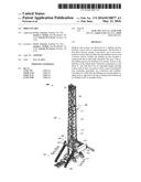
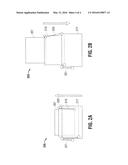
[0008] FIG. 1A depicts an example embodiment of a mast removably connected to the substructure in accordance with the disclosed methods and apparatuses.
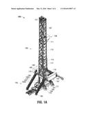
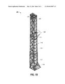
[0009] FIG. 1B depicts an example embodiment of a mast in accordance with the disclosed methods and apparatuses.
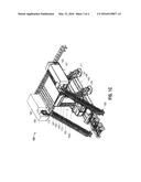
[0010] FIG. 1C depicts an example embodiment of a substructure in accordance with the disclosed methods and apparatuses.
[0011] FIG. 2A depicts an example embodiment of a retracted view of telescoping mast in accordance with the disclosed methods and apparatuses.
[0012] FIG. 2B depicts an example embodiment of an expanded view of telescoping mast in accordance with the disclosed methods and apparatuses.
DETAILED DESCRIPTION OF THE EMBODIMENTS
[0013] The following is a detailed description of example embodiments of the invention depicted in the accompanying drawings. The embodiments are examples and are in such detail as to clearly communicate the invention. However, the amount of detail offered is not intended to limit the anticipated variations of embodiments; on the contrary, the intention is to cover all modifications, equivalents, and alternatives falling within the spirit and scope of the present invention as defined by the appended claims. The detailed descriptions below are designed to make such embodiments obvious to a person of ordinary skill in the art.
[0014] In addition, directional terms, such as "above," "below," "upper," "lower," "front," "back," "top," "intermediate," "bottom," etc., are used for convenience in referring to the accompanying drawings. In general, "above," "upper," "upward," "top," and similar terms refer to a direction away the earth's surface, and "below," "lower," "downward," "bottom," and similar terms refer to a direction toward the earth's surface, but is meant for illustrative purposes only, and the terms are not meant to limit the disclosure.
[0015] Generally disclosed are apparatuses and methods for transporting and assembling a drilling rig, which may include a mast, optionally reeved before or after transport, and a substructure for removably connecting to the mast. The mast, optionally in a reeved state and/or telescoping, may be transported in a single load and the substructure may be transported in another single load. In various, example embodiments, the substructure may have a retracted height of ten feet, such as during transport. The substructure may have an expanded height of twenty-six feet, such as during drilling. The mast may add another one hundred and forty-three feet or so in height when assembled with the expanded substructure.
[0016] With reference to FIG. 1A, disclosed are drilling rig apparatuses and methods of assembling and usage of the same. In various example embodiments discussed below, the drilling rig 100 or apparatus 100, referenced interchangeably, may include a substructure 155. The substructure 155 may include various components, some of which are expressly discussed below, but any non-discussion does not preclude the possible presence of other components known to enable the drilling rig 100 or any drilling rig for that matter. For more convenient viewing, FIGS. 1B and 1C show what is already depicted in FIG. 1A; these enlarged views show the mast 105 in FIG. 1B removably detached from the substructure 155 shown in FIG. 1C, wherein such a disassembled state may be the case during transport of the optionally reeved mast 105 and the substructure 155, each component 105, 155 constituting a single load on the back of a truck or other vehicle; that is, for instance, the mast 105 may be a single load on one truck and the substructure 155 may be another single load on another truck.
[0017] The substructure 155 may include a drill floor 165, which has an adjustable height through contact with at least one power source 173, such as mechanical (e.g., hydraulic, pneumatic, steam, etc.), electrical, and combinations thereof. Power source(s), such as 173, in and for the disclosed drilling rig 100 may be integral, external, or a combination thereof. The substructure 155 may further include a skid 160, which may be spread apart through use of at least two cross beams, such as a first cross beam 161 and a second cross beam 162. Optionally interspaced between cross beams, such as the first cross beam 161 and the second cross beam 162, are removably or integrally attached one or more additional cross beams that transversely connect the first cross beam 161 and the second cross beam 162. Such additional cross beams are optionally adjustable in position along the skid 160, such as in latitudinal and/or longitudinal position(s) within one or more tracks or other mechanism for adjustably connecting the additional cross beams to the skid 160.
[0018] The substructure 155 may include legs 163 connected to the drill floor 165. Each of the legs 163 has a first end 163a and a second end 163b, wherein each first end 163a may be connected to the drill floor 165 and each second end 163b may be connected to one of the cross beams, such as the first cross beam 161 or the second cross beam 162. Like the drill floor 165, the plurality 163 of legs may be constructed of shape beam or other suitable material. The legs 163 may include a hydraulic lock in system or other mechanically and/or electronically driven power source. Particularly in a walkable embodiment of the drilling rig 100, a plurality of shoes, one being labeled as shoe 177, may be connected to either the first cross beam 161 or the second cross beam 162. In one embodiment, the plurality of shoes includes two shoes, such as shoe 177, spaceably connected to the first cross beam 161 and two more shoes, such as shoe 177, spaceably connected to the second cross beam 162; that is, the skid 160 is connected to two pairs of shoes. In other non-depicted embodiments, less or more than two pairs of shoes are connected to the skid 160. The plurality of shoes, such as shoe 177, may selectively rotate, upon execution of enabling logic reduced to hardware and/or software, to either any angle or any predetermined angle so that the drilling rig 100 walks in a direction manually or remotely chosen. The disclosed walkable drilling rig 100 may exhibit a positional displacement of 60 feet/hour or less.
[0019] In addition to the drill floor stairs 185, the substructure 155 may include one or more cantilevered beams 167 connected to a perimeter of the drill floor 165. The one or more cantilevered beams 167 are angularly adjustable to facilitate co-planarity with the drill floor 165 and retractability, wherein the latter may be desired during transport of the drilling rig 100. Such one or more cantilevered beams 167 may serve as a foundation for one or more driller's cabin(s), tool house(s), and combinations thereof, collectively referenced as 183 in the FIGS. 1A and 1C. A stand pipe manifold 180 may be located on the tool house 183 and adjacent to a deadline anchor that may be mounted in the bottom section 117 of the mast 105. The substructure 155 may also include drill floor wings 170, which are optionally removable for narrower loads. Drawworks 175 may be tailboarded on top of the skid 160 with a truck.
[0020] Turning now to the mast 105 that is removably connectable to the substructure 155 of the drilling rig 100, the mast 105 may include at least three sections, namely a top section 107, an intermediate section 113 that may include one or more intermediate sections, and a bottom section 117, wherein the bottom section 117 is the section that is removably connected to the substructure 155. The mast 105, such as in the top section 107, may include a top drive, which may be reeved or strung up before and during transport. In such a case, relatively quick assembly results when removably connecting the mast 105 and the substructure 155 to form the drilling rig 100 because many hours--about eight hours in some estimates--is saved in not having to reeve or string up the top drive. In the assembled state, the drilling rig 100 may have an approximated 500,000 pound setback capacity. The mast 105 may weigh approximately 150,000 pounds with the reeved top drive or approximately 120,000 pounds without the top drive. The substructure 155 may weigh approximately 135,000 pounds or less, such as approximately 125,000 pounds.
[0021] In optional, example embodiments, the mast 105 may include a kingpin 121 and/or a mast racking board 109, which may have an adjustable diving board 109 to allow closer access to the well center. Additionally and alternatively, the mast 105 may include one or more reversible locking mechanisms 111, 115 in order to securely and adjustably maintain any selected position of the mast's 105 sections 107, 113, 117 during use, operation, or transport of the assembled or disassembled drilling rig 106. The mast 105 may also include a framed braced 119, such as an A-frame, for connecting to the substructure 155. In particular, the A-framed brace 119 permits increased working room around the well. The built-in A-framed brace's 119 legs may be hooked to hydraulic cylinder(s), which, when activated, may raise and/or lower the A-framed brace's 119 legs.
[0022] In one example embodiment and with reference turning to FIGS. 2A and 2B, the mast 105 shown in FIG. 1 may be a telescoping mast 205. The telescoping mast 205 may have at least three sections 207, 213, 217 comprising a bottom section 217, a top section 207, and one or more intermediate sections therebetween to form the intermediate section 213, wherein a variable line 221 interconnects the bottom section 217 to one of the one or more intermediate sections 213, and a fixed line 225 connects a group of sections, wherein the group comprises at least one of the one or more intermediate sections 213 and two more sections 207, 213, 217. Further, the one or more intermediate sections 213 of the drilling rig may include a series of interconnected intermediate sections, wherein at least a bottommost intermediate section is connected to the bottom section 217 and at least a topmost intermediate section is connected to the top section 207. The variable line 221 of the drilling rig may be made possible through use of a winch and a winch line, collectively referred in FIGS. 2A and 2B as 221, running therethrough. FIGS. 2A and 2B are the same except that FIGS. 2A shows the telescoping mast 205 in a retracted state as the upward arrow depicts as being the only possible movement direction, and FIGS. 2B shows the telescoping mast 205 in an expanded state as the downward arrow depicts as being the only possible movement direction.
[0023] In another example embodiment, the telescoping mast 205 has at least three sections 207, 213, 217 that include a bottom section 217, a top section 207, and one or more intermediate sections 213 therebetween, wherein the telescoping mast 205 comprises lines 221, 225 to simultaneously raise or lower heights of both the bottom section 217 connected to one of the one or more intermediate sections 213, and the one or more intermediate sections 213 connected directly or indirectly to the top section 207. The lines of the drilling rig may include a first line 221 that is variable and one or more fixed lines 225 that interconnect the one or more intermediate sections 213 to the top section 207. Although the Figures show the mast 105, 205 as having one intermediate section for the intermediate section 213, the intermediate section 213 may include, in other example embodiments, one, two, three, or more intermediate sections, which collectively comprise the intermediate section 213. In this non-depicted scenario of more than one intermediate sections for the intermediate section 213, one or more fixed lines 225, as previously discussed, may exist. For instance, the same fixed line 225 or at least two fixed lines 225 may be used in an example embodiment that has two intermediate sections for the intermediate section 213, wherein all sections 207, 213, 217 are connected by the one or more fixed lines 225.
[0024] Although the foregoing provides an enabling discussion of the disclosed methods and apparatuses, a dedicated discussion now ensues with particular emphasis on methodologies. Disclosed is a method for assembling a drilling rig. The method includes receiving a reeved mast that is transportable in a single load and a substructure that is transportable in another single load, wherein the drilling rig may include a telescoping mast having a reeved top drive, and may also include a substructure having a drilling floor and an adjustable height through contact with at least one power source. Furthermore, the method may include securing the telescoping mast to the substructure. Regarding telescoping, that is, raising or lowering of the telescoping mast, the telescoping mast may have a bottom section, one or more intermediate sections, and a top section, wherein the raising or the lowering may include simultaneously raising or lowering heights of both the bottom section connected to a bottommost section of the one or more intermediate sections, and a topmost section of the one or more intermediate sections connected to the top section, wherein the bottommost section and the topmost section are a same section if there is only one of the one or more intermediate sections.
[0025] Additionally and alternatively, disclosed are methods of telescoping a telescoping mast includes adjusting a tensioning force of a variable line connected to a bottom section of the telescoping mast, wherein the telescoping mast further comprises one or more intermediate sections and a top section, wherein the variable line is operably connected to both a first side of the bottom section and proximate to a bottommost section of the one or more intermediate sections. Furthermore, the method of telescoping may include moving simultaneously the bottom section, the one or more intermediate sections, and the top section, in response to the adjusting, wherein a fixed line connects both proximate to a top of and on an opposite side of the bottom section with another top of one of the one or more intermediate sections and a bottom of either another one of the one or more intermediate sections or the top section.
[0026] While the foregoing is directed to example embodiments of the disclosed invention, other and further embodiments of the invention may be devised without departing from the basic scope thereof, and the scope thereof is determined by the claims that follow.
User Contributions:
Comment about this patent or add new information about this topic:
Images included with this patent application:
 |  |
 |  |
 |
| New patent applications in this class: | |
| Date | Title |
|---|---|
| 2016-12-29 | Telescopic mast |
| 2014-10-23 | Maximum strength, reduce weight telescoping mast with interlocking structural elements |
| 2014-09-18 | Telescoping derrick |
| 2012-11-08 | Retractable column and method of forming |
| 2012-05-10 | Payload mast |
| Top Inventors for class "Static structures (e.g., buildings)" | |
| Rank | Inventor's name |
|---|---|
| 1 | Darko Pervan |
| 2 | Gregory F. Jacobs |
| 3 | Husnu M. Kalkanoglu |
| 4 | Ronald P. Hohmann, Jr. |
| 5 | Mark Cappelle |