Patent application title: SENSOR UNIT, SENSOR SET, SPORTS EQUIPMENT, AND MOUNTING METHOD OF SENSOR UNIT
Inventors:
Yuya Ishikawa (Chino-Shi, JP)
IPC8 Class: AA63B2400FI
USPC Class:
473223
Class name: Practice swingable implement or indicator associated with swingable implement with electrical sensor or electrical indicator integral with or attachable to swingable implement
Publication date: 2016-05-12
Patent application number: 20160129306
Abstract:
A sensor unit is mounted on a golf club which is one of sports
equipments, and detects an inertial amount generated by a swing. In the
sensor unit, a Z-axis serving as a detection axis of the inertial amount
generated along a direction orthogonal to a surface located on the golf
club side when the sensor unit is mounted on the golf club is set to
extend along a direction S of the swing.Claims:
1. A sensor unit which is mounted on a sports equipment so as to detect
an inertial amount generated by a swing, wherein a detection axis of the
inertial amount generated along a direction orthogonal to a surface
located on the sports equipment side when the sensor unit is mounted on
the sports equipment is set to extend along a direction of the swing.
2. The sensor unit according to claim 1, wherein the sensor unit has multiple detection axes, and wherein one of the detection axes is set to extend along the direction of the swing, and the other one of the detection axes is set to extend along an extending direction of a shaft of the sports equipment.
3. A sensor unit which is mounted on a sports equipment so as to detect an inertial amount generated by a swing, wherein a surface located on the sports equipment side when the sensor unit is mounted on the sports equipment is set to be a surface orthogonal to a direction of the swing.
4. A sensor unit which is mounted on a sports equipment so as to detect an inertial amount generated by a swing, wherein a detection axis of the inertial amount generated along a direction orthogonal to a surface located on the sports equipment side when the sensor unit is mounted on the sports equipment is set to extend along a direction orthogonal to a hitting surface of the sports equipment.
5. The sensor unit according to claim 4, wherein the sensor unit has multiple detection axes, and wherein one of the detection axes is set to extend along the direction orthogonal to the hitting surface of the sports equipment, and the other one of the detection axes is set to extend along an extending direction of a shaft of the sports equipment.
6. A sensor set comprising: the sensor unit according to claim 1; and a holding tool for mounting the sensor unit on the sports equipment.
7. A sensor set comprising: the sensor unit according to claim 2; and a holding tool for mounting the sensor unit on the sports equipment.
8. A sensor set comprising: the sensor unit according to claim 3; and a holding tool for mounting the sensor unit on the sports equipment.
9. A sensor set comprising: the sensor unit according to claim 4; and a holding tool for mounting the sensor unit on the sports equipment.
10. A sensor set comprising: the sensor unit according to claim 5; and a holding tool for mounting the sensor unit on the sports equipment.
11. The sensor unit according to claim 4 which has a portion to be fitted to a holding tool, and which is mounted on the sports equipment by the portion and the holding tool being fitted to each other.
12. A sports equipment on which the sensor unit according to claim 1 is mounted.
13. A sports equipment on which the sensor unit according to claim 3 is mounted.
14. A sports equipment on which the sensor unit according to claim 4 is mounted.
Description:
BACKGROUND
[0001] 1. Technical Field
[0002] The present invention relates to a sensor unit, a sensor set, a sports equipment, and a mounting method of a sensor unit.
[0003] 2. Related Art
[0004] An analyzing method based on an image captured by a camera is known as a technique for analyzing and evaluating movements caused by swings of golf clubs, baseball bats, tennis racquets, and human bodies which use a sports equipment thereof. The analysis using the image is limited in terms of accuracy. Accordingly, attempts to perform more accurate motion analysis have been made by using acceleration sensors or gyro sensors. For example, JP-A-11-169499 discloses a swing analysis device in which a sensor unit capable of measuring acceleration in three directions is attached to a grip of a golf club so as to analyze a swing.
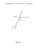
[0005] For example, a sensor unit is mounted on a sports equipment via an attachment in a swing analysis device. Various methods of mounting the sensor unit on the sports equipment have been used. For example, as illustrated in FIG. 24, in some cases, the sensor unit is mounted on a rear side of a golf club when viewed from a user's golf address position. However, acceleration acting in a swing direction tends to apply a strong force to the sensor unit in a direction opposite to the swing direction. Consequently, the attachment is rotated in a case of the above-described mounting direction, thereby causing a possibility that a position and a posture of the sensor unit may be misaligned. In this case, an error occurs in a measurement result of the sensor unit, thereby resulting in poor measurement accuracy. This disadvantage is more likely to occur as the sensor unit gets heavier, and occurs even when the sensor unit is mounted on the golf club without interposing the attachment therebetween. Without being limited to the golf club, this disadvantage may also commonly occur in a sports equipment for use in swinging.
SUMMARY
[0006] An advantage of some aspects of the invention is to provide a sensor unit and a sensor set which can be mounted on a sports equipment so as to reduce effects of acceleration acting in a swing direction. Another advantage of some aspects of the invention is to provide a sports equipment and a mounting method of a sensor unit, which can reduce the effects of acceleration acting on the sensor unit in the swing direction.
[0007] The invention can be implemented as the following forms or application examples.
APPLICATION EXAMPLE 1
[0008] A sensor unit according to this application example is mounted on a sports equipment so as to detect an inertial amount generated by a swing, in which a detection axis of the inertial amount generated along a direction orthogonal to a surface located on the sports equipment side when the sensor unit is mounted on the sports equipment is set to extend along a direction of the swing.
[0009] The "direction of the swing" means a direction in which the sensor unit moves during the swing. For example, the direction of the swing at any point of time during the swing may be a speed direction of the sensor unit at the point of time.
[0010] In the sensor unit according to this application example, the detection axis of the inertial amount generated along the direction orthogonal to the surface located on the sports equipment side when the sensor unit is mounted on the sports equipment is set to extend along the direction of the swing. Accordingly, an angle formed between the surface located on the sports equipment side and the swing direction when the sensor unit is mounted on the sports equipment in accordance with the above-described setting approximates to a right angle. Therefore, even when acceleration acting in the direction of the swing applies a strong force to the sensor unit according to the application example in a direction opposite to the swing direction, a force to rotate the sensor unit around an axis of the sports equipment is relatively weak. Thus, it is possible to reduce possibilities that a position or a posture of the sensor unit may be misaligned. In this manner, the sensor unit according to the application example can be mounted on the sports equipment so as to reduce effects of acceleration acting in the swing direction.
APPLICATION EXAMPLE 2
[0011] A sensor unit according to this application example is mounted on a sports equipment so as to detect an inertial amount generated by a swing, in which a surface located on the sports equipment side when the sensor unit is mounted on the sports equipment is set to be a surface orthogonal to a direction of the swing.
[0012] In the sensor unit according to this application example, the surface located on the sports equipment side when the sensor unit is mounted on the sports equipment is set to be the surface orthogonal to the direction of the swing. Accordingly, an angle formed between the surface located on the sports equipment side and the swing direction when the sensor unit is mounted on the sports equipment in accordance with the above-described setting approximates to a right angle. Therefore, even when acceleration acting in the direction of the swing applies a strong force to the sensor unit according to the application example in a direction opposite to the swing direction, a force to rotate the sensor unit around an axis of the sports equipment is relatively weak. Thus, it is possible to reduce possibilities that a position or a posture of the sensor unit may be misaligned. In this manner, the sensor unit according to the application example can be mounted on the sports equipment so as to reduce effects of acceleration acting in the swing direction.
APPLICATION EXAMPLE 3
[0013] A sensor unit according to this application example is mounted on a sports equipment so as to detect an inertial amount generated by a swing, in which a detection axis of the inertial amount generated along a direction orthogonal to a surface located on the sports equipment side when the sensor unit is mounted on the sports equipment is set to extend along a direction orthogonal to a hitting surface of the sports equipment.
[0014] In the sensor unit according to this application example, the detection axis of the inertial amount generated along the direction orthogonal to the surface located on the sports equipment side when the sensor unit is mounted on the sports equipment is set to extend along the direction orthogonal to the hitting surface of the sports equipment. Accordingly, the surface located on the sports equipment side and the hitting surface of the sports equipment when the sensor unit is mounted on the sports equipment in accordance with the above-described setting are approximately parallel to each other. That is, an angle formed between the surface located on the sports equipment side and the swing direction of the sensor unit approximates to a right angle. Therefore, even when acceleration acting in the swing direction applies a strong force to the sensor unit according to the application example in a direction opposite to the direction of the swing, a force to rotate the sensor unit around an axis of the sports equipment is relatively weak. Thus, it is possible to reduce possibilities that a position or a posture of the sensor unit may be misaligned. In this manner, the sensor unit according to the application example can be mounted on the sports equipment so as to reduce effects of acceleration acting in the swing direction.
APPLICATION EXAMPLE 4
[0015] A sensor set according to this application example includes the sensor unit according to any one of the application examples described above and a holding tool for mounting the sensor unit on the sports equipment.
[0016] In the sensor set according to this application example, a force which is generated by acceleration acting in the swing direction so as to rotate the holding tool around an axis of the sports equipment is relatively weak. Thus, it is possible to reduce possibilities that a position or a posture of the sensor unit may be misaligned. In this manner, the sensor set according to the application example can be mounted on the sports equipment so as to reduce effects of acceleration acting in the swing direction.
APPLICATION EXAMPLE 5
[0017] A sports equipment according to the application example is a sport equipment on which a sensor unit for detecting an inertial amount generated by a swing is mounted, in which a detection axis of the inertial amount generated along a direction orthogonal to a surface located on the sports equipment side extends along a direction of the swing in the sensor unit.
[0018] In the sports equipment according to this application example, the detection axis of the inertial amount generated along the direction orthogonal to the surface located on the sports equipment side extends along the direction of the swing in the sensor unit. Accordingly, an angle formed between the surface located on the sports equipment side and the swing direction approximates to a right angle. Therefore, even when acceleration acting in the swing direction applies a strong force to the sensor unit in a direction opposite to the swing direction, a force to rotate the sensor unit around an axis of the sports equipment is relatively weak. Thus, it is possible to reduce possibilities that a position or a posture of the sensor unit may be misaligned. In this manner, the sports equipment according to the application example can reduce the effects of acceleration acting on the sensor unit in the swing direction.
APPLICATION EXAMPLE 6
[0019] A sports equipment according to this application example is a sport equipment on which a sensor unit for detecting an inertial amount generated by a swing is mounted, in which a surface located on the sports equipment side is a surface orthogonal to a direction of the swing in the sensor unit.
[0020] In the sports equipment according to this application example, the surface located on the sports equipment side is the surface orthogonal to the direction of the swing in the sensor unit. Accordingly, an angle formed between the surface located on the sports equipment side and the swing direction approximates to a right angle. Therefore, even when acceleration acting in the swing direction applies a strong force to the sensor unit in a direction opposite to the swing direction, a force to rotate the sensor unit around an axis of the sports equipment is relatively weak. Thus, it is possible to reduce possibilities that a position or a posture of the sensor unit may be misaligned. In this manner, the sports equipment according to the application example can reduce the effects of acceleration acting on the sensor unit in the swing direction.
APPLICATION EXAMPLE 7
[0021] A sports equipment according to this application example is a sport equipment on which a sensor unit for detecting an inertial amount generated by a swing is mounted, and which includes a hitting surface. In the sensor unit, a detection axis of the inertial amount generated along a direction orthogonal to a surface located on the sports equipment side extends along a direction orthogonal to the hitting surface.
[0022] In the sports equipment according to this application example, the detection axis of the inertial amount generated along the direction orthogonal to the surface located on the sports equipment side extends along the direction orthogonal to the hitting surface of the sports equipment, in the sensor unit. Accordingly, the surface located on the sports equipment side and the hitting surface of the sports equipment are approximately parallel to each other. That is, an angle formed between the surface located on the sports equipment side and the swing direction of the sensor unit approximates to a right angle. Therefore, even when acceleration acting in the swing direction applies a strong force to the sensor unit in a direction opposite to the direction of the swing, a force to rotate the sensor unit around an axis of the sports equipment is relatively weak. Thus, it is possible to reduce possibilities that a position or a posture of the sensor unit may be misaligned. In this manner, the sports equipment according to the application example can reduce the effects of acceleration acting on the sensor unit in the swing direction.
APPLICATION EXAMPLE 8
[0023] The sports equipment according to the application example described above may further include a holding tool for mounting the sensor unit on the sports equipment.
[0024] In the sports equipment according to this application example, a force which is generated by acceleration acting in the swing direction so as to rotate the holding tool around an axis of the sports equipment is relatively weak. Thus, it is possible to reduce possibilities that a position or a posture of the sensor unit may be misaligned. In this manner, the sports equipment according to the application example can reduce the effects of acceleration acting on the sensor unit in the swing direction.
APPLICATION EXAMPLE 9
[0025] A mounting method of a sensor unit according to this application example is a mounting method in which a sensor unit for detecting an inertial amount generated by a swing is mounted on a sports equipment. The method includes preparing the sports equipment, preparing the sensor unit, and mounting the sensor unit on the sports equipment so that a detection axis of the inertial amount generated along a direction orthogonal to a surface located on the sports equipment side of the sensor unit extends along a direction of the swing.
[0026] In the mounting method of the sensor unit according to this application example, the sensor unit is mounted on the sports equipment so that the detection axis of the inertial amount generated along the direction orthogonal to the surface located on the sports equipment side of the sensor unit extends along the direction of the swing. Accordingly, an angle formed between the surface located on the sports equipment side of the mounted sensor unit and the swing direction approximates to a right angle. Therefore, even when acceleration acting in the swing direction applies a strong force to the sensor unit in a direction opposite to the swing direction, a force to rotate the sensor unit around an axis of the sports equipment is relatively weak. Thus, it is possible to reduce possibilities that a position or a posture of the sensor unit may be misaligned. In this manner, according to the mounting method of the sensor unit in the application example, it is possible to reduce the effects of acceleration acting on the sensor unit in the swing direction.
APPLICATION EXAMPLE 10
[0027] Amounting method of a sensor unit according to this application example is a mounting method in which a sensor unit for detecting an inertial amount generated by a swing is mounted on a sports equipment. The method includes preparing the sports equipment, preparing the sensor unit, and mounting the sensor unit on the sports equipment so that a surface located on the sports equipment side of the sensor unit is a surface orthogonal to a direction of the swing.
[0028] In the mounting method of the sensor unit according to this application example, the sensor unit is mounted on the sports equipment so that the surface located on the sports equipment side of the sensor unit is the surface orthogonal to the direction of the swing. Accordingly, an angle formed between the surface located on the sports equipment side of the mounted sensor unit and the swing direction approximates to a right angle. Therefore, even when acceleration acting in the swing direction applies a strong force to the sensor unit in a direction opposite to the swing direction, a force to rotate the sensor unit around an axis of the sports equipment is relatively weak. Thus, it is possible to reduce possibilities that a position or a posture of the sensor unit may be misaligned. In this manner, according to the mounting method of the sensor unit in the application example, it is possible to reduce the effects of acceleration acting on the sensor unit in the swing direction.
APPLICATION EXAMPLE 11
[0029] Amounting method of a sensor unit according to this application example is a mounting method in which a sensor unit for detecting an inertial amount generated by a swing is mounted on a sports equipment including a hitting surface. The method includes preparing the sports equipment, preparing the sensor unit, and mounting the sensor unit on the sports equipment so that a detection axis of the inertial amount generated along a direction orthogonal to a surface located on the sports equipment side of the sensor unit extends along a direction orthogonal to the hitting surface.
[0030] In the mounting method of the sensor unit according to this application example, the sensor unit is mounted on the sports equipment so that the detection axis of the inertial amount generated along the direction orthogonal to the surface located on the sports equipment side of the sensor unit extends along the direction orthogonal to the hitting surface of the sports equipment. Accordingly, the surface located on the sports equipment side of the mounted sensor unit and the hitting surface of the sports equipment are approximately parallel to each other. That is, an angle formed between the surface located on the sports equipment side of the mounted sensor unit and the swing direction approximates to a right angle. Therefore, even when acceleration acting in the swing direction applies a strong force to the sensor unit in a direction opposite to the direction of the swing, a force to rotate the sensor unit around an axis of the sports equipment is relatively weak. Thus, it is possible to reduce possibilities that a position or a posture of the sensor unit may be misaligned. In this manner, according to the mounting method of the sensor unit in the application example, it is possible to reduce the effects of acceleration acting on the sensor unit in the swing direction.
APPLICATION EXAMPLE 12
[0031] The mounting method of the sensor unit according to the application example described above may further include preparing a holding tool for mounting the sensor unit on the sport equipment, and mounting the holding tool on the sports equipment. In mounting the sensor unit on the sports equipment, the sensor unit may be mounted on the sports equipment by causing the holding tool mounted on the sports equipment to hold the sensor unit.
[0032] In the mounting method of the sensor unit according to this application example, a force which is generated by acceleration acting in the swing direction so as to rotate the mounted holding tool around an axis of the sports equipment is relatively weak. Thus, it is possible to reduce possibilities that a position or a posture of the sensor unit may be misaligned. In this manner, according to the mounting method of the sensor unit in the application example, it is possible to reduce the effects of acceleration acting on the sensor unit in the swing direction.
BRIEF DESCRIPTION OF THE DRAWINGS
[0033] The invention will be described with reference to the accompanying drawings, wherein like numbers reference like elements.
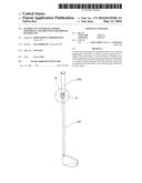
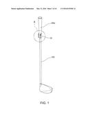
[0034] FIG. 1 is an external perspective view illustrating a state where a holding tool according to the present embodiment is mounted on a sports equipment (golf club).
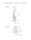
[0035] FIG. 2 is an enlarged view illustrating a range indicated by A in FIG. 1, and is a schematic view illustrating a process where a sensor unit is fitted to the holding tool according to the embodiment.
[0036] FIG. 3 is an enlarged view illustrating the range indicated by A in FIG. 1, and is a schematic view illustrating a sensor-installed sports equipment in a state where the holding tool according to the embodiment has been mounted on the sports equipment and the sensor unit has been fitted to the holding tool.
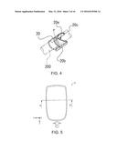
[0037] FIG. 4 is a perspective view of the holding tool according to the embodiment, and is a perspective view when viewed in a direction of an arrow indicated by J in FIG. 11.
[0038] FIG. 5 is a schematic view when the sensor unit according to the embodiment is planarly viewed from an upper surface thereof.
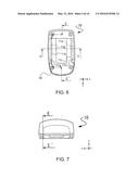
[0039] FIG. 6 is a schematic view when the sensor unit according to the embodiment is planarly viewed from a lower surface thereof.
[0040] FIG. 7 is a schematic view when the sensor unit according to the embodiment is viewed in a direction of an arrow indicated by F in FIG. 5.
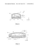
[0041] FIG. 8 is a schematic view illustrating a cross section in which the sensor unit according to the embodiment is cut away along line B-B' in FIGS. 5 and 6.
[0042] FIG. 9 is a schematic view illustrating a cross section in which the sensor unit according to the embodiment is cut away along line C-C' in FIG. 6 and line E-E' in FIG. 7.
[0043] FIG. 10 is a schematic view when the holding tool according to the embodiment is planarly viewed from a mounting surface side thereof.
[0044] FIG. 11 is a schematic view when the holding tool according to the embodiment is viewed in a direction of an arrow indicated by G in FIG. 10.
[0045] FIG. 12 is a schematic view when the holding tool according to the embodiment is viewed in a direction of an arrow indicated by H in FIG. 10.
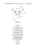
[0046] FIG. 13 is a flowchart illustrating a mounting method of the sensor unit according to the embodiment.
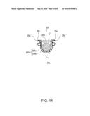
[0047] FIG. 14 is a schematic view illustrating a cross section in a state where the holding tool according to the embodiment is mounted on the sports equipment (golf club).
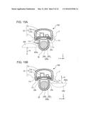
[0048] FIGS. 15A and 15B are schematic views illustrating each cross section in a state where the sensor unit and the holding tool are mounted on the golf club by using a mounting method according to the embodiment.
[0049] FIG. 16 is an enlarged view illustrating a range indicated by J in FIGS. 15A and 15B.
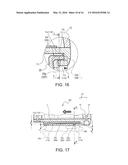
[0050] FIG. 17 is a schematic view illustrating a cross section taken along line L-L' in FIG. 16.
[0051] FIG. 18 is a schematic view illustrating a cross section taken along line M-M' in FIG. 17.
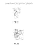
[0052] FIG. 19 is a schematically enlarged view illustrating an operation state of a pressing projection.
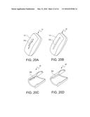
[0053] FIGS. 20A to 20D are schematic views illustrating some examples of an external shape of a direction indicator in the sensor unit.
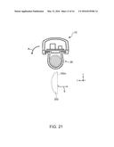
[0054] FIG. 21 is a schematic view illustrating a cross section in a state where a sensor unit and a holding tool are mounted on a golf club by using a mounting method in the related art.
[0055] FIG. 22 is an external view illustrating the sports equipment and a motion analysis device according to the embodiment.
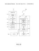
[0056] FIG. 23 is a block diagram illustrating the motion analysis device according to the embodiment.
[0057] FIG. 24 is a view for describing a mounting method of a sensor unit in the related art.
DESCRIPTION OF EXEMPLARY EMBODIMENTS
[0058] Hereinafter, some embodiments according to the invention will be described. The embodiments described below are intended to describe an example of the invention. Without being limited to the following embodiments at all, the invention includes various modification examples which are embodied within the scope not changing the gist of the invention. All configurations described below are not necessarily indispensable configurations of the invention.
1. Sensor Set
[0059] A sensor set according to the embodiment includes a holding tool and a sensor unit. The holding tool according to the embodiment is mounted on a sports equipment so as to clasp the sports equipment. The holding tool is a tool or an attachment for mounting the sensor unit (to be described later) on the sports equipment. In the description herein, the meaning of "the holding tool clasps the sports equipment" indicates that the holding tool is mounted on and fixed to (held by) the sports equipment having a rod shape, a columnar shape, or a cylindrical shape so as to clasp (grasp, clutch, or grip) the sports equipment. The meaning may indicate a state where the holding tool is fixed to (held by) the sports equipment by covering at least a half peripheral portion of the sports equipment without covering the entire periphery. In other words, this aspect can be described by the meanings of "the holding tool seizes the sports equipment" and "the holding tool is attached to the sports equipment by seizing the sports equipment".
1.1. Sports Equipment
[0060] The sports equipment on which the holding tool and the sensor unit are mounted will be described. For example, the sports equipment on which the holding tool according to the embodiment is mounted has a clasp-available shape such as a rod shape, a columnar shape, and a cylindrical shape. As long as the sports equipment performs swinging movement independently or passively, the shape is not limited thereto. For example, the swinging movement may be accompanied by spatial position movement, a change in shapes or postures, rotations, and vibrations. This sports equipment includes equipment used in various athletic sports, for example, golf clubs, baseball bats, tennis racquets, and bamboo swords for Kendo.
[0061] Hereinafter, a case where the sports equipment is the golf club will be described. Although no particular limitation is imposed on the golf club, a case where a shaft of the golf club has a rubber grip attached thereto will be described. In this description, an aspect will be described in which the holding tool according to the embodiment clasps a portion of the rubber grip. However, the shaft may be clasped, or a boundary portion therebetween may be clasped.
1.2. Holding Tool
[0062] A holding tool 20 according to the embodiment has a curved plate shape, and clasps a rod-shaped golf club 200 (sports equipment). For example, the holding tool 20 may be configured to include a mechanism for fixing a sensor unit 10.
[0063] FIG. 1 is an external perspective view illustrating a state where the holding tool 20 according to the embodiment is mounted on the golf club 200. FIG. 2 is an enlarged view illustrating a range indicated by A in FIG. 1, and is a schematic view illustrating a process where the sensor unit 10 is fitted to the holding tool 20 according to the embodiment. FIG. 3 is an enlarged view illustrating the range indicated by A in FIG. 1, and is a schematic view illustrating a state where the sensor unit 10 has been fitted to the holding tool 20 according to the embodiment.
[0064] As illustrated in FIG. 1, the sensor unit 10 internally including a sensor portion 13 (not illustrated) is mounted on the holding tool 20 which can be mounted on a grip portion 200a of the golf club 200 via fitting portions 20b and 20c in a direction of an arrow illustrated in FIG. 2. As illustrated in FIG. 3, the sensor unit 10 is mounted on the golf club 200.
[0065] As illustrated in FIG. 3, a sensor set 100 (including the holding tool 20 and the sensor unit 10 fitted to the holding tool 20) according to the embodiment is mounted on the golf club 200 serving as the sports equipment. That is, when the holding tool 20 is mounted on the golf club 200 and the fitting portions 20b and 20c are fitted to the sensor unit 10, the sensor unit 10 is mounted on the golf club 200 so as to surround the golf club 200.
[0066] A material of the holding tool 20 is not particularly limited as long as a biasing force for clasping the golf club 200 can be obtained. For example, if polyethylene, polypropylene, polystyrene, polyvinyl chloride, polycarbonate, ABS resin, fluororesin, acrylic resin, or synthetic resin such as a copolymer of these materials is used, the material can contribute to weight reduction of the holding tool 20.
[0067] FIG. 4 is a perspective view of the holding tool 20 (referring to FIG. 11, the viewing direction is a direction of an arrow indicated by J). As illustrated in FIG. 4, the holding tool 20 may have the fitting portions 20b and 20c on a distal end side for use in clasping the golf club 200. The distal end side for use in clasping the golf club 200 is a portion where the golf club 200 is first gripped when the holding tool 20 clasps the golf club 200. A cutting plane P cut away by a plane orthogonal to an extending direction (longitudinal direction of the shaft) of the golf club 200 can be referred to as an end portion side of the holding tool 20.
[0068] For example, the fitting portions 20b and 20c have a function for being fitted to the sensor unit 10 (to be described later). These fitting portions 20b and 20c enable the sensor unit 10 to be stably mounted on the golf club 200 in such a way that dropping, misalignment, or rotating of the sensor unit 10 is less likely to occur.
[0069] The fitting portions 20b and 20c will be described in detail later. When the holding tool 20 is mounted on the golf club 200 and the fitting portions 20b and 20c are fitted to the sensor unit 10, the sensor unit 10 and the holding tool 20 (sensor set 100) are mounted on the golf club 200 so as to surround the golf club 200. Furthermore, when the fitting portions 20b and 20c are fitted to the sensor unit 10, a degree of biasing the golf club 200 may be heightened. According to this configuration, the sensor unit 10 can be more stably mounted on the golf club 200 in such a way that dropping, misalignment, or rotating of the sensor unit 10 is less likely to occur.
[0070] The embodiment adopts an aspect in which the fitting portions 20b and 20c have a rail shape and are inserted into grooves (grooves 11d and 11e in FIG. 6 (to be described later)) belonging to the sensor unit 10 so as to be slidingly fitted to the sensor unit 10. However, the aspect is not particularly limited as long as the sensor unit 10 can be fixed to the golf club 200.
1.3. Sensor Unit
[0071] Referring to FIGS. 5 to 9, the sensor unit 10 will be described. FIG. 5 is a schematic view when the sensor unit is planarly viewed from an upper surface, and FIG. 6 is a schematic view when the sensor unit is planarly viewed from a lower surface. FIG. 7 is a schematic view when the sensor unit is viewed in a direction of an arrow indicated by F in FIG. 5, and FIG. 8 is a schematic view illustrating a cross section in which the sensor unit is cut away along line B-B' in FIGS. 5 and 6. FIG. 9 is a schematic view illustrating a cross section in which the sensor unit is cut away along line C-C' in FIG. 6 and line E-E' in FIG. 7.
[0072] The sensor unit 10 is mounted on the golf club 200, and detects an inertial amount (for example, angular speed or acceleration) generated by a swing. According to the embodiment, in the sensor unit 10, three detection axes (X-axis, Y-axis, and Z-axis) which are orthogonal to each other are defined. In FIGS. 5 to 9, respective directions of the three detection axes (X-axis, Y-axis, and Z-axis) of the sensor unit 10 are also illustrated.
[0073] As illustrated in FIGS. 8 and 9, the sensor unit 10 configures a housing in which an internal space 10a is formed by a cover 12 fixed to a base 11 by a screw 14. On a surface 11a on the internal space 10a side of the base 11, a circuit board 13a which is the sensor portion 13 serving as a detector of the sensor unit 10 configured to include an electronic device 13b and the circuit board 13a having the electronic device 13b mounted thereon is fixedly attached to the surface 11a of the base 11 by means of adhesion. At least one electronic device 13b includes an inertial sensor such as a three-axis acceleration sensor and a three-axis angular speed sensor.
[0074] The three detection axes (X-axis, Y-axis, and Z-axis) of the inertial sensor may be respectively coincident with the three detection axes (X-axis, Y-axis, and Z-axis) defined for the sensor unit 10. Alternatively, the sensor unit 10 may store correction parameters corresponding to previously calculated errors of the detection axes, and may output an inertial amount of the X-axis, the Y-axis, and the Z-axis by using the correction parameters and correcting an error amount of a detection value of the inertial sensor. The sensor unit 10 may not perform correction calculation, and may output data relating to the inertial amount of the X-axis, the Y-axis, and the Z-axis, which includes the errors. An external device (motion analysis device) which receives the data may perform the correction calculation.
[0075] Means for fixing the cover 12 to the base 11 is not limited to the screw 14. For example, adhesion may be used, and fixing by means of welding can also be used if the base 11 and the cover 12 are formed of a plastic material.
[0076] As illustrated in FIGS. 6 and 7, in the base 11, projections 11b and 11c extend in parallel with each other along a direction of the Y-axis. A groove 11d serving as a recessed portion is formed in the projection 11b along the direction of the Y-axis, and a groove 11e serving as a recessed portion is also formed in the projection 11c along the direction of the Y-axis. As illustrated in FIG. 8, openings of the groove 11d and the groove 11e in a direction of the X-axis are formed so as to face each other. As illustrated in FIG. 9, a side of the groove 11d and the groove 11e in the direction of the Y-axis (+), that is, a side in an incorporating direction of the sensor unit 10 illustrated in FIG. 2 is open, and a groove wall 11f is formed in the opposite direction. As illustrated in FIGS. 6 and 9, a cutout portion 11g is formed in the projection 11b serving as an engagement portion for engaging with a disengagement preventing projection of the holding tool 20, and a cutout portion 11h is formed in the projection 11c.
[0077] According to the embodiment, in the sensor unit 10, the detection axis of the inertial amount generated along a direction orthogonal to a surface located on the golf club 200 side when the sensor unit 10 is mounted on the golf club 200 may be set to extend along a direction of a swing. Alternatively, a surface located on the golf club 200 side when the sensor unit 10 is mounted on the golf club 200 may be set to be a surface orthogonal to the direction of the swing. Alternatively, in the sensor unit 10, the detection axis of the inertial amount generated along the direction orthogonal to the surface located on the golf club 200 side when the sensor unit 10 is mounted on the golf club 200 may be set to extend along a direction orthogonal to a hitting surface (face of a head) of the golf club 200. Alternatively, in the sensor unit 10, the detection axis of the inertial amount generated along the direction orthogonal to the surface located on the golf club 200 side in a state before a user starts a swing (state at a golf address position) when the sensor unit 10 is mounted on the golf club 200 may be set to extend along a ball target direction.
[0078] According to the embodiment, when the sensor unit 10 is mounted on the golf club 200, a lower surface (bottom surface) of the sensor unit 10 which faces the golf club 200 is the surface located on the golf club 200 side. Therefore, according to the embodiment, in the sensor unit 10, the Z-axis extending along a direction orthogonal to the lower surface (bottom surface) among the three detection axes (X-axis, Y-axis, and Z-axis) which are orthogonal to each other may be set to extend along the direction of the swing (to be most approximate to the swing direction). Alternatively, in the sensor unit 10, the lower surface (bottom surface) may be set to be the surface orthogonal to the direction of the swing. Alternatively, in the sensor unit 10, the lower surface (bottom surface) may be set to extend along a direction orthogonal to the face of the golf club 200. Alternatively, in the sensor unit 10, the Z-axis extending along the direction orthogonal to the lower surface (bottom surface) may be set to extend along the ball target direction (to be most approximate to the ball target direction) at the user's golf address position.
[0079] For example, the meaning of "being set" may indicate that a predetermined detection axis of the sensor unit 10 is determined in advance to extend along a predetermined direction (for example, the Z-axis extends in the direction of the swing), or may indicate that a direction in which the sensor unit 10 is mounted on the golf club 200 is determined in advance. For example, an instruction manual of the sensor unit 10 may instruct how to mount the sensor unit 10 so that the Z-axis becomes parallel to the direction of the swing or so that the lower surface (bottom surface) becomes parallel to the face of the golf club 200.
1.4. Fitting and Assembling
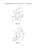
[0080] FIGS. 10 to 12 illustrate the holding tool 20. FIG. 10 is a plan view of the holding tool 20, FIG. 11 is a side view when the holding tool 20 is viewed in a direction of an arrow indicated by G in FIG. 10, and FIG. 12 is a side view when the holding tool 20 is viewed in a direction of an arrow indicated by H in FIG. 10. FIGS. 10 to 12 also illustrate respective directions of the three detection axes (X-axis, Y-axis, and Z-axis) of the sensor unit 10 when the sensor unit 10 is mounted on the holding tool 20.
[0081] As illustrated in FIG. 12, the holding tool 20 includes a mounting surface 20a to be mounted on the golf club 200 so as to be wound therearound, a fitting portion 20b serving as a projection-shaped portion which is inserted into the groove 11d of the sensor unit 10 illustrated in FIG. 2, which projects in the direction of the X-axis (-), and which extends in the direction of the Y-axis, and a fitting portion 20c serving as a projection-shaped portion which is inserted into the groove 11e, which projects in the direction of the X-axis (+), and which extends in the direction of the Y-axis.
[0082] As illustrated in FIG. 11, one end portion 20d of the holding tool 20 in the direction of the ±Y-axis is formed so as to extend along a plane X-Z, but the other end portion 20e intersects a plane X-Z. In this example, the other end portion 20e is formed in a shape extending along a columnar plane Co. As a result, as illustrated in FIG. 10, a planar shape of the other end portion 20e is a concave shape. Since the other end portion 20e is formed in this way, one end portion 20d is allowed to have a clearly different shape. Therefore, for example, when the sensor unit 10 to be fitted to the holding tool 20 has a function by which the incorporating direction is designated, the holding tool 20 is mounted on the golf club 200 after aligning the other end portion 20e having a different shape with the golf club 200 as an indicator to indicate the incorporating direction. In this manner, it is possible to prevent the sensor unit 10 from being erroneously mounted thereon in the incorporating direction. The embodiment is not limited to a case where the other end portion 20e is allowed to have a shape which is different from that of one end portion 20d. The other end portion 20e may be provided with a simple marking.
[0083] The holding tool 20 may include disengagement preventing projections 20f and 20g of the sensor unit 10. The disengagement preventing projections 20f and 20g engage with an engagement portion (not illustrated) of the sensor unit 10 when the sensor unit 10 is incorporated therein (to be described later), thereby preventing the sensor unit 10 from disengaging from the holding tool 20. Since the disengagement preventing projections 20f and 20g are provided, there may be provided pressing projections 20h and 20j for disengaging the disengagement preventing projections 20f and 20g from the engagement portion of the sensor unit 10 when the sensor unit 10 is detached from the holding tool 20. When the sensor unit is detached from the holding tool 20, the pressing projections 20h and 20j are pressed by a finger 300 in an arrow direction as illustrated in FIG. 12, and a distance between the disengagement preventing projections 20f and 20g is shortened. Then, the sensor unit 10 can be detached from the holding tool 20 by disengaging the disengagement preventing projections 20f and 20g from the engagement portion of the sensor unit 10.
1.5. Mounting Method of Sensor Unit
[0084] Next, a method of mounting the sensor unit 10 on the golf club 200 will be described with reference to a flowchart in FIG. 13. As illustrated in FIG. 13, a user first prepares the golf club 200, the sensor unit 10, and the holding tool 20 (S10, S20, and S30). Next, the user mounts the holding tool 20 on the golf club 200 (S40).
[0085] Next, the user mounts the sensor unit 10 on the golf club 200 by causing the holding tool 20 mounted on the golf club 200 to hold the sensor unit 10 (S50). In this step S50, the user may mount the sensor unit 10 on the golf club 200 so that the Z-axis of the sensor unit 10 extends along the direction of the swing. Alternatively, the user may mount the sensor unit 10 on the golf club 200 so that the lower surface (bottom surface) of the sensor unit 10 becomes a surface orthogonal to the direction of the swing. Alternatively, the user may mount the sensor unit 10 on the golf club 200 so that the Z-axis of the sensor unit 10 extends along a direction orthogonal to the face of the golf club 200. Alternatively, the user may mount the sensor unit 10 on the golf club 200 so that the Z-axis of the sensor unit 10 extends along the ball target direction at the user's golf address position.
[0086] FIG. 14 is a sectional view for describing a state where the holding tool 20 is mounted on the golf club 200. As illustrated in FIG. 14, the holding tool 20 is mounted on the grip portion 200a of the golf club 200. The grip portion 200a has a configuration in which a grip rubber 200c for preventing slip is applied to or wound around a shaft portion 200b. For example, the grip rubber 200c is formed of an elastic material such as rubber and urethane elastomer. A repulsive force generated by the mounting surface 20a (inner surface of the holding tool 20) of the holding tool 20 compressing a portion between the grip rubber 200c and the shaft portion increases a frictional force between the holding tool 20 and the grip rubber 200c. In this manner, the holding tool 20 can become less likely to be misaligned with the golf club 200.
[0087] In the embodiment, a form in which the holding tool 20 is mounted on the golf club 200 has been described as an example. However, for example, when the grip portion does not include means for preventing slip as in a baseball bat, an elastic member like the grip rubber 200c illustrated in FIG. 14 may be interposed between the baseball bat and the mounting surface 20a of the holding tool 20. A member for preventing slip which serves as a so-called interposed member may be arranged therein. As a material of the interposed member, it is preferable to use an elastic resin such as rubber and urethane elastomer, or soft metal.
[0088] FIGS. 15A and 15B are sectional views taken at a position corresponding to line B-B' illustrated in FIGS. 5 and 6, in a state where the holding tool 20 and the sensor unit 10 are mounted on the golf club 200 by using the mounting method according to the embodiment. FIGS. 15A and 15B also illustrate respective directions of the three axes (X-axis, Y-axis, and Z-axis) of the sensor unit 10. In FIGS. 15A and 15B, a head 202 of the golf club 200 is also illustrated by a dashed line in order to facilitate subsequent description. Except for a position and orientation of the head 202, both drawings are the same as each other. The sensor unit 10 is moved to the holding tool 20 mounted on the golf club 200 as illustrated in FIG. 2, in the arrow direction. As illustrated in FIG. 15A or 15B, the fitting portion 20b and the fitting portion 20c which are included in the holding tool 20 are inserted into the groove 11d and the groove 11e which are formed in the sensor unit 10. Specifically, the fitting portions 20b and 20c are slidingly inserted into the grooves 11d and 11e. In this manner, the sensor unit 10 is mounted on the holding tool 20 mounted on the golf club 200.
[0089] As illustrated in FIG. 14, if the holding tool 20 is mounted on the grip portion 200a of the golf club 200, the grip rubber 200c of the grip portion 200a is interposed between the mounting surface 20a of the holding tool 20 and the shaft portion 200b. In this state, due to the elasticity of the grip rubber 200c, a mounting opening 20k facing the mounting surface 20a is displaced and widened. The fitting portion 20b and the fitting portion 20c are brought into a state of a fitting portion 20b' and a fitting portion 20c' which are moved outward.
[0090] As illustrated in FIG. 15A or 15B, the fitting portion 20b and the fitting portion 20c in the state of the fitting portion 20b' and the fitting portion 20c' are inserted into the groove 11d and the groove 11e, positions thereof are corrected in a direction of an illustrated arrow K by a groove wall surface 11j of the groove 11e and a groove wall surface 11k of the groove 11e as illustrated in FIG. 16. That is, in the state illustrated in FIG. 15A or 15B, the position of the holding tool 20 is corrected in a direction in which the grip rubber 200c is compressed. In this manner, the holding tool 20 can improve a holding force for holding the grip portion 200a. Therefore, the sensor set 100 (sensor unit 10 and holding tool 20) can be reliably aligned with the golf club 200, and thus the sensor unit 10 is less likely to be misaligned even when an inertial force or an impact force is applied to the sensor set 100 by a swing of the golf club 200. Accordingly, proper swing data of the golf club 200 can be obtained.
[0091] As illustrated in FIGS. 15A and 15B, according to the embodiment, the Y-axis of the sensor unit 10 extends along the longitudinal direction of the shaft portion 200b of the golf club 200 in a state where the sensor unit 10 is mounted on the holding tool 20 mounted on the golf club 200. The X-axis of the sensor unit 10 extends along the direction orthogonal to a direction S of a swing.
[0092] Furthermore, the Z-axis of the sensor unit 10 extends along the direction S of the swing. In other words, the lower surface (bottom surface) of the sensor unit 10 is the surface orthogonal to the direction S of the swing, or the Z-axis of the sensor unit 10 extends along the direction S orthogonal to the face 202a of the head 202 of the golf club 200. Therefore, due to acceleration acting in the swing direction, a strong force is applied to the sensor unit 10 in a direction opposite to the swing direction so that the sensor unit 10 moves away from the golf club 200 in a case of FIG. 15A, and so that the sensor unit 10 moves close to the golf club 200 in a case of FIG. 15B. However, in any case, a force to rotate the sensor unit 10 and the holding tool 20 is weak. Thus, even when swing speed is fast or even when swinging is repeatedly performed, the position or the posture of the sensor unit 10 is less likely to be misaligned. Accordingly, proper swing data of the golf club 200 can be obtained.
[0093] FIG. 17 is a schematic sectional view taken along line L-L' in FIG. 16. As illustrated in FIG. 17, the sensor unit 10 is moved to the holding tool 20 in a direction of an illustrated arrow, and the fitting portion 20c of the holding tool 20 is relatively inserted into the groove 11e. Similarly, the fitting portion 20b of the holding tool 20 is relatively inserted into the groove 11d. The groove 11e and the fitting portion 20c correspond to the line L-L' in FIG. 16. Accordingly, hereinafter, the groove 11e and the fitting portion 20c will be described as an example. The following description is similarly applied to the groove 11d and the fitting portion 20b.
[0094] When the sensor unit 10 is inserted into the holding tool 20 in the direction of the illustrated arrow, first, an end portion of the fitting portion 20c located on one end portion 20d side of the holding tool 20 starts to be inserted into the groove 11e. The fitting portion 20c is formed so that a thickness (direction of the Z-axis) t2 on one end portion 20d side and a height s of the groove 11e in the direction of the Z-axis satisfy t2<s. That is, the thickness of the fitting portion 20c on one end portion 20d side of the holding tool 20 is smaller than the groove height of the groove 11e. In this manner, the fitting portions can be easily incorporated therein when the insertion starts.
[0095] Furthermore, the fitting portion 20c is relatively inserted into the groove 11e, and as illustrated in FIG. 17, the disengagement preventing projection 20g of the holding tool 20 is fitted to the cutout portion 11h formed in the projection 11c, thereby completing the insertion. In this state, if a thickness t1 of the fitting portion 20c on the other end portion 20e side of the holding tool 20 is formed so as to satisfy a relationship of t1>t2, a gap between the groove 11e and the fitting portion 20c in the direction of the Z-axis is further narrowed on the other end portion 20e side, compared to one end portion 20d side in the holding tool 20. For example, under a condition of t1≈s or t1>s, the fitting portion 20c is brought into a state of being interposed between the surfaces of the groove 11e in the direction of the Z-axis. Accordingly, it is possible to prevent the sensor unit 10 from falling down from the holding tool 20. Since a backlash against the holding tool 20 in the direction of the Z-axis is suppressed for the sensor unit 10, proper swing data of the golf club 200 can be obtained.
[0096] FIG. 18 is a schematically enlarged sectional view taken along line M-M' in FIG. 17. As illustrated in FIG. 18, in a state where the fitting portion 20c is inserted into the groove 11e, the disengagement preventing projection 20g engages with the cutout portion 11h of the projection 11c by an engagement amount δ provided therebetween. This maintains a mounting state between the sensor unit 10 and the holding tool 20 as illustrated in FIG. 17.
[0097] When the sensor unit 10 is detached from the holding tool 20 in this state, as illustrated in FIG. 19, the pressing projection 20j is pressed in a direction of an illustrated arrow by the finger 300, for example. In this manner, the disengagement preventing projection 20g is separated from the cutout portion 11h, and in a state where a gap ε (ε>0) is generated, the sensor unit 10 is slid in a direction opposite to an arrow illustrated in FIG. 17, thereby enabling the sensor unit 10 to be detached from the holding tool 20. As described above, the disengagement preventing projections 20g and 20f, and the cutout portions 11h and 11g to which the disengagement preventing projections 20g and 20f can be fitted are provided therein. Accordingly, while capability of mounting the sensor unit 10 on the holding tool 20 is ensured, the sensor unit 10 can be easily detached from the holding tool 20 when necessary.
[0098] According to the embodiment, a user mounts the sensor unit 10 on the golf club 200 so that the Z-axis of the sensor unit 10 extends along the direction of the swing, in other words, so that the lower surface (bottom surface) of the sensor unit 10 is the surface orthogonal to the direction of the swing, or alternatively, so that the Z-axis of the sensor unit 10 extends along the direction orthogonal to the face of the golf club 200. Therefore, as means for clearly indicating a direction of at least one detection axis of the sensor unit 10, a detection device may be provided with a direction indicator of the detection axis as illustrated in FIGS. 20A to 20D. Any one of the direction indicators illustrated in FIGS. 20A to 20D indicates the direction of the Y-axis.
[0099] A form in which any one of direction indicators 12a, 12b, 20m, and 20n illustrated in FIGS. 20A to 20D having a projection shape is formed integrally with the cover 12 or the holding tool 20 is described as an example. However, without being limited thereto, both of them may have a concave shape formed by means of molding or engraving. A printed mark may also be employed. Without being limited to an arrow shape or a linear shape, any shape mark may be employed as long as directionality can be identified.
[0100] As another modification example, for example, if the detection axis of the sensor unit 10 is set in an extending direction of the groove portion and the fitting portion without disposing the direction indicator, the detection axis can be coincident with a predetermined direction by simply operating the base and the holding tool so as to be fitted to each other. Accordingly, it is possible to perform accurate motion detection.
[0101] As described above, the sensor unit 10 can be easily mounted on the holding tool 20 mounted on the golf club 200, by simply and slidingly fitting the sensor unit 10 to the holding tool 20 so that the rail-shaped fitting portions 20b and 20c included in the holding tool 20 are respectively inserted into the grooves 11d and 11e included in the sensor unit 10.
[0102] Furthermore, since the sensor unit 10 is mounted on the holding tool 20, the grip rubber 200c included in the grip portion 200a is compressed and interposed between the mounting surface 20a of the holding tool 20 and the shaft portion 200b, thereby allowing the sensor unit 10 to have an improved holding force for holding the golf club 200. In this manner, a mounting position can be prevented from being misaligned due to an inertial force or an impact force which is applied to the sensor set 100 by a swing of the golf club 200. Therefore, proper swing data of the golf club 200 can be obtained.
[0103] In addition to the slidingly fitted structure, a method may be employed in which the base and the holding tool are pressed against and fitted to each other by using a structure where a recessed portion such as a groove portion or a hole portion is disposed in any one of the base and the holding tool, and where a projection-shaped portion such as the projection is disposed in the other one of the base and the holding tool.
1.6. Operation Effect
[0104] By comparing with a case where the sensor unit 10 is mounted on the golf club 200 by using the mounting method in the related art, an operation effect of the mounting method of the sensor set 100 and the sensor unit 10 according to the embodiment will be described. FIG. 21 is a sectional view taken at a position corresponding to line B-B' illustrated in FIGS. 5 and 6, in a state where the holding tool 20 and the sensor unit 10 are mounted on the golf club 200 by using the mounting method in the related art. FIG. 21 also illustrates respective directions of the three axes (X-axis, Y-axis, and Z-axis) of the sensor unit 10. In FIG. 21, the head 202 of the golf club 200 is also illustrated by a dashed line. As illustrated in FIG. 21, according to the related art, the sensor unit 10 is set so that the Z-axis serving as the detection axis of the inertial amount generated along the direction orthogonal to the lower surface (bottom surface) located on the golf club 200 side when the sensor unit 10 is mounted on the golf club 200 is orthogonal to the direction S of the swing. Therefore, if the sensor unit 10 and the holding tool 20 are mounted on the golf club 200 in accordance with the setting in the related art, the lower surface (bottom surface) of the sensor unit 10 and the swing direction S are approximately parallel to each other. For this reason, if acceleration acting in the swing direction applies a strong force to the sensor unit 10 in a direction opposite to the swing direction, a force increases so as to rotate the sensor unit 10 and the holding tool 20 around the axis of the golf club 200 in a direction of an arrow R. Consequently, the position or the posture of the sensor unit 10 is likely to be misaligned.
[0105] In contrast, in the sensor set 100 according to the embodiment, the sensor unit 10 is set so that the Z-axis serving as the detection axis of the inertial amount generated along the direction orthogonal to the lower surface (bottom surface) located on the golf club 200 side when the sensor unit 10 is mounted on the golf club 200 extends along the direction of the swing. In other words, the sensor unit 10 is set so that the lower surface (bottom surface) located on the golf club 200 side when the sensor unit 10 is mounted on the golf club 200 is the surface orthogonal to the direction of the swing, or alternatively so that the Z-axis serving as the detection axis of the inertial amount generated along the direction orthogonal to the lower surface (bottom surface) located on the golf club 200 side when the sensor unit 10 is mounted on the golf club 200 extends along the direction orthogonal to the face 202a of the golf club 200. Therefore, when the sensor set 100 (sensor unit 10 and holding tool 20) according to the embodiment is mounted on the golf club 200 in accordance with any one of the above-described settings, an angle formed between the lower surface (bottom surface) of the sensor unit 10 and the swing direction approximates to a right angle.
[0106] Specifically, as described in the mounting method of the sensor unit 10 according to the embodiment, the sensor unit 10 and the holding tool 20 are mounted on the golf club 200 so that the Z-axis of the sensor unit 10 extends along the direction of the swing, in other words, so that the lower surface (bottom surface) of the sensor unit 10 is the surface orthogonal to the direction of the swing, or alternatively, so that the Z-axis of the sensor unit 10 extends along the direction orthogonal to the face 202a of the golf club 200. In this manner, an angle formed between the lower surface (bottom surface) of the mounted sensor unit 10 and the swing direction approximates to a right angle. Therefore, even when acceleration acting in the swing direction applies a strong force to the sensor unit 10 in a direction opposite to the swing direction, a force to rotate the sensor unit 10 and the holding tool 20 around the axis of the golf club 200 is relatively weak. Thus, it is possible to reduce possibilities that the position or the posture of the sensor unit 10 may be misaligned. In this manner, in the sensor set 100 according to the embodiment, the sensor unit 10 can be mounted on the golf club 200 so as to reduce the effects of acceleration acting in the swing direction. According to the mounting method of the sensor unit 10 in the embodiment, it is possible to reduce the effects of the acceleration acting on the sensor unit 10 in the swing direction.
[0107] As described above, according to the sensor set 100 in the embodiment or according to the mounting method of the sensor unit 10 in the embodiment, even when swing speed is fast or even when swinging is repeatedly performed, the position or the posture of the sensor unit 10 is less likely to be misaligned. Accordingly, proper swing data of the golf club 200 can be obtained.
2. Sensor-Installed Sports Equipment
[0108] A sensor-installed sports equipment 400 according to the embodiment is a sports equipment such as the golf club 200. For example, the above-described sensor set 100 (sensor unit 10 and holding tool 20) is mounted thereon (refer to FIGS. 3 and 22).
[0109] In particular, in the sports equipment 400 according to the embodiment, the sensor unit 10 is set so that the detection axis of the inertial amount generated along the direction orthogonal to the surface located on the golf club 200 side extends along the direction of the swing. In other words, the sensor unit 10 is set so that the surface located on the golf club 200 side is the surface orthogonal to the direction of the swing, or alternatively so that the detection axis of the inertial amount generated along the direction orthogonal to the surface located on the golf club 200 side extends along the direction orthogonal to the hitting surface (face of the head) of the golf club 200. This sports equipment 400 can be realized in such a way that the sensor unit 10 and the holding tool 20 in which the Z-axis is set to extend the direction of the swing are mounted on the golf club 200 by using the above-described mounting method.
[0110] According to this sports equipment 400, an angle formed between the surface (lower surface (bottom surface)) of the sensor unit 10 which is located on the golf club 200 side and the swing direction approximates to a right angle. Therefore, even when acceleration acting in the swing direction applies a strong force to the sensor unit 10 in the direction opposite to the swing direction, a force to rotate the sensor unit 10 and the holding tool 20 around the axis of the golf club 200 is relatively weak. Thus, it is possible to reduce possibilities that the position or the posture of the sensor unit 10 may be misaligned. In this manner, in the sports equipment 400 according to the embodiment, it is possible to reduce the effects of the acceleration acting on the sensor unit 10 in the swing direction.
[0111] Therefore, according to the sports equipment 400 in the embodiment, even when swing speed is fast or even when swinging is repeatedly performed, the position or the posture of the sensor unit 10 is less likely to be misaligned. Accordingly, proper swing data of the golf club 200 can be obtained.
3. Motion Analysis Device
[0112] FIG. 22 is an external view illustrating a motion analysis device according to the embodiment. As illustrated in FIG. 22, a motion analysis device 1000 according to the embodiment includes the above-described sensor unit 10 and a computer 500 which analyzes motion data by acquiring the motion data which is obtained from the golf club 200 serving as the sports equipment by the sensor unit 10. The computer 500 includes a processing unit 500b provided with an input unit 500a, and a display unit 500c which displays a processing result. In the illustrated example, a personal computer 500 (hereinafter, referred to as a PC 500) is provided therein. However, a mobile terminal such as a tablet terminal or a smartphone may be properly connected thereto by wired or wireless communication. A printer 600 functioning as an external output may be further provided in order to record an analysis result of the PC 500. As will be described later, the embodiment adopts a configuration in which data is transmitted and received between the sensor unit 10 and the PC 500 by the wireless communication. However, without being limited thereto, the data may be transmitted and received therebetween via a recording medium by attaching the detachable recording medium such as an SD card and a USB memory, for example, to the sensor unit 10.
[0113] FIG. 23 illustrates a block diagram of the motion analysis device 1000 illustrated in FIG. 22. As illustrated in FIG. 23, the sensor unit 10 includes at least an inertial sensor 110, a data storage unit 120 which stores data while processing the data, and a first communication unit 130 including a transmitter 132 which transmits the data to the PC 500 and a receiver 131 which receives the data transmitted from the PC 500. The PC 500 functioning as an analysis device includes a second communication unit 510 including a receiver 511 which receives data transmitted from the first communication unit 130 of the sensor unit 10 and a transmitter 512 which transmits the data to the first communication unit 130, a processing unit 500b which includes a motion analyzer 520 for processing and analyzing the acquired detection data, and a display unit 500c which displays an analysis result obtained by the motion analyzer 520. The PC 500 further has the printer 600 functioning as an external output of the analysis result.
[0114] If a user swings the golf club 200 having the sensor unit 10 mounted thereon, the inertial sensor 110 detects an inertial force, and transmits detection data to the data storage unit 120. The data storage unit 120 processes the data into a data format which can be transmitted to the PC 500, and then stores (accumulates) the data until a transmission instruction is received from the PC 500. When a predetermined swing for the motion analysis is completed, work for the motion analysis starts. If the input unit 500a (not illustrated) commands the processing unit 500b to start analysis, an instruction to transmit the detection data is transmitted to the first communication unit 130 from the transmitter 512 of the second communication unit 510 by wireless communication. Based on the command received by the receiver 131 of the first communication unit 130, the detection data stored in the data storage unit 120 is transmitted to the processing unit 500b by the transmitter 132. The embodiment employs a form in which the first communication unit 130 and the second communication unit 510 are connected to each other by the wireless communication, but may be connected to each other by wired communication. As described above, the data may be transmitted and received therebetween via a recording medium by attaching the detachable recording medium to the sensor set 100.
[0115] The detection data received by the receiver 511 of the second communication unit 510 is transmitted to the motion analyzer 520, and the motion analysis of the golf club 200 is performed, based on a predetermined analysis program. For example, the motion analyzer 520 can perform the motion analysis, based on an efficient analysis program in which a calculation amount is reduced by setting the Z-axis of the sensor unit 10 to extend along the swing direction. The analysis result is displayed as an image on the display unit 500c included in the PC 500. Alternatively, the analysis result is recorded on and output to a recording medium by the printer 600 functioning as the external output.
[0116] In the motion analysis device 1000 according to the embodiment, the sensor unit 10 is mounted on the sports equipment (golf club 200 in the embodiment) described as an example by using the above-described mounting method and the holding tool 20. Therefore, according to the motion analysis device 1000 in the embodiment, even when swing speed is fast or even when swinging is repeatedly performed, the position or the posture of the sensor unit 10 is less likely to be misaligned. Accordingly, the PC 500 can obtain proper swing data of the golf club 200, and can realize more accurate motion analysis.
[0117] According to the above-described mounting method, the sensor unit 10 can be easily attached and detached. Therefore, for example, even when characteristics are analyzed for multiple types of a sports equipment, at least one set of the sensor set 100 (sensor unit 10 and holding tool 20) may be prepared. Accordingly, costs for the analysis can be reduced. A sensor is not mounted on a sports equipment by using the adhesion means disclosed in the related art. Therefore, a period of time required for preparing the analysis can be shortened, and further the sensor is easily detached from the sports equipment after the analysis is completed. A period of time required for the analysis is shortened, and the sports equipment is prevented from becoming dirty due to an adhesive. Accordingly, without degrading a commodity value of the sports equipment, motion characteristics can be analyzed for the sports equipment.
[0118] Without being limited to the above-described embodiment, the invention can be further modified in various ways.
[0119] For example, according to the above-described embodiments, the sensor unit is mounted on the sports equipment via the holding tool. However, a configuration may be adopted in which a mounting mechanism is disposed in the sensor unit, and in which the sensor unit can be mounted on the sports equipment without using the holding tool.
[0120] The invention includes configurations which are substantially the same as the configurations described in the embodiments (for example, the same configurations having the same function, method, and result, or the same configurations having the same object and advantageous effect). The invention includes configurations which replace non-essential elements of the configurations described in the embodiments. The invention includes configurations which can provide operation effects the same as those of the configurations described in the embodiments, or configurations which can achieve the same object. The invention includes configurations in which known techniques are added to the configurations described in the embodiments.
[0121] The entire disclosure of Japanese Patent Application No. 2014-229770, filed Nov. 12, 2014 is expressly incorporated by reference herein.
User Contributions:
Comment about this patent or add new information about this topic:
Images included with this patent application:
 |  |
 |  |
 |  |
 |  |
 |  |
 |  |
 |  |
 |  |
 |
| Similar patent applications: | |
| Date | Title |
|---|---|
| 2016-01-07 | Impact sensitive sports rebound wall |
| 2016-04-14 | Body position sensing for equipment |
| 2015-12-31 | Forward putting golf putter |
| 2016-03-03 | Laser equipped billiard cue |
| 2016-05-26 | Sports equipment |
| New patent applications from these inventors: | |
| Date | Title |
|---|---|
| 2017-01-26 | Motion analysis apparatus, motion analysis system, motion analysis method, and display method and program of motion analysis information |
| 2016-05-12 | Motion detection device and exercise appliance |
| 2016-05-12 | Motion detection device, holder, and motion body with sensor |
| 2015-05-21 | Motion analysis method and motion analysis apparatus |
| Top Inventors for class "Games using tangible projectile" | |
| Rank | Inventor's name |
|---|---|
| 1 | Michael J. Sullivan |
| 2 | Brian Comeau |
| 3 | Derek A. Ladd |
| 4 | David A. Bulpett |
| 5 | Mark L. Binette |