Patent application title: ELECTROMAGNETIC ACTUATING APPARATUS
Inventors:
Andreas Bereschka (Bousbach, FR)
IPC8 Class: AH01F716FI
USPC Class:
335229
Class name: Magnets and electromagnets with magneto-mechanical motive device (e.g., electromagnet with armature) with permanent magnet
Publication date: 2016-04-28
Patent application number: 20160118174
Abstract:
An electromagnetic actuating apparatus, in particular a proportional
magnet or switching magnet, comprising a magnet armature (4), which is
guided in axially movable fashion in a pole tube (2), which is at least
partially surrounded by a coil winding and which is adjoined by a pole
core (10) via a separating region (20) forming a magnetic decoupling,
wherein, on energization of the coil winding (52), a magnetic force acts
on the armature (4), which magnetic force attempts to move said armature
(4) in the direction of the pole core (10) within a travel area,
characterized in that at least one insert (28) consisting of
ferromagnetic material with a preset axial thickness can be introduced
between the armature (4) and the pole core (10) in order to shorten, as
desired, the axial length of the travel area.Claims:
1. Electromagnetic actuator, in particular a proportional magnet or
solenoid with a magnet armature (4), which is guided in an axially
movable manner in a pole tube (2) at least partially surrounded by a coil
winding, which pole tube (2) is connected to a pole core (10) via a
magnetic decoupling forming a separation area (20), and upon energization
of the coil winding (52) a magnetic force acts upon the armature (4),
which seeks to move it within a stroke chamber toward the pole core (10),
characterized in that for the shortening of the axial length of the
stroke chamber at least one insert (28) made of ferromagnetic material of
a pre-specified axial thickness can be introduced between the armature
(4) and the pole core (10).
2. Electromagnetic actuator according to claim 1, characterized in that the portion of the stroke chamber adjacent to the separation area (20) of the pole tube (2) is formed by a recess (22) in the pole core (10), which continues the guide formed by the pole tube (2) of the armature (4) and ends at the separation area (20) in an edge-forming rim (26), and that the respective insert (28) can be applied to the bottom surface (24) of the recess (22) of the pole core (10).
3. Electromagnetic actuator according to claim 1, characterized in that the respective insert (28) is attachable to the bottom surface (24) of the recess (22).
4. Electromagnetic actuator according to claim 1, characterized in that the armature (4) has a rod-like actuating member (6) and a ferromagnetic annular disc (28) of a pre-selected thickness surrounding the actuator member (6) is provided as the respective insert.
5. Electromagnetic actuator according to claim 1, characterized in that an anti-adhesion disc (30) is arranged between the annular ferromagnetic disc (28) and the armature (4).
6. Electromagnetic actuator according to claim 1, characterized in that an end body (18) is attached at the end of the pole tube (2) facing away from the pole core (10), which forms a stroke delimiter for the armature (4).
7. Electromagnetic actuator according to claim 1, characterized in that the respective ferromagnetic disc (28) is attached to the pole core (10) by gluing or soldering.
8. Electromagnetic actuator according to claim 1, characterized in that the respective ferromagnetic disc (28) is attached to the pole core (10) by caulking (36, 42).
9. Electromagnetic actuator according to claim 1, characterized in that the respective annular ferromagnetic disc (28) can be attached by a sleeve (38) bordering its peripheral edge, which is externally attached to an inner surface of the pole tube (2) or pole core (10).
10. Electromagnetic actuator according to claim 1, characterized in that the respective annular ferromagnetic disc (28) is attached by means of a weld (40) formed between the peripheral edge and the bottom surface (24) of the pole core (10).
11. Electromagnetic actuator according to claim 1, characterized in that the respective annular ferromagnetic disc (28) has a coaxial sleeve-like extension (44) on the side facing away from the armature (4), which is secured in a bore (8) of the pole core (10) by an interference fit, which is penetrated by the rod-like actuating member (6) of the armature (4).
Description:
[0001] The invention relates to an electromagnetic actuator, in particular
a proportional magnet or solenoid, with a magnet armature, which is
guided in an axially movable manner in a pole tube at least partially
surrounded by a coil winding, which pole tube is connected to a pole core
via a magnetic decoupling forming a separation area, wherein upon
energization of the coil winding, a magnetic force acts upon the
armature, which seeks to move it towards the pole core within a stroke
chamber.
[0002] Such electromagnetic actuators, in technical terminology also called proportional magnets or switching magnets, are freely available on the market in a variety of embodiments. An actuator provided in particular for actuating a valve of this type is described for example in DE 10 2008 061 414 A1. In such devices, the armature performs a stroke movement in the pole tube upon electrical energization of the associated coil winding. Upon de-energization of the coil winding, as a rule the armature is returned to its home position by a restoring force. In most cases, the restoring force acts on the armature via an armature-connected actuator member, which is designed, for instance, rod-like and extends through the pole core and triggers a relevant actuation procedure, for instance, in an externally connected valve for controlling fluid flows. Depending on the application, a specific determined response behavior of the actuating device is required. More specifically, a certain course of the magnetic force-displacement curve is required for associated switching and control functions. The geometry of the pole tube in the transition region between the magnetic separation area and the pole core is particularly decisive for the course of this F-d curve. This means that the manufacturer of such actuation devices has to manufacture and offer different pole core systems, as needed, i.e. depending on whether a customer wants a rising characteristic, an approximately horizontal characteristic, or a falling characteristic. In particular for small quantities, customized to customer wishes, this leads to increased manufacturing costs.
[0003] With regard to this difficulty, the invention addresses the problem of providing an electromagnetic actuator that provides more universal capabilities and therefore makes for an efficient production.
[0004] According to the invention this problem is solved by an electromagnetic actuator having the features of claim 1 in its entirety.
[0005] According to the characterizing portion of claim 1, one essential feature of the invention is that for a desired shortening of the axial length of the section of the stroke chamber located between the magnetic separation area on the pole tube and the pole core portion, at least one insert made of ferromagnetic material of a pre-specified axial thickness can be introduced between the armature and the pole core. This opens up the possibility of manufacturing a pole tube-pole core system in a standard size and then introducing an additional ferromagnetic element determining, as required, the length of the stroke chamber defining the characteristic curve available for a stroke of the armature between the magnetic separation area and the pole core, such that an optimum course of the force-displacement curve for the intended use is attained.
[0006] Particularly advantageously, the arrangement can be made in such a way that the portion of the stroke chamber adjacent to the separation area of the pole tube is formed by a recess in the pole core, which continues the guide of the armature formed by the pole tube and ends at the separation area in an edge-forming rim, whereby the respective insert can applied to the bottom surface of the recess of the pole core. In doing so, the axial distance between the ferromagnetic insert and the rim of the pole core acting as magnetic control edge can be set to a desired length, for which a desired characteristic curve of the F-d curve is given.
[0007] Preferably, the respective insert can be attached on the bottom surface of the recess.
[0008] Advantageously, the arrangement may be such that the armature has a rod-like actuating member and that a ferromagnetic annular disc of a pre-selected thickness surrounding the actuator member is provided as the respective insert.
[0009] For an optimum reliability an anti-adhesion disc can be arranged in a conventional manner between the annular ferromagnetic disc and the armature.
[0010] In exemplary embodiments in which an end body is attached at the side facing away from the pole core end of the pole tube, which end body forms a stroke delimiter for the armature, different lengths of the total stroke available for the armature can be realized through an appropriate dimensioning of the end body for pole tubes produced in a standard size depending on the desires and requirements.
[0011] The respective annular ferromagnetic disc may be attached to the pole core by gluing or soldering or by a material deformation, for example by caulking the outer edge, or by caulking an annular groove formed in the bottom surface of the pole core.
[0012] Alternatively, the respective annular ferromagnetic disc can be attached by a sleeve bordering its peripheral edge, which is externally attached to an inner surface of the pole tube or pole core.
[0013] Furthermore, the respective annular ferromagnetic disc may be attached by means of a weld formed between the peripheral edge and the surface of the pole core.
[0014] In alternate exemplary embodiments, the arrangement can be made in such a manner that the respective annular ferromagnetic disc has a coaxial sleeve-like extension on the side facing away from the armature, which is secured in a bore of the pole core by an interference fit, which is penetrated by the rod-like actuating member of the armature.
[0015] Below the invention is explained in detail with reference to embodiments shown the drawing. In the drawings:
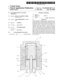
[0016] FIG. 1 shows a longitudinal section of an actuator according to an exemplary embodiment of the invention wherein a selection of annular ferromagnetic discs of different thicknesses is shown separately;
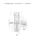
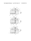
[0017] FIG. 1A shows a greatly enlarged section of the area designated as A in FIG. 1;
[0018] FIG. 2 is an illustration corresponding to FIG. 1A with an associated representation of the resulting characteristic curves without and with an inserted annular ferromagnetic disc, respectively;
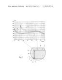
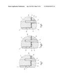
[0019] FIG. 3 is an illustration corresponding to FIG. 2, where an annular ferromagnetic disc with a thickness larger than that of FIG. 2 has been inserted;
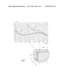
[0020] FIG. 4 is a partial longitudinal section, in which a part of the magnet armature with the actuating member as well as the transition region between the pole tube and the pole core are illustrated in accordance with an exemplary embodiment;
[0021] FIGS. 5 to 9 show partial longitudinal sections of five further exemplary embodiments of the invention corresponding to FIG. 4 and
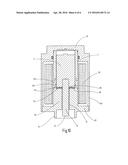
[0022] FIG. 10 shows a longitudinal section of an exemplary embodiment of the actuating device in the form of a compact magnet.
[0023] In FIG. 1, which shows the longitudinal section of an exemplary embodiment of the actuator according to the invention, an associated coil winding has been omitted, which is arranged in a manner known per se on the pole tube denoted by 2 and to which a current can be applied for actuation processes. In the pole tube 2, an armature 4, at one end of which a coaxial rod-like actuating member 6 is attached, is guided in an axially movable manner. This extends through a through hole 8 in a pole core 10, in such a manner that the free end 12 of the actuating member 6 is accessible for an actuating process at a connecting part 14 of the pole core 10. An actuating means connected to the connecting part 14, for example in the form of a valve, is not shown in FIG. 1.
[0024] The example shown in FIG. 1 is designed as a so-called "pushing magnet", wherein the illustrated axial position corresponds to the fully energized state of excitation of the coil winding (not shown) and the armature 4 generating a compressive force via the actuating part 6 as an actuating force. A resetting device, returning the armature 4 upon termination of the energization in FIG. 1 to the right, for example in the form of a return spring, is not shown in FIG. 1, as such a device can be designed according to prior art. To limit the length of the return stroke caused by a restoring force of the piston 4, an end body 18 has been attached to the end of the pole tube 2 attached on the right in FIG. 1 by means of a crimp 16. By appropriate dimensioning of the end body 18, the stroke designed for the return stroke can be set to a desired length. The pole tube 2 is connected to the pole core 10 via a weld 20, which forms a separation area effecting a magnetic decoupling in a manner known per se. The guide formed on the inside of the pole tube 2 for the armature 4 continues through the separation area formed by the weld 20 in a recess 22, which is formed plain cylindrically in the pole core 10 and has a bottom surface 24 located in a radial plane. At the weld 20, the recess 22 terminates at an edge 26 that forms a sharpened edge surrounding the guiding surface of the armature 4.
[0025] In the illustration of FIG. 1 an annular ferromagnetic disc 28 made of a ferritic material, which is penetrated by the rod-like actuating member 6, is inserted at the bottom surface 24 in the recess 22 of the pole core 10. An anti-adhesion disc 30 of conventional type is arranged between the annular disc 28 and the end of the armature 4. The annular disc 28 shown in an inserted state has a relatively low axial thickness. FIG. 1 shows by way of example a selection of insertable annular discs 28 of different axial thicknesses. The thickness of the respective inserted annular disc 28 results in a corresponding shortening of the axial length of the stroke chamber available for armature 4 when moving in the direction of the pole core 10. The modification of the stroke chamber in the critical stroke range, which adjoins the magnetic separation area of the weld 20, affects the magnetic force-displacement curve, as shown in examples in FIGS. 2 and 3.
[0026] Of FIGS. 2 and 3, FIG. 2 shows an example with an inserted annular disc 28 of lower thickness, while FIG. 3 shows an example with an annular disc 28 of greater thickness. In the example of FIG. 2, the characteristic curve in a numbered F-d graph without inserted annular disc 28 is denoted by 32 and with an inserted annular disc 28 of a thickness of 0.7 mm is denoted by 34. As can be seen, the inserted annular disc 28 results, via a mainly to be used standard stroke of approx. 1.5 mm to 2.5 mm, in a largely horizontal characteristic curve, whereas the characteristic curve 32 is inclined there, in contrast. In the example shown in FIG. 3 for an inserted annular disc 28 with a thickness of 1.3 mm, a sharp increase in force results in a higher maximum force with a smaller stroke, cf. characteristic curve 34. One therefore has the choice in manufacturing a pole tube-pole core system in a standard size, to realize a selected course of the F-d curve, depending on whether no annular ferromagnetic disc 28 is inserted or an annular disc 28 of predetermined thickness is inserted. With the same standard size, the stroke of the return stroke can also be determinable by selecting the dimensions of the respective end body 18.
[0027] FIGS. 4 to 9 show further exemplary embodiments with a choice of possible types of the incorporation of an annular disc 28. For instance in the example of FIG. 4, the annular disc 28 is attached to the bottom surface 24 of the pole core 10 by adhesive bonding or brazing. In the example of FIG. 5, a connection is realized by means of mechanical deformation by external caulking the annular disc 28 at 36 against the inner wall of the recess 22. FIG. 6 shows the attachment of the annular disc 28 by means of a sleeve 38, forming the guiding surface for the armature 4 on the inside of the pole tube 2 and the recess 22.
[0028] In the example of FIG. 7, a welded geometry 40 formed on the annular disc 28 is provided as the connecting means, while in the example of FIG. 8 in contrast, a mechanical deformation is provided by caulking the annular disc 28 into an annular groove 42 incorporated in the bottom surface 24. Finally, FIG. 9 shows an example, in which a specially shaped annular disk 28 has, on the side facing away from the armature 4, a coaxial sleeve-like extension 44, which is secured in the bore 8 of the pole core 10 by an interference fit.
[0029] FIG. 10 shows an exemplary embodiment in which the invention has been implemented for a so-called compact magnet. In contrast to the configuration shown in FIG. 1, the pole core 10 is designed shorter in relation to its diameter and has a flange-like radial extension 48 at the end having the connection member 14. The end body 18 forms the closed bottom of a pot-shaped housing 50, which extends up to the extension 48 of the pole core 10, which closes the open end of the pot. Between the end body 18 and the extension 48 of the pole core 10, the housing 50 surrounds the coil winding 52, which in turn surrounds a large part of the pole tube 2 and the pole core 10. For the compact magnet shown in FIG. 10 the course of the F-d curve can be equally influenced by the selection of the introduced ferromagnetic annular discs 28.
User Contributions:
Comment about this patent or add new information about this topic:
Images included with this patent application:
 |  |
 |  |
 |  |
 |
| Similar patent applications: | |
| Date | Title |
|---|---|
| 2016-04-07 | Electromagnetic actuating apparatus |
| 2016-05-05 | Method and apparatus for non-contact axial particle rotation and decoupled particle propulsion |
| 2016-02-18 | Electromagnetic contactor |
| 2016-05-19 | Electromagnetic coil device |
| 2015-10-22 | Electromagnetic relay |
| New patent applications in this class: | |
| Date | Title |
|---|---|
| 2018-01-25 | Electromagnetic actuator |
| 2016-06-16 | Method for manufacturing a pole tube, a pole tube for an electromagnet and a solenoid valve |
| 2016-05-05 | Actuator with transmission element |
| 2016-03-10 | Solenoid actuator |
| 2016-03-03 | Electronic device with signal line routing to minimize vibrations |
| New patent applications from these inventors: | |
| Date | Title |
|---|---|
| 2013-11-28 | Solenoid valve |
| Top Inventors for class "Electricity: magnetically operated switches, magnets, and electromagnets" | |
| Rank | Inventor's name |
|---|---|
| 1 | Larry W. Fullerton |
| 2 | Mark D. Roberts |
| 3 | Kouetsu Takaya |
| 4 | Yasuhiro Naka |
| 5 | James L. Richards |