Patent application title: CONNECTING ASSEMBLY AND CONNECTING DEVICE
Inventors:
Fu-Kuo Huang (New Taipei, TW)
Fu-Kuo Huang (New Taipei, TW)
IPC8 Class: AF16C1106FI
USPC Class:
403141
Class name: Pivoted universal ball and socket divided socket-type coupling
Publication date: 2016-04-28
Patent application number: 20160115991
Abstract:
A connecting assembly includes a first pipe, a second pipe and a
connecting part. The connecting part includes a spherical rotating
portion. The second pipe includes a connecting portion. The connecting
portion includes two clamping parts and defines a sliding groove. The
rotating portion is received between the two clamping parts. The
connecting part rotates around the spherical rotating portion. The
connecting part moves along the sliding groove. The first pipe is
rotatably connected to the second pipe.Claims:
1. A connecting assembly comprising: a first pipe; a second pipe
comprising a connecting portion, and the connecting portion comprising
two clamping portions and defining a sliding groove; and a connecting
part comprising a spherical rotating portion; wherein the connecting part
is fixed with the first pipe, the spherical rotating portion is received
between the two clamping portions, the connecting part is configured to
rotate around the spherical rotating portion, the connecting part moves
along the sliding groove, and the first pipe is rotatably connected to
the second pipe.
2. The connecting assembly of claim 1, wherein the sliding groove is located between the two clamping portions.
3. The connecting assembly of claim 1, wherein the second pipe comprises a pipe body, each clamping portion extends from the pipe body, and the clamping portions are substantially arcuate.
4. The connecting assembly of claim 1, wherein an end of the first pipe has an internal thread, the fixing portion has an external thread, and the external thread is fixed with the internal thread.
5. The connecting assembly of claim 1, wherein the connecting part comprises a body, the body is substantially cylindrical, and a width of the sliding groove is greater than or equals to a diameter of the body.
6. The connecting assembly of claim 1, wherein a width of the sliding groove is less than a diameter of the spherical rotating portion.
7. The connecting assembly of claim 1, wherein the diameter of the first pipe equals to a diameter of the second pipe.
8. A connecting assembly comprising: a second pipe comprising a connecting portion, and the connecting portion comprising two clamping portions and defining a sliding groove; and a connecting part comprising a spherical rotating portion; wherein the connecting part is fixed with a first pipe, the spherical rotating portion is received between the two clamping portions, the connecting part is configured to rotate around the spherical rotating portion, the connecting part moves along the sliding groove, and the first pipe is rotatably connected to the second pipe.
9. The connecting assembly of claim 8, wherein the sliding groove is located between the two clamping portions.
10. The connecting assembly of claim 8, wherein the second pipe comprises a pipe body, each clamping portion extends from the pipe body, and the clamping portions are substantially arcuate.
11. The connecting assembly of claim 8, wherein an end of the first pipe can has an internal thread, the fixing portion has an external thread, and the external thread is fixed with the internal thread.
12. The connecting assembly of claim 8, wherein the connecting part comprises a body, the body is substantially cylindrical, and a width of the sliding groove is greater than or equals to a diameter of the body.
13. The connecting assembly of claim 8, wherein a width of the sliding groove is less than a diameter of the spherical rotating portion.
14. A connecting device comprising: a connecting part comprising a fixing portion, a cylindrical body, and a spherical rotating portion, the cylindrical body extending from the fixing portion, the spherical rotating portion extending from the cylindrical body; wherein the fixing portion is fixed with a first pipe, and the spherical rotating portion is rotatably connected to a second pipe.
Description:
CROSS-REFERENCE TO RELATED APPLICATIONS
[0001] This application claims priority to Taiwanese Patent Application No. 103137104 filed on Oct. 28, 2014, the contents of which are incorporated by reference herein.
FIELD
[0002] The subject matter herein generally relates to connecting assemblies.
BACKGROUND
[0003] Electronic devices, such as computers, typically include a bracket which can include pipes. To support the computer, the pipes need to be connected together.
BRIEF DESCRIPTION OF THE DRAWINGS
[0004] Implementations of the present technology will now be described, by way of example only, with reference to the attached figures.
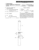
[0005] FIG. 1 is an exploded, isometric view of one embodiment of a connecting assembly.
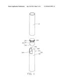
[0006] FIG. 2 is an assembled view of the connecting assembly of FIG. 1.
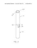
[0007] FIG. 3 is a cross-sectional view in a connecting assembly taken along line III-III of FIG. 2.
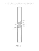
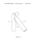
[0008] FIG. 4 is a view of the connecting assembly of FIG. 2 in a working state where a first pipe is angled relative to a second pipe.
DETAILED DESCRIPTION
[0009] It will be appreciated that for simplicity and clarity of illustration, where appropriate, reference numerals have been repeated among the different figures to indicate corresponding or analogous elements. In addition, numerous specific details are set forth in order to provide a thorough understanding of the embodiments described herein. However, it will be understood by those of ordinary skill in the art that the embodiments described herein can be practiced without these specific details. In other instances, methods, procedures, and components have not been described in detail so as not to obscure the related relevant feature being described. Also, the description is not to be considered as limiting the scope of the embodiments described herein. The drawings are not necessarily to scale and the proportions of certain parts may be exaggerated to better illustrate details and features of the present disclosure.
[0010] Several definitions that apply throughout this disclosure will now be presented.
[0011] The term "substantially" is defined to be essentially conforming to the particular dimension, shape, or other feature that the term modifies, such that the component need not be exact. For example, "substantially cylindrical" means that the object resembles a cylinder, but can have one or more deviations from a true cylinder. The term "comprising," when utilized, means "including, but not necessarily limited to"; it specifically indicates open-ended inclusion or membership in the so-described combination, group, series and the like.
[0012] The present disclosure is described in relation to a connecting assembly.
[0013] FIG. 1 illustrates one embodiment of a connecting assembly for fixing pipes. The connecting assembly includes a first pipe 10, a connecting part 20, and a second pipe 30.
[0014] An end of the first pipe 10 can include an internal thread 12. In at least one embodiment, the first pipe 10 is substantially cylindrical.
[0015] The connecting part 20 includes a fixing portion 22, a body 24, and a rotating portion 26. The body 24 extends from the fixing portion 22. The rotating portion 26 extends from the body 24. The body 24 is located between the fixing portion 22 and the rotating portion 26. The fixing portion 22 has an external thread 220. The body 24 is substantially cylindrical. The rotating portion 26 is substantially spherical.
[0016] The second pipe 30 includes a pipe body 32 and a connecting portion 34. The connecting portion 34 is located at an end of the pipe body 32. The connecting portion 34 includes two clamping portions 342. The connecting portion 34 defines a sliding groove 344. The sliding groove 344 is located between the two clamping portions 342. A width of the sliding groove 344 is less than a diameter of the spherical rotating portion 26. The width of the sliding groove 344 is greater than or equals to a diameter of the cylindrical body 24. Each clamping portion 342 extends from the pipe body 32. The clamping portions 342 are substantially arc-shaped and flaky. Two clamping portions 342 cooperatively define a receiving space 346.
[0017] FIGS. 2 and 3 illustrate two views of the assembled connecting assembly. In assembly, the external thread 220 of the fixing portion 22 is fixed with the internal thread 12 of the first pipe 10. The connecting part 20 is fixed with the first pipe 10. The rotating portion 26 is received in the receiving space 346 of the second pipe 30. The clamping portions 342 cover the rotating portion 26.
[0018] FIG. 4 illustrates when in use, the connecting part 20 rotates around the spherical rotating portion 26. The body 24 of the connecting part 20 moves along the sliding groove 344. The first pipe 10 is rotatably connected to the second pipe 30. In at least one embodiment, the diameter of the first pipe 10 is equal to a diameter of the second pipe 30.
[0019] The embodiments shown and described above are only examples. Many details are often found in the art such as the other features of a connecting assembly. Therefore, many such details are neither shown nor described. Even though numerous characteristics and advantages of the present technology have been set forth in the foregoing description, together with details of the structure and function of the present disclosure, the disclosure is illustrative only, and changes may be made in the details, especially in matters of shape, size, and arrangement of the parts within the principles of the present disclosure, up to and including the full extent established by the broad general meaning of the terms used in the claims. It will therefore be appreciated that the embodiments described above may be modified within the scope of the claims.
User Contributions:
Comment about this patent or add new information about this topic:
Images included with this patent application:
 |  |
 |  |
 |
| Similar patent applications: | |
| Date | Title |
|---|---|
| 2016-05-19 | Stabilized miter edge system and device |
| 2016-04-07 | Nested polygonal member locking device |
| 2016-04-28 | In-line rail and component system and method for rapid coupling |
| 2015-11-12 | Mechanical coupling devices |
| 2015-11-19 | Connecting devices |
| New patent applications in this class: | |
| Date | Title |
|---|---|
| 2012-03-15 | Friction ball joint |
| 2011-06-16 | Method for manufacturing a joint and a joint obtainable by the method |
| 2009-06-18 | Light articulation ball-joint and method of manufacture of such a ball joint |
| New patent applications from these inventors: | |
| Date | Title |
|---|---|
| 2022-03-31 | Heating structure, detection chip, and nucleic acid detection device |
| 2016-04-28 | Illumination system |
| 2016-04-28 | Nestable collapsible support apparatus |
| 2016-04-28 | Supporting apparatus |
| 2015-06-04 | Protecting device for tablet device |
| Top Inventors for class "Joints and connections" | |
| Rank | Inventor's name |
|---|---|
| 1 | Steven E. Morris |
| 2 | Jennifer P. Lawall |
| 3 | Yu-Tao Chen |
| 4 | Chun-Che Yen |
| 5 | Te-Sheng Jan |