Patent application title: Lazy Lee
Inventors:
Lee Ralph Goldsticker (Aventura, FL, US)
IPC8 Class: AA47B4900FI
USPC Class:
312326
Class name: Supports: cabinet structure with movable components pivotal, fixed axis (e.g., door)
Publication date: 2016-04-28
Patent application number: 20160113394
Abstract:
"Someone finally figured out how to best utilize the corner" is the most
accurate description of the Lazy Lee. The design is "driven" by two
separate bearing systems working in harmony, to easily hold over two
tons. The unique balancing device that rests on top of the bearing
systems has been designed to create four distinctive sides to a circle by
utilizing an "H" configuration. With the design of our stabilizing pin
system at the top, is not dependent on the on the location of the center
of the "H", we can customize the unit to fit our customers' individual
storage needs.Claims:
1) A bottom assembly comprising: a square sub-plate with a housing for a
thrust bearing in the center and holes for securing the sub-plate to a
cabinet base, a thrust bearing fitted for a sub-plate, a bearing
assembly, a plate with a hole in the center and a rod TIG welded to the
plate in the center
2) A top assembly comprising: a static upper panel, part of the outer cabinet casing, a revolving lower panel, part of the revolving cabinet, a threaded pin, fender washer, tee nut and a bushing uniting the upper and lower panels.
Description:
[0001] The present application also is related to pending U.S. Design
patent application Ser. No. 29/474,544 filed Oct. 22, 2014, which is
incorporated by reference. All of the material from the U.S. Applications
that is essential to the claimed design is included herein. Any material
in the related U.S. Applications that is not present herein forms no part
of the claimed design.
BACKGROUND OF THE INVENTION
[0002] 1. Field of the Invention
[0003] The present invention generally relates to revolving storage cabinets, and more specifically, to rotation devices that spin storage cabinets.
[0004] 2. Description of the Related Art
[0005] Revolving storage cabinets have an advantage over stationary ones by permitting users an easier access to all sides of the cabinet, and thereby maximizing unit's utility. Many of such storage cabinets, such as "Lazy Susan", are relatively lightweight. By contrast, the devices animating rotation of large storage cabinets have shown to be prone to failure for weights over 200 pounds. Therefore, the proposed Lazy Lee system solves the above-mentioned problem.
SUMMARY OF THE INVENTION
[0006] The Lazy Lee rotation mechanism consists of a bottom assembly and a top assembly. The system is configured for use with a storage cabinet situated in between the bottom assembly and the top assembly.
[0007] These and other aspects of the present invention become apparent in the context of preferred embodiment as shown on the drawings. The drawings are for the purpose of describing a preferred embodiment of the invention, and are not intended to limit the present invention.
BRIEF DESCRIPTION OF THE DRAWINGS
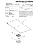
[0008] FIG. 1 is an exploded view of the bottom assembly part of the invention.
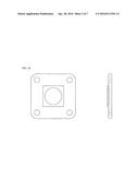
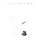
[0009] FIG. 1A is a detail view of a sub-plate.
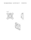
[0010] FIG. 1B is a detail view of a bearing assembly.
[0011] FIG. IC is a detail view of a base plate.
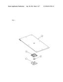
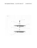
[0012] FIG. 2 is an exploded view of the top assembly part of the invention.
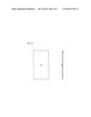
[0013] FIG. 2A is a detail view of a threaded pin, and of a tee nut.
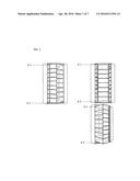
[0014] FIG. 3 shows embodiments of the invention's top assembly A-1, and invention's bottom assembly A-2.
DETAILED DESCRIPTION OF THE PREFERRED EMBODIMENT
[0015] The present invention is a rotation mechanism consisting of a bottom assembly and a top assembly. The invention is configured for use with a storage cabinet situated in between the bottom and top assembly. FIG. 3 shows embodiments of the invention in a storage unit consisting of an outer stationary casing and an inner rotating storage cabinet. FIG. 3 A-1 showing the invention's top assembly, and FIG. 3 A-2 showing invention's bottom assembly. The invention can be adapted to fit other similar configurations.
[0016] FIG. 1 is an exploded view of the bottom assembly part of the invention. It comprises a double bearing system: a bearing assembly 3, and a bearing 2 housed in sub-plate 1. The double bearing system drastically increases the weight load capacity of the invention. FIG. 1 also illustrates the metallic plate 4 which is screwed into the wooden base of a storage cabinet sitting on top and thereby spinning or rotating the cabinet itself.
[0017] FIG. 1A is a detail view of a sub-plate, which is screwed into a stationary housing of the rotating storage. Alternatively, sub-plate is screwed into the floor if the rotating cabinet is a stand-alone unit, that is without stationary housing as shown on FIG. 3.
[0018] FIG. 1B is a detail view of a bearing assembly, which consists of a grease fitting and 2 set screws, freely rotating steel flange bearing with center through hole.
[0019] FIG. 1C is a detail view of a metallic base plate. The metallic base plate is connected to wood base of the cabinet sitting on top and thereby spinning or rotating the cabinet itself.
[0020] FIG. 2 is an exploded view of the top assembly part of the invention. It consists of an upper stationary panel 8 and a lower rotating panel 5; both panels are aligned and held together by a threaded pin 10, fender washer 9, tee nut 7, and bushing 6.
[0021] FIG. 2A is a detail view of a threaded pin, and of a tee nut.
[0022] FIG. 3 shows embodiments of the invention's top assembly A-1, and invention's bottom assembly A-2.
[0023] As used herein the term "storage" or "cabinet" is defined broadly to encompass any number of storage assemblies, organizers, containing drawers, sections or chambers designed to facilitate orderly grouping of various items.
User Contributions:
Comment about this patent or add new information about this topic:
Images included with this patent application:
 |  |
 |  |
 |  |
 |  |
 |
| New patent applications in this class: | |
| Date | Title |
|---|---|
| 2019-05-16 | Electronics enclosure with low-profile door |
| 2016-06-30 | Electronic device enclosure |
| 2016-06-09 | Washing machine |
| 2016-05-19 | Locking device for opening and closing lid |
| 2016-04-21 | Cabinet |
| Top Inventors for class "Supports: cabinet structure" | |
| Rank | Inventor's name |
|---|---|
| 1 | Yun-Lung Chen |
| 2 | Karl-Friedrich Laible |
| 3 | Jae Hoon Lim |
| 4 | Chen-Lu Fan |
| 5 | Wen-Tang Peng |