Patent application title: LED Projection Night Light
Inventors:
Tseng-Lu Chien (Walnut, CA, US)
IPC8 Class: AF21S800FI
USPC Class:
362644
Class name: Quick disconnect-type light unit night light ornamental or decorative
Publication date: 2016-04-07
Patent application number: 20160097499
Abstract:
An LED projection night light for night time or dark area use includes a
plug-in wall outlet night light or direct current operated night light
with projection features to project an image, message, data, logo, or
time on a ceiling, walls, floor, or other desired surface. The LED night
light incorporates optics-lens and Object with preferred focus
calculation to create bigger image to shown on locations. The parts for
make night light including but not limited as an optics-lens, slides,
openings, or cut-outs, and/or a transparent material piece, translucent
material piece, telescope assembly, housing-member, slide-film,
slide-disc, elastic-member, tilt-means, rotating-means, adjust-means,
roller-means, mechanical-means, extend-means, convex lens, and/or concave
lens designed to make the desired image, message, data, logo, or time
project to the ceiling, walls, floor, or other desired surface to be seen
by a viewer. The LED light upgrade model has an interchangeable power
source arrangement, permitting the night light to be selectively powered
by either an AC powered sealed-unit or a DC powered battery-pack.Claims:
1. An LED projection night light, comprising: at least one LED arranged
to emit visible light beams; and at least one power source connected to
said at least one LED to cause said at least one LED to exhibit at least
one of a desired light function, timing, color, brightness, at
illumination effect, wherein: said LED projection night light is a
plug-in light arranged to be connected to a plug-in electrical outlet by
prongs, said plug-in night light includes at least one LED to emit light
to object has tiny image on it and passing though the image magnify
optic-lens to create the Bigger-size image for projecting a desired
image, message, data, logo, or time to project onto a top ceiling,
opposite walls, floor, or other desired surface, said night light has
parts including elements selected from the group consisting of an
housing, tube, optical lens, openings, cut-outs, a transparent material
piece, a translucent material piece, a convex lens, and a concave lens,
and The said LED night light has adjustable construction to change the
bigger-size image to any desired position, angle, locations, and
orientation while people apply force to the said housing or part. The
said Night light incorporate with straight telescope or tube or housing
has LED on one side or end and other side or end has magnify optics-lens
and object fit within the said telescope or tube or housing and
bigger-size image is shown on remote away surface where is not the
surface has outlets for plug-in.
2. An LED projection night light as claimed in claim 1, further comprising said night light includes at least one parts incorporated with the LED for projecting said light through one of a plurality of different object or slides or film to cause a desired image, message, data, logo, or time to project onto a ceiling, walls, floor, or other desired surface and means including a movable slide holding member for enabling to change said one of a plurality of slides to a different slide by moving the slide holding member from a first position in which one of a plurality of slides is in front of said LED to a second position in which said different slide is in front of said LED to change said image, message, data, logo, or time.
3. An LED projection night light as claimed in claim 2, wherein said slides are changed by at least one of said roller with manual or automatically by motor, said elastic member, and a push button.
4. An LED projection night light as claimed in claim 2, wherein said slide is mounted in a rotatable slide disc or compartment or holder which containing said plurality of different slides.
5. An LED projection night light as claimed in claim 1, further comprising at least one of the following elements: (a) a telescope or tube assembly, (b) tilt means for tilting, (c) rotating means for rotating, (d) adjust means for adjusting, (e) a roller, and (f) an elastic member to change a projection direction or optics lens or object or housing of said night light.
6. An LED projection night light as claimed in claim 1, wherein a projection direction or housing is changed by at least one of said rotating, a tilt, a swivel, a housing, and a bend construction(s).
7. An LED projection night light as claimed in claim 1, wherein said parts includes an extend design and said extend design to changes a relative position of said LED, slides, magnify Optics-lens to adjust a focus of said device
8. An LED projection night light, comprising: at least one LED arranged to emit visible light beams; and at least one power source connected to said at least one LED to cause said at least one LED to exhibit at least one of a desired light function, timing, color, brightness, at illumination effect, The improvement wherein: said DC powered night light includes at least one LED to emit light beam to object has tiny image and passing though the image magnify optic-lens to create the Bigger-size image for projecting a desired image, message, data, logo, or time to project onto a top ceiling, opposite walls, floor while LED light put on high locations, or other desired surface, said night light has parts including elements selected from the group consisting of an housing, tube, optical lens, openings, cut-outs, a transparent material piece, a translucent material piece, a convex lens, and a concave lens, and said LED projection night light is a DC powered night light arranged to be supplied with power from any combination of an AC adaptor jack, solar power source, wind power source, a generator, battery, an electricity storage device, USB Power source, and a charging circuit, means for adjusting said parts, said adjusting means including at least one of a telescope assembly, tilt means for tilting said parts, rotating means for rotating said parts, and extend means for extending said parts, and
9. An LED projection night light as claimed in claim 1, further comprising said night light includes at least one parts incorporated with the LED for projecting said light through at least one or one of a plurality of different object or slides or film to cause a desired image, message, data, logo, or time to project onto a ceiling, walls, floor while DC powered LED light install on high location, or other desired surface and means including a movable slide holding member for enabling to change said one of a plurality of slides to a different slide by moving the slide holding member from a first position in which one of a plurality of slides is in front of said LED to a second position in which said different slide is in front of said LED to change said image, message, data, logo, or time.
10. An LED projection night light as claimed in claim 9, wherein said slide is mounted in a rotatable slide disc containing said plurality of different slides.
11. An LED projection night light as claimed in claim 9, further comprising at least one of the following elements: a roller with manual or automatically by motor orand an elastic member to change a projection direction of said night light.
12. An LED projection night light as claimed in claim 9, wherein said slides are changed by at least one of said roller by manual or automatically by motor, said elastic member, and a push button.
13. An LED projection night light as claimed in claim 8, wherein a projection direction or bigger-image locations is changed by at least one of said rotating, said tilt, a swivel, a housing, and a bend construction.
14. An LED projection night light as claimed in claim 8, wherein said parts includes said extend construction and said extend construction changes a relative position of said slides, said LED, and said magnify optic-lens to adjust a focus of said Night light.
15. An LED projection night light, comprising: at least one LED arranged to emit visible light beams; and at least one power source connected to said at least one LED to cause said at least one LED to exhibit at least one of a desired light function, timing, color, brightness, at illumination effect, wherein: said LED projection night light is a AC powered or DC powered night light arranged to be connected to a plug-in electrical outlet or get DC power from an AC adaptor jack, or solar power source, or wind power source, or a generator, or battery, or an electricity storage device, or USB Power source, or a charging circuit, The said night light includes at least one LED to emit light to object has tiny image on it and passing though the image magnify optic-lens to create the Bigger-size image for projecting a desired image, message, data, logo, or time to project onto a top ceiling, opposite walls, floor, or other desired surface, said night light has parts including elements selected from the group consisting of an housing, tube or tube assembly, magnify optical lens, housing openings, housing cut-outs, a transparent material housing piece, a translucent material housing piece, a convex lens, and a concave lens, and The said Night light has adjustable construction to change the bigger-size image to any desired position, angle, locations, and orientation while people apply force to the said housing or parts of the said night light. The said Night light incorporate with straight telescope or tube has LED on one side or end and other side or end has magnify optics-lens or assembly and object fit within the said telescope or tube or housing and bigger-size image is shown on remote away surface where is perpendicular or vertical with LED light beam.[IC1] The said Night light the LED light beam vertical or perpendicular traveling though Object, slide, film, magnify function optics-lens to form the bigger-image. The said night light has more than one object(s), slide(s), film(s) arranged on disc, holder, compartment device which can be changeable, replaceable.
Description:
[0001] This application is a continuation of U.S. patent application Ser.
No. 14/539,267, filed Nov. 12, 2014, which is a divisional of U.S. patent
application Ser. No. 14/275,184, filed May 12, 2014, which is a
divisional of U.S. patent application Ser. No. 12/318,470, filed Dec. 30,
2008, each of which is incorporated herein by reference.
[0002] This application is a divisional of U.S. patent application Ser. No. 11-806,285, filed May 31, 2007, incorporated herein by reference.
DESCRIPTION
[0003] This application has subject matter in common with that of U.S. patent application Ser. No. 12/292,153 ("LED night light has projection or image feature"--(# DD-1) Now U.S. Pat. No. 7,871,192); Ser. No. 12/318,470 ("LED night light with Projection features"--(#EE)Now U.S. Pat. No. 7,832,918); Ser. No. 12/149,963 ("Removable LED light device"--#AA-Now U.S. Pat. No. 7,722,230); Ser. No. 12/073,889 ("LED track light device"=(#X) Now 8,827,511); Ser. No. 12/073,095 ("LED light with changeable position with Preferable power source"--(#Y) Now U.S. Pat. No. 7,726,869); Ser. No. 12/007,076 ("LED light with changeable geometric system" (#W-08)--Now 7,726,861); Ser. No. 12/003,691 ("LED light with changeable geometric dimension features"=(#V) Now, U.S. Pat. No. 7,726,839); Ser. No. 12/003,809 ("LED light with changeable features"--(#S-07) Now U.S. Pat. No. 7,618,150); Ser. No. 11/806,711 ("Multiple LED light with adjustable angle features"--(#T)); Ser. No. 11/527,631 ("LED Night light with interchangeable display unit"--(J-06)); Ser. No. 11/498,881 ("Poly Night light"); Ser. No. 11/255,981 ("Multiple light source Night Light"); Ser. No. 11/094,215 ("LED Night light with Liquid optics medium"); Ser. No. 11/092,741 ("Night light with fiber optics"); Ser. No. 10/883,747 ("Fiber Optic light kits for footwear"); Ser. No. 11/498,874 ("Area Illumination for LED night light"); Ser. No. 11/527,629 ("Time Piece with LED night light"); ("Multiple Function Night light with Air Freshener"); Ser. No. 11/806,284 ("LED Night light with more than one optics medium" (Q) Now U.S. Pat. No. 7,632,004)); Ser. No. 11/806,285 ("LED Night Light with multiple functions"--(#R)); and Ser. No. 11/806,711 ("Multiple LEDs Light with adjustable angle function"--(#G-05) Now U.S. Pat. No. 7,677,745).
BACKGROUND OF THE INVENTION
[0004] The current invention projects a colorful image on a wall or ceiling at a desired location to enable people to view an image such as character, logo, message, animals, logo, time, space shutter, stars, moon, planet, silver-river, or a universal image and cause the people to have a pleasant mood when in a dark environment, or to fall asleep in a nice environment. it is especially important for youth or kids room applications to let them have their own favorite image surround them. It is also a great advertisement medium that not only promotes things but also offers a night light for illumination.
[0005] In a preferred embodiment, the current invention can take the form of a plug-in wall outlet LED night light having projection features to project the image, message, data, logo, and/or time on a ceiling, walls, or floor, or any other desired surface.
[0006] The night light of the current invention has as a light source an LED or LEDs, which may be the same as described in co-pending #H-05 U.S. patent application Ser. No. 11/255,981 (now U.S. Pat. No. 7,455,444) to provide a visible light beam that passes through an optics means or more than one optics means (as described in co-pending #Q-07 U.S. patent application Ser. No. 11/806,284 Now U.S. Pat. No. 7,632,004) and creates an image at the desired location, preferably with one or more features selected from group including size, dimension, area, height, distance, color, brightness, time period, and trigger means. The current invention represents a big improvement over all U.S. prior art including the following U.S. patents:
[0007] Prior art U.S. Pat. No. 5,517,264 (Sutton) discloses a projection night light with a preferred 7 Watt bulb (408) which radiates too much heat so that a big distance from the bulb to the optics means is required. Because of the super high heat from the 7 Watt Bulb, the night light requires use of a glass material which is very big and dangerous to a user. Furthermore, the Sutton concept of using a glass reflection lens (604) to enable the image to be seen on the display screen (102) requires too complicated a construction and is not practical for a low cost application. In addition, the glass lens is much too fragile, and also is too heavy for the prongs to stay tightly in the outlet.
[0008] The Sutton device the object (here as sticker or film) on the side-window and the bulb (408) to lighted the object's image so the image will present and reflected by the glass reflection lens (604) into the tube and to show on the top ceiling. The other major difference including:
(a) Sutton use the reflection theory to form the top ceiling image, The current invention is use refraction theory to form the image (b) The physic theory different to apply for Sutton and current invention so the construction is totally different (c) The Sutton use reflection lens (604) and need to put slide so the tube diameter have to be big enough so can load the tilt lens (604) v.s. current invention the tube diameter almost same as LED diameter so the Sutton tube is way big than current (d) current invention tube diameter close to LED diameter so can use small diameter Object/slide and position direct up of LED because LED is no-heat light source and will not melt or deform the said plastic material object/slide/film (e) The slide can use small diameter so cost is very low (f) the tube diameter is small close to LED diameter so top optics-lens also can be very small for this very expensive optic-lens so can save a lot of cost too (f) The small tube & LED & slide & optic-lens (4 major parts) small so cost drop a big, But also the housing can make smaller too because all major 4 parts is small so can make compact size for plug-in and easily to pass test lab for pulling and weight testament for US safety requirement needed. (g) The LED light beam of current invention is straight emit to Object/slide/film tiny image the tiny image been lighted and straight emit to the top magnify function Optics Lens magnify to bigger image emit out from top opening of housing. All the light beam is straight move forward and all LED light beam hit the said Slide & Optics-Lens is vertical or perpendicular to the light beam.==>This is totally different with the Sutton disclosure and teach in concept, physics theory, light traveling, parts arrangement, cost, construction, so this is not can comparable in any aspects.
[0009] Prior art U.S. Pat. No. 7,267,444 (Black, Jr.) discloses a projection night light which has the same problems as Sutton's, including use of too many lenses including (303) reflector mirror, (105) (405) condensing lens, (106) (406) adjusting lens, (403) grating lens (which grating lens corresponds to the one disclosed in the inventor's U.S. Pat. No. 5,667,736), and (415) project/object lens. Some of these lens need to made of a glass material which is very fragile and will be broken because it is too heavy to hold tightly in an outlet. The Black patent also emphasizes that the night light disclosed therein projects an image onto a surface parallel to a path of the light beam, through the use of projection means on top of the night light's wall. This is the reason why Black needs a lot of special optics lenses and slides (109) (209) (309) (409) between the glass lens. The major difference between Mr. Black and current invention including:
(1) Major Difference for Mr. Black with Current Invention: Mr. Black discussed for Toy or other hand-held device which has both the slide projector and the overhead projector, the projected image can be easily focused because the distance from the objective lens to the surface is substantially similar for the entire projected image Mr. Black claimed:
[0010] Normally, a slide projector comprises a light source (101) that projects light towards a slide (109) that includes a representation of an image. The light source (101) may have a reflective mirror (not shown) to reflect scattered light back
towards the slide, and a lens 105 may be interposed between the light source (101) and the slide (109) to further concentrate light onto the slide. While a condenser lens is shown, a no-sphere (plano-convex) lens could also be used for this purpose. The light beam then passes through a projection/objective lens (115) that magnifies the image and projects it for display onto a surface (120), like a screen or Wall. A field lens (not shown) could also be provided that further focuses the entire light beam passing through the slide (109) onto the objective lens (115). The light source (101), slide (105), and objective lens (115) are aligned along a common axis of light. In both the slide projector and the overhead projector, the projected image can be easily focused because the distance from the objective lens to the surface is substantially similar for the entire projected image Therefore, the entire projected image can be at a substantially similar distance from a focal point of the objective lens.
[0011] The Black discuss the device use too many optics-means including (1) Reflective mirror (not shown)+Lens(105)+Condenser lens or(Plano-convex lens)+projection/object lens (115)+A field lens (Not shown) for FIG. 1 discussion which mainly for bulb application which the light source has radiant light beams so need the reflective-mirror (not shown) to help get all the backward light beams collected to emit to front areas. Difference including (1-1) The current invention only has max. 2 lens (1-2) The Mr. Black the image size=distance from optic-lens to surface so this is toy or hand-held device. The current invention the image is top of the 12 feet away from the optic-lens for distance and Bigger-Image is not 12 feet big which many only 2 feet so this is totally difference for hand-held or toy application.
(2) Major Difference for Mr. Black with Current Invention:
[0012] Mr. Black design the Night light project image which is parallel with light beam traveling path.
[0013] Mr. Black has The fresnel lens 313 changes the direction of light and focuses it towards the projection/objective lens 315. The objective lens 315 has a surface, Which may be asymmetrical, and can be at an angle of about Zero (0) degrees to about twenty (20) degrees, but an angle of about ten (10) degrees is shown. Ideally, the fresnel lens 313 is disposed at substantially the same angle as the objective lens 315. Light then passes through the objective lens 315 where the image is projected onto the substantially parallel surface.
[0014] The current invention has no any device to change the light traveling direction so the light beam strike the slide and optic-lens to magnify the image from tiny to bigger-size and the Bigger-image is shown on vertical or perpendicular of the light beam traveling path. Further the current invention has movable housing can use finger to change the bigger-size image location, position, orientation at any time. So the major difference between Mr. Black and Current invention (2-1) different optics theory, Mr. black use reflection and Fresnel lens, Current invention simple one of convex lens (2-2) light performance, Mr. Black to make the light beam turn direction, the current invention keep all light beam straight forward (2-3) the different number of the optics-lens, function, construction, cost, light performance (2-4) the image or the result of the concept is different (2-5) Night light construction and features is different and current invention can project to anywhere with housing adjustable means.
Other Prior Art Includes:
[0015] U.S. Pat. No. 6,824,296--Souze et al--Rotating lens with Bulb (78).
[0016] U.S. Pat. No. 6,889,918--Yaniv--Projector is wearable and projects an image onto screen (12).
[0017] U.S. Pat. No. 7,329,035--Feliciano--Child Night Light for held or worn.
[0018] U.S. Pat. No. 7,438,446--McCann--Projector inside a hinged top box (20), None of these can pass a USA safety standard because they will pass weight and pulling tests. Not safe and not qualified at all.
[0019] 1. The current invention preferably LED light source incorporates with Object (image carrier) and optic-lens (magnify the small image to bigger-size image) basing on physics lens and focus theory to create bigger image on desired locations and also incorporate with other parts means such as an optics-lens or concave lens, and/or a tube/tube assembly/telescope (hereafter as telescope) construction, openings, cut-outs, plastic parts including transparent or translucent, and a housing-member in rectangular or any geometric shape to create the preferred bigger-size image at the desired location to enable the viewer to see the image and also but not limited to offer illumination for a dark environment.
[0020] 2. The current invention can also have a different construction which enables a person to change the slides by a roller or push button or automatic changing device, other mechanical means. This will enable one night light to exhibit a plurality of different images that can be selected to project on the desired location
[0021] 3. The current invention also may utilize an parts-means having adjust-means to adjust the optics-means at any time and change the position of the image to any desired location by a tilt, rotating, or swivel mechanism, or adjustment-facilitating other construction by finger force can make the bigger-size image change locations. For Desktop DC powered unit can simple move the unit can simple change the image location is also inside the current scope for changing image location.
[0022] 4. The current invention may also enable a focus of the image to be adjusted by providing an extend-means that causes a housing-member or tube/tube assembly/telescope unit (hereafter as telescope) to extend to change the inside lens related position to the said object and change the position of a slide, light source, and/or lens.
[0023] 5. The current invention may furthermore use a very simple tube/tube assembly/telescope construction (hereafter as telescope) to enable the projection-means may including the Objects (image carrier) and/or optics-lens (magnify the small image to bigger-size image) to be easily assembled within the said tube/tube assembly/telescope (hereafter as telescope) and incorporate with parts means as above discussed into a related housing-member to become a finished LED projection night light.
[0024] 6. The current invention utilizes physics or optics lens theory to cause the projected image to have a desired size, clearance, details, brightness, or other image specification.
[0025] 7. In addition, the current invention may use the "interchangeable power source described in several of the Inventor's co-pending-cited U.S. patent applications. The interchangeable power source device encloses all electric components, including a prong, circuit, trigger means, and/or an LED or LED connector, and seals the electric components within the "sealed housing" to provide a safe AC power source to turn on and turn off the said LEDs. The "sealed-housing" also can be replaced by a battery-pack which has all electric components within, including batteries, circuitry, trigger means, and/or an LED or LED connector within to cause the night light to illuminate according to a pre-determined function, timing, duration, and/or effects. This interchangeable battery-pack and sealed-unit of the night light enables the "power source" to be changed from AC to DC or DC to AC. It is appreciated, the current invention just a simple DC powered or AC powered products not limited for a 2 way powers unit in one piece as above and co-pending discussed said interchangeable products.
[0026] 8. The current invention incorporate the LED light which has narrow light beam (around 30 degree) so can fit into small diameter of the tube/tube assembly/telescope tube (hereafter as telescope) channel to allow all light beams do not leakage out. Some preferred construction use the outside housing to prevent the light beam leakage out still fall within the current invention scope as long as the tube/tube assembly/telescope or outside housing or housing parts prevent from LED light leakage out still fall within the current scope.
[0027] 9. The current invention has but not limited small diameter of the tube/tube assembly/telescope tube (hereafter as telescope) which has slide fit within basing on focus theory so the small diameter tube channel only need small diameter or shaped Object (image carrier such as film, slide or changeable digital data display/screen) also can become very small for cost saving.
[0028] 10. The current invention has small diameter of telescope tube which has optic-lens to enlarge the Object's tiny image to bigger-size image which is very expensive so can make image spread out to bigger-size image but while fit into small diameter telescope tube so can also make very small diameter of this expensive optic-lens so can save a big cost for the small diameter of optics-lens. For some application, the Optics lens can fit on the lens-holder within one tube of the said tube assembly and movable along the screw-track or raised-track or groove piece to change the optic-lens in front of the object (image carrier) to change the focus.
[0029] 11. The current invention incorporate the LED, Object, optics-lens and telescope or tube or tube assembly to form the Bigger-size image which LED light beam emit direct to object, optics-lens along the tunnel or channel of the said straight telescope or tube and the light beam is emit vertical or perpendicular to said Slide and Optics-lens.
[0030] 12. The current invention incorporate with optics leans which has refraction properties so can magnify the small object's carried image to bigger-size image.
[0031] 13. The current invention the said non-heat LED light source is put under or after the object which preferred for plastic slide or plastic film and the non-heat LED will not damage the said plastic slide or film for heat-issues which existing on all Bulb or incandescent or other light source which has heat-issues so can not put heated light source direct under the plastic slide or film.
[0032] 14. The current invention the said telescope or tube which is a elongate shape device may in one piece of several pieces to assembly together so can well install the said object and optics on desired location basing on focus theory to get desired bigger-size image.
[0033] 15. The current invention the said Object which carry the image can be several types (1) fix image (2) Several image in a holder means such as disk, roller (3) Changeable digital data but limited range to change such as time always only 88:88 change range (4) Changeable digital data is pre-designed inside the device such as recorder, SD card, digital storage device(s) (5) Changeable digital data is get from wireless, wifi, internet, website or from electric signals transmitting and receiving. Which all belong to current invention said Object which has image carried.
[0034] 16. The said Night light has adjustable construction to change the bigger-size image to any desired position, angle, locations, and orientation while people apply force to the said housing or parts of the said night light. For DC powered unit just move or change the light position or orientation can easily change the image locations.
[0035] 17. The said Night light incorporate with straight telescope or tube has LED on one side or end and other side or end has optics-lens and objet fit within the said telescope or tube and bigger-size image is shown on remote away surface where is perpendicular or vertical with LED light beam. [IC1]
[0036] 18. The said Night light the LED light beam vertical or perpendicular traveling though Object, slide, film, magnify function optics-lens to form the bigger-image.
[0037] 19. The said night light has more than one object(s), slide(s), film(s) arranged on disc, holder, compartment device which can be changeable, replaceable.
[0038] 20. The said night light includes at least one parts incorporated with the LED for projecting said light through one of a plurality of different object or slides or film to cause a desired image, message, data, logo, or time to project onto a ceiling, walls, floor, or other desired surface.
[0039] 21. The said Night light has means including a movable slide holding member for enabling to manually or mechanically or automatically change said one of a plurality of slides to a different slide by moving the slide holding member from a first position in which one of a plurality of slides is in front of said LED to a second position in which said different slide is in front of said LED to change said image, message, data, logo, or time.
[0040] 22. The said Night light has slides are changeable or replaceable and changed by at least one of said roller, said elastic member, and a push button.
[0041] 23. The said slide is mounted in a rotatable slide disc or compartment or holder which containing said at least one or plurality of different slides.
[0042] 24. The said Night light further comprising at least one of the following elements: (a) a telescope or tube assembly, (b) tilt means for tilting, (c) rotating means for rotating, (d) adjust means for adjusting, (e) a roller, and (f) an elastic member to change a projection direction or said focus or optics-lens of said night light.
[0043] 25. The said Night Light has a projection direction or said focus or optics-lens is changed by at least one of said rotating means, said tilt means, a swivel means, a housing means, and a bend means.
[0044] 26. The said Night light said parts includes an extend means and said extend means changes a relative position of said LED, slides, Optics-lens to adjust a focus of said device.
[0045] Finally, the current invention can combine the arrangements disclosed in the inventor's co --pending #H-05 U.S. patent application Ser. No. 11/255,981 and #Q-07 Ser. No. 11/806,284 for more than one light source and more than one of optics means with the arrangement described in the inventor's U.S. Pat. No. 5,667,736 for a grating or hologram to create a variety of different images and obtain an optimal image projection on the wall, ceiling, or floor, as required.
BRIEF DESCRIPTION OF THE DRAWINGS
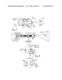
[0046] FIG. 1 illustrates a first preferred embodiment of an LED projection night light, in the form of a plug-in type night light to connect with an electric wall outlet. As shown in FIG. 1, the night light has a super bright white LED incorporated with telescope or tube or tube assembly, and a plurality of slides that serve as an Object(s) have image carried and LED light beam pass though the said tiny image and the said magnify optic-lens to create an bigger-size image at a desired position while allowing the image to be changed at any time.
[0047] FIG. 1A illustrates the manner in which the telescope/tube/tube assembly and slides and optics-Lens and LED relation of FIG. 1 The said telescope/tube/tube assembly are placed in front of the super bright LED to allow a clear bigger-size image to be projected out from the other end of the said telescope/tube/tube assembly to the desire location. This is the current invention basic model. The slide or object or LED or Lens can be install on install-means of said LED light housing which is not on the said tube/tube/telescope assembly depend on the product design.
[0048] FIG. 1B shows a roller or disc or holder in which a plurality of object(s) (here as slides) can be installed and which can be assembled into the night light housing-member to enable the object(s) or slides to be changed at any time to select a preferred image.
[0049] FIGS. 2 and 3 illustrate a second preferred embodiment of an LED projection night light with changeable object(s) or slides installed in a roller. In addition, FIGS. 2 and 3 illustrates a night light with a "interchangeable power source sealed-unit" for electric components such as a prong, circuit, trigger means, LED or LED connector, the components being sealed within the "interchangeable power source sealed unit" to pass all relevant home appliance safety standards required for certification without having to separately certify the night light in which the interchangeable power source sealed unit is included even when the construction of the night light, apart from the electrical components, is changed, and the "interchangeable power source sealed unit" being replaceable by a "battery pack" to change from an AC power operated night light to a battery or DC power operated night light. It is appreciated, the current invention just a simple DC powered or AC powered products not limited for a 2 way powers-unit in one piece as above and co-pending discussed said interchangeable power products. The said tube/tube/telescope assembly has its preferred length and assembly so the arrangement or installation all parts within the outer non rotatable, swivel, tilt housing can be any desired locations which including but not limited including the said LED, optic-lens, slide, magnify lens in single piece or sealed within a movable tube. To change the project image location for non=swivel, rotable, tilt outside housing for DC power products can just simple move or change the orientation of the said LED light can simple change the Bigger Image location for surface top applications so can see clear image without hand-shake to make eyes tired and cause eyes sick or problem.
[0050] FIGS. 4 and 5 illustrate a third preferred embodiment of an LED projection night light, which includes adjust-means to change the projector direction by rotation housing or parts means. FIGS. 4 and 5 also show that the night light has a "interchangeable power source sealed-unit" for all electric components similar to the sealed unit of FIGS. 2 and 3, to allow different night lights to pass all home appliance safety standards and achieve certification without having to undergo separate testing of the different night lights which only has the shade or non-electric parts been changed in which the common safety unit is included. The "interchangeable power source sealed unit" of FIGS. 3 and 4, like that of FIGS. 2 and 3, can be replaced by a "battery pack" to change from an AC power operated night light to a battery or DC operated night light.
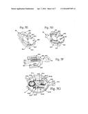
[0051] FIGS. 5A to 5G show details of a mechanical means which can change the slides by push-button, and further that the night light has a "interchangeable power source sealed-unit" of the type described above in connection with FIGS. 4 and 5.
[0052] FIGS. 6-8 illustrate a fourth preferred embodiment, including details of a housing-member, parts means, telescope assembly, LED, Object(s)/Slide, and optics lens, to provide an basic construction with alternative housing construction of an LED projection night light. All these embodiments has the outside housing has either one or movable or non-movable housing parts and all parts some install within the movable tube assembly, some install on the movable or non-moveable housing.
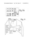
[0053] FIG. 9 shows an LED projection night light utilized for indoor applications and the said LED light may has project light or but not limited for 2nd LED or LEDs for pinhole image light to show the variety pin-holes shaped image which all same color from same LED or LEDs or glow night light for illumination.
[0054] FIG. 9A shows preferred many type of telescope and Optic-Lens assembly examples.
[0055] FIGS. 10-12 illustrate an optics-Lens theory has (object Optic-lens and focus & image relation) used by the current LED project light invention and application of the theory to create a desired image which as long as to use non-heat, non-radiation light source and the slide/film can put on right top position without any deforming, destroy application should be fall within the current scope invention and all LED, Object, image, optics lens, magnify-lens related relations similar for this arrangement still fall within the current invention scope with its alternative, same function, equivalent, replacement, upgrade, modification still should be consider into the current scope of the invention and the all above listed co-invention details descriptions.
DETAIL DESCRIPTION OF THE PREFERRED EMBODIMENTS
[0056] The LED night light with projection features of the current invention is different from a conventional projection pen, projection key chain, projection toy, or commercial presentation projection equipment. One difference is that it is used mainly for night light applications with an LED or LEDs as a light source to directly plug into an outlet device, and as a result the circuit needs to be specially designed to make use of AC 120V 60 Hz input power to change to the drive current for the LED or LEDs.
[0057] The current invention LED project light incorporates LED to supply white light beam to emit the object which location within the telescope tube and pass though the optics-lens to magnify object's tiny image to create the said Big image, The said LED night light has part-means, which may include an optics-lens, slides, openings, cut-outs, a transparent material piece, a translucent material piece, a telescope assembly, a housing-member, a slide-disc, roller-means, an elastic-member, tilt-means, rotating-means, adjust-means, roller-means, mechanical-means, extend-means, a convex lens, a concave lens, and other elements calculated and designed to make the image, message, logo, characters, sign, time, and data project onto a desired surface such as a top ceiling, opposite walls, floor, or any other desired location and bigger-size image can change location while the said housing or part-means been moved, tilt, rotate, spin.
[0058] The current invention also may provide a geometric design for the whole night light, and is not limited to the preferred embodiments. An alternative construction for the night light, for example with different tilt, swivel, rotating, bigger-size image-position-change, focus-adjustable means, and/or slide-change features should still fall within the scope of the current invention.
[0059] As shown in FIG. 1, a preferred LED projection night light (1) has a telescope assembly (1b) that fits within a body with a top opening (1e) to project the image to a top area to form an image having a certain bigger-size (1g) at a certain distance from the opening (1e). The night light body has a built-in mechanism or mechanical-means for installing a roller-means (1c) with a plurality of slides (1d) (1d') (1d'') so that people can change slides at any time and project different images on the area (1g).
[0060] As shown in FIG. 1A, the telescope-assembly (1-1) has a housing-member with an Top-end (1-2) having a preferred optics-lens (1-5) and lower-end (1-3) having LED. The slide (1-6') fitting within the telescope-assembly (1-1) to let LED light beam to pass though. The Alternative arrangement has one optional optic-lens (1-7) and This optional lens function is to change the input narrow LED light bean to spread out to parallel surface light beam which is not needed while telescope's diameter is smaller than LED narrow view angle, and this optional optics-lens (1-7) need put between LED light source and slide so can has broad enough LED light beam to lighted whole slide (1-6') surface to lighted whole tiny image of the Slide. The lens (1-7) and slide (1-6') can have preferred different positions for different image requirements. The convex lens of arrangement (B) faces inside to make incoming LED light beams into parallel light beams as they hit the slide (1-6') so the lighted the tiny image of slide (1-6') will be very clear and every area almost same brightness without dark or brighter areas difference.
[0061] The current invention has the basic embodiments which only has the (1) LED on the lower-end of telescope tube, (2) Object has tiny image (here in slide type) fit within the telescope tube, (3) Optic-lens on the top-end of telescope tube and LED light beam lighted the object's tiny image and lighted image pass though the top optics-lens to magnify to bigger-size image and come out from housing opening end. The housing has construction to install above (1)(2)(3) and its preferred AC or DC power with circuit means, switch means, sensor means or other electric or electronic parts & accessories to make a complete LED project Night Light.
[0062] The arrangements of slide (1-6) do not need optional Optics-lens (1-7) because the LED view angle is Bigger than the said telescope tube's diameter so all LED light beam can emit into the tube without problem to has good light beams. It will be appreciated that alternative arrangements for the telescope-assembly will still fall within the scope of the current invention. These may utilize the alternative constructions illustrated in FIG. 9A. The optics lens, telescope length and more than one pieces to form a straight tube, lens diameter, and/or focus can all be well designed to get a desired bigger-size image quality and size out of the LED projection night light.
[0063] As shown in FIG. 1B, the roller-means has a base (1-10) which has certain holes (1-11) (1-11') (1-11'') and poles (1-12) (1-13) to hold the plurality slides in position and also receive incoming LED light beams so that they hit one of the slides to project colorful images on the slide to a desired location at a certain distance. Some applications do not need the roller-means for a plurality of slides. So long as the slide-film has fixing-holes, there is no need for any roller-means to help hold the slide-film. The current embodiment, however, lets people rotate the roller-means in order to enable people handle and change slides or even can change the roller-means (1-10) from the housing cut-outs.
[0064] FIG. 2 illustrates a plug-in LED night light (2a) with projection features. At least one LED (2d) serves as a light source to supply visible and non-hot light beams. At least one of the telescoping tube (2m) incorporates an LED or LEDs on lower-end, Object-slide(s)-film (2i), film fit within the telescope tube (2m), one optics-lens (21) install between the Top end of telescope tube and housing openings (2K) so these basic parts to create the Bigger-image while the LED light pass though the Slide (2i) and top optics-lens (21) and come out from housing opening (2k). The other parts including of cut-outs (2j) allow the slide-roller can rotate or replace, a transparent top-housing material piece, translucent material base (2a), prong means (2b) help to make a pretty out-looking night light to project a desired image, message, data, logo, or time on a Top ceiling, opposite walls, floor, or other desired surface. At least one of a power source (2b), circuit means (inside of 2a), and trigger means (2c) are arranged to work with the LED or LEDs to provide a desired light function, timing, colors, brightness, and/or illumination. The LED projection night light device (2a) has a changeable object here as slide (2i), film, and changeable of bigger-image angle, position, orientation, and changeable of light functions, and/or light effects features.
[0065] As shown in FIG. 2, the current invention may also use the "interchangeable power source sealed-unit" described in the U.S. patent applications of the inventor that are listed below. The "interchangeable power source sealed unit" contains all electric components including for example a prong, circuit, trigger means, and LED or LED connector, which are sealed within to safely enable an AC power source to turn on and turn off the LEDs. The "interchangeable power source sealed-unit" also can be replaced by a battery-pack which has all electric components within, including batteries, circuit, trigger means, LED or LED connectors, to cause the night light to illuminate and exhibit a predetermined function, timing, duration, and/or effects. The "interchangeable power source sealed unit" is described in detail in the following U.S. patent applications, which are herein incorporated by reference:
[0066] (1) U.S. patent application Ser. No. 11/527,631 ("LED Night light with interchangeable display unit").
[0067] (2) U.S. patent application Ser. No. 11/498,881 ("Poly Night light").
[0068] (3) U.S. patent application Ser. No. 11/255,981 ("Multiple light source Night Light").
[0069] (4) U.S. patent application Ser. No. 11/094,215 ("LED Night light with Liquid optics medium").
[0070] The LED light of this embodiment includes a base having an empty inner space arranged to receive a "interchangeable power source sealed unit" of the type disclosed in the above-listed applications with the above discussed circuit-means, sensor-means, switch-means, timer-means, IC-means, prong-means etc.
[0071] The "interchangeable power source sealed-unit" with its own power, LED, circuit-means, and attachment means is arranged so that it can fit into any LED light housing as long as the housing has a uniform compartment. The "AC powered sealed unit" is arranged to be connected to a 110 Volt 60 Hz or other high voltage connection while meeting all safety standards to make sure that the night light does not present any hazard, risk of electrical short circuit, or potential damage by being subjected to multiple testing standards and procedures for related safety certification.
[0072] The uniform compartment in the LED light housing is constructed and has dimensions so it is easy to design the "interchangeable power source sealed-unit" to fit into this compartment. The current invention also provides a "DC battery-pack" which has its own outside dimension similar to that of the "sealed unit" so that it can fit into the "uniform compartment" too. The "DC powered battery-pack" can replace the "AC powered sealed-unit" at any time because both have their own power, LEDs, circuit-means, and attachment means that enable it to fit the same LED light housing as long as there have uniform compartment.
[0073] As a result, the LED light of the illustrated embodiment can change its power source from AC to DC or DC to AC. This is a further improvement over the "AC power sealed-unit" above-listed patent applications of the inventor. This is big improvement that not only saves a lot of tooling for different shape LED lights but also saves a lot of safety testing laboratory expense and time. Furthermore, the interchangeable power source also can save a lot of tooling cost and time and labor and still provide a good LED light having a pinhole-imaging function (or other LED lighting fixture, laser LED light device, etc.) with a same nice shape but with different power sources to enable the light to be put in different locations where people stay. This is one of the big features of the current invention. Not only all different shapes of LED night light, but also a traditional puck light, can be powered by a DC battery and also by AC as long as people pay for extra parts that let the traditional puck light be plugged into an AC outlet.
[0074] However, the current invention not only has this interchangeable power source model. It also has the model only has Plug-IN prong and powered by AC Power for less cost to make the products. It also has the model Only has DC powered by batteries, USB charger, DC power charger, DC energy storage device, wireless charger device all supply the DC current to the said LED project Night light.
[0075] As shown in FIG. 2, the LED night light (2a) has a base with prong (2b), sensor (2c), and a preferred circuit inside the base to turn on the LED or LEDs to supply a light beam that projects an tiny image on the slide(s)(2i) to the top ceiling for Bigger-size image. The night light has a top housing having an opening (2K) to allow the telescope (2m) and optic-lens (21) to be installed and project the slide (2i) tiny image and magnify by top optic-lens (21) to bigger-size colorful image to the top ceiling from the top housing opening (2K). The top housing also has a cut-out (2j) to allow the rotatable slide-disc (2g) to be installed and the slides (2i) to be changed by rotating the slide-disc (2g) to one of a plurality of the slides (2i).
[0076] FIG. 3 shows more details of the construction of the embodiment of FIG. 2. As described above, this embodiment includes a prong (3b) on the night light (3a) with a top housing (3n) having a top opening (3c) to allow the telescope (3e) to be installed and the image to be projected through the top optics-lens (3d) to the ceiling. The rotatable slide-disc (3g) has a plurality of slides (3k) (3k') (3k'') securely installed on the discs (3i) (3i') (3i'') so that rotation of the disc (3g) enables a user to easily change the slide and project the preferred image on the ceiling. The top housing (3n) has a cut-out (3f) to allow the rotating slide-disc to be properly installed.
[0077] FIG. 4 illustrates another embodiment of a plug-in LED night light (4a) with projection features. At least one LED (4d) serves as a light source to supply visible light beams. At least one telescope (4c) is incorporated with the LED (4d) or LEDs or slide(s) (4d1), film (4d1), housing top-openings (4e), a transparent material housing piece (ball), a translucent material housing piece (Frame and base), to project the desired image, message, data, logo, or time on the top ceiling, opposite walls, floor, a desired surface. At least one of the power source (not shown), circuit (4b) (4f) (4g) (4h) (4i), and trigger means (not shown) is arranged to work with the LED (4d) or LEDs to provide a desired light function, timing, colors, brightness, and/or illumination. The LED projection night light device (4a) has a changeable slide, film, angle (for example, if a ball is provided as shown, the ball can rotate), position (again, the ball can rotate), orientation (the ball can rotate and telescope can pull out and change orientation), light functions, and light effects features.
[0078] From FIG. 4) can see basic project Night light, the said LED (4d) light beam hit the object/slide/film (4d1) so lighted the tiny image of the object/slide/film (4d1) and pass though the top optics-lens (4d2) magnify the tiny object/slide/film image to bigger-size image and come out from housing opening (4e) and all projection kits fit within the ball shape housing and ball housing install on the Y-shape frame which allow the ball rotating for unlimited circles basing on resilient spring contacts to build the electric delivery from base to the inner LED electric-poles.
[0079] As shown in FIG. 4, the plug-in night light (4a) has a power source and circuit (4b) inside the base, with conductive means (4j) (4g) (4h) (4i) to deliver electric signals to the LED (4d) to supply a light of sufficient brightness into the telescope optics-means and its slides (4c) to allow the slide image to be project to the top through the opening (4e) of the ball housing. The ball housing has a rotatable electric connector (4g) (4h) and (4g') (4h') to allow electric signals to be delivered from the base to inside the ball. It also offers a rotating property to allow the ball housing to be rotated so as to make the telescope project the image to a desired location, surface, or areas.
[0080] FIG. 5 shows a more simple construction. The plug-in night light with projection features (5a) of FIG. 5 has a power source input from the prong (5b) through the inner circuit (not shown) and conductive means (5f) (5f') to the inner LED or LEDs in order to supply a super bright light beam to project the slide's image to the top area. In addition, the embodiment of FIG. 5 utilizes a "interchangeable power source sealed-unit" which contains all electric components including a prong, circuit, trigger means, LED or LED connector, as described above, in order to obtain power from an AC power source to turn on and turn off the LEDs. The "interchangeable power source sealed-unit" also can be replaced by a battery-pack which has all electric components within, including batteries, a circuit, trigger means, an LED, and/or LED connectors, to provide night light illumination according to a pre-determined function, timing, duration, and effects.
[0081] FIG. 5A shows a preferred embodiment (5), including details of mechanical-means to allow people to change the slide (5-2) (5-10) by push-button (5-5). The mechanical-means enables slides (5-2) (5-10) in a slide-film to fit into the center pole (5-30) and some side-poles (FIGS. 5-3, 5-3f and 5-3f') so as to hold the slide-film in position very tightly. The slide-film also has holes (not shown) to connect with the pole-disc (5-4) and the top of the pole-disc has several equally spaced bars which are pushed by a push-means into a certain space to precisely position the next slide at a position that allows the LED light beams to intersect the slide at a correct orientation and project the slide's image to the desired location. The pole-disc (5-4) and its poles (5-11) (5-11') are pushed by the push means (5-8) (5-9). The push-means (5-8) has a very big contact surface to make sure the force can been applied to the pole (5-11) so as to move the pole a certain distance to allow a next slide move to a correct position relative to the LED light beam. The push-means (5-9) has more of a catching purpose to make sure the pole (5-11') moves a certain distance and is locked in position. Hence, the push-means (5-8) (5-9) set enables a slide and a next slide to move very precisely into position. A resilient-means (5-16) is situated within the holder (5-18) and the holder has a stopper (5-3) to prevent the resilient-means (5-16) from falling apart and also offer a wall to let the push-button (5-5) move back and forth to change a slide at any time. A press means has two decorative parts (5-1) (5-1') and holding-parts (5-12) (5-12') to hold all other parts in position without falling apart because of the resilient-means (5-16).
[0082] FIG. 5B shows another viewing angle for the push-button construction of FIG. 5-1. The push-button (5K) is pushed by the resilient-means (5i) to cause the hold-bar (5j) to also move down. The resilient-means (5i) will hit the stopper-means (5g) and return it to its original position after the pushing force is removed from the push-button (5k). At the same time, the push-means (5e) (5f) moves down to push the pole-disc's poles and move the next slide to a correct position. A press-means has decorative parts (5b) (5b') and hold-parts (5d) (5d') to hold all parts tightly in position.
[0083] FIG. 5C shows a slide-film (5-3W) having a plurality of slides (5-3d) (5-3d') (5-3d'') (5-3d''') (5-3d'''') (5-3g) equally spaced on the slide-film. The slide-film has a plurality of positioning poles, and a center hole (5-3i) to position the pole (5-3j). The two sides have another two positioning holes (5-3e) (5-3e') to position the poles (5-3f) (5-3f) and make sure the slide-film with its plurality of slides is situated at a proper position.
[0084] FIGS. 5D, 5E, 5F, and 5G illustrate further details of the embodiment of FIGS. 5-1 and 5-2 at different viewing angles and with different details for each part. Details that have already been discussed will not be discussed again. However, the larger illustration and drawing may be helpful in further clarifying the details discussed above. It will be appreciated that the current preferred embodiment involves a particular mechanical-means to change slide position, but that all other equivalent or same functions, and/or alternative construction, skills, arrangements, and methods of changing the slide position may still fall within the scope of the current invention.
[0085] FIG. 6 shows a telescope means (60c) and optics-lens assembly (60d) inside two half housings. The two halves of the housing are assembled together by screws extending through the poles (60j') (60j) and holders (60i) (60k).
[0086] FIG. 7 illustrates details of a telescope (70) with a top portion (71) having a convex lens (78) inside. The other end (72) of the telescope (70) has a film (70') that are clipped-tight from location (79). The LED light (74) light beam to lighted a tiny image on the slide (70') and lighted tiny image pass though the telescope (70) top-end's optics-lens (78) magnify and emit out from the top opening of the housing become a bigger-size image (I 70). The lower-end (72) is inserted into the receiving end (73) so that an LED light beam can be input to the telescope (70) to make the image project to a desired surface. The LED (74) is installed on an inner circuit-means and connected with a preferred power source from an outlet or batteries (separate power source) to cause the LED to turn on with a predetermined time, function, duration, and effects.
[0087] FIG. 8 shows a detailed construction of a telescope (87) which has a top cover (80) to hold the convex lens (81) in position. The other end of telescope (87) has two grooves (85) (86) to hold the slide's (83) two extended-ends (85a) (86a) and thereby hold the slide in position without any deviation. The small optional (not necessary if the LED view angle is can emit wider than telescope inner channel or tunnel diameter) convex-lens (84) is clipped-tight on the telescope in front of the Slide or not used for some small diameter telescope tube. The image seen from the small end of the telescope is a tiny image (89) but the image seen from the front of the telescope is a very large image (88) because the telescope's top-end optic-lens (81) enlarges the tiny image of object/slide/film (83) to a bigger-size.
[0088] FIG. 9A shows an alternative telescope-assembly that can also be used to obtain a desired image.
[0089] FIG. 9 shows one of the considerations in enabling an LED projection night light for indoor applications to project images (I-90) (I-91) on a Top ceiling (I-90) and opposite wall (I-91) by tilting the optics means to more the image away from the outlet-location's wall and project bigger-size image (I-90) at the top-ceiling.
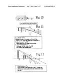
[0090] FIGS. 10-12 illustrate basic optic lens theory, which is applied to the current invention to precisely calculate the optics lens, focus, position of the light source, position of all lenses, position of the slides, and/or telescope length to get a desire image that is as perfect as possible.
[0091] Although preferred embodiments of the invention have been described in detail to show the scope of the current invention, it is to be appreciated that any alternative or equivalent functions, or design, construction, modification, and/or up-grade, may still fall within the scope of the invention, which is not limited by the details mentioned in the above discussion. Any alternative or equivalent arrangement, process, installation or the like may still fall within the scope of the current invention, including alternatives to the power source, conductive means, geometric shape of LED-units, joint-means, circuit means, sensor means, switch means, LED elements, attachment means, fixing-means, tightening means, and/or resilient conductive means, which may all have alternative arrangements, design, and construction.
User Contributions:
Comment about this patent or add new information about this topic:
Images included with this patent application:
 |  |
 |  |
 |  |
 |  |
| Similar patent applications: | |
| Date | Title |
|---|---|
| 2015-12-31 | Laser projection light |
| 2016-02-25 | Flashing night light |
| 2016-03-17 | Directional flashlight |
| 2012-11-01 | Led night-light |
| 2014-06-12 | Led night-light |
| New patent applications in this class: | |
| Date | Title |
|---|---|
| 2015-03-12 | Led projection night light |
| 2015-03-12 | Led plug-in or usb wired light has more than one optics means has reflective or/and refractive properties to create wider viewing angle range image |
| 2015-03-12 | Led light has more than one reflective means to project image |
| 2014-11-06 | System for projecting a simulated liquid surface |
| New patent applications from these inventors: | |
| Date | Title |
|---|---|
| 2022-08-25 | Wired and detachable charging-unit of electric product |
| 2020-08-20 | Quickly charger usb device has separated distance away usb unit(s) |
| 2020-04-16 | Multiple functions led night light |
| 2020-03-19 | Led night light has usb-unit(s) and/or outlet-unit(s) |
| 2020-03-19 | Desk top alarm or time or led lighting device has usb-port(s) |
| Top Inventors for class "Illumination" | |
| Rank | Inventor's name |
|---|---|
| 1 | Shao-Han Chang |
| 2 | Kurt S. Wilcox |
| 3 | Paul Kenneth Pickard |
| 4 | Chih-Ming Lai |
| 5 | Stuart C. Salter |