Patent application title: Orthopedic Implant Kit
Inventors:
Morten Beyer (Rodkaersbro, DK)
IPC8 Class: AA61B1770FI
USPC Class:
606266
Class name: Rod attachable by threaded fastener with head of fastener attachable to longitudinal rod ball and socket type (e.g., polyaxial)
Publication date: 2016-03-31
Patent application number: 20160089186
Abstract:
An orthopedic implant kit comprising a lockable poly-axial screw, a
tissue dilatation sleeve, a screw driver, a screw extender, a rod,
rod-reduction device, a set screw driver, a torque limiting device and a
screw releasing device.Claims:
1. An orthopedic implant kit comprising: a lockable poly-axial screw; a
tissue dilatation sleeve; a screw driver; a screw extender; a rod; a
rod-reduction device; a set screw driver; a torque limiting device
mechanism; and a screw releasing device instrument.
2. A lockable poly-axial orthopedic screw for an implant kit, the implant kit having a tissue dilatation sleeve, a screw driver, a screw extender, a rod, a rod reduction device, a set screw driver, a torque limiting device, and a screw releasing device, the screw comprising, a head and a threaded portion, the head and the threaded portion forming two separate elements that are fixed to each other and are independently orientable along a specific direction; and a locking element that, when locked, suppresses a relative movement between the threaded portion and the head to transform the poly-axial screw into a mono-axial screw.
3. The screw according to claim 2, wherein the locking element includes a clip having a U-shape and at least one of the head and the threaded portion include cavities configured to receive branches of the clip having the U-shape.
4. The screw according to claim 2, further comprising: a head including a longitudinal groove or a longitudinal ridge, the longitudinal groove or longitudinal ridge being configured to receive a corresponding longitudinal ridge or a corresponding longitudinal groove, respectively, that is located within the distal end of the screw extender.
5. The screw according to claim 2, further comprising: a concave seat located in a proximal end of the threaded portion and a corresponding convex engagement surface located at a distal part of the head.
6. An orthopedic screw extender for an implant kit, the implant kit having a lockable poly-axial screw, a tissue dilatation sleeve, a screw driver, a rod, a rod reduction device, a set screw driver, a torque limiting device, and a screw releasing device, the screw extender comprising: a hollow cylindrical body made of two half tubes separated by two opposite longitudinal slots having an open end towards a distal part of the hollow cylindrical body, the distal part configured to receive and hold a screw head, the hollow cylindrical body including an internal threaded part.
7. The screw extender according to claim 6, wherein the hollow cylindrical body is made of a single element and the distal part is made of an elastic material such that the distal part is radially expandable to allow a clipping and subsequent releasing of the head of the lockable poly-axial screw.
8. The screw extender according to claim 6, further comprising: an internal tube adapted to radially expand the distal part.
9. The screw extender according to claim 6, wherein an internal part of the distal part includes a longitudinal ridge or a longitudinal groove dimensioned to receive a corresponding longitudinal groove or longitudinal ridge, respectively of the head of the lockable poly-axial screw.
10. The screw extender according to claim 6, wherein the rod reduction device is located within the cylindrical body.
11. The screw extender according to claim 10, wherein the rod reduction device includes a shaft with a threaded distal part.
12. The screw extender according to claim 6, wherein the set screw driver is located within the hollow cylindrical body.
13. The screw extender according to claim 12, wherein the set screw driver includes a shaft with a threaded distal part.
14. The screw extender according to claim 12, wherein the set screw driver comprises the torque limiting device.
15. The screw extender according to claim 14, wherein the torque limiting device includes a breakable pin and a thread free rotatable shaft, the breakable pin laterally crossing the thread free rotatable shaft.
16. The screw extender according to claim 6, wherein the screw releasing device is located within the cylindrical body.
17. The screw extender according to claim 16, wherein the screw releasing device includes a shaft with a threaded distal part.
18. The screw extender according to claim 17, further comprising: a single shaft with a threaded distal part, the single shaft and the threaded distal part forming elements of the rod reduction device, the set screw driver, and the screw releasing device.
19. A tissue dilatation sleeve comprising a flexible conical part which is adapted to be temporarily fixed to a distal part of a screw extender including a hollow cylindrical body made of two half tubes separated by two opposite longitudinal slots having an open end towards the distal part of the hollow cylindrical body, the hollow cylindrical body including an internal threaded part.
20. The tissue dilatation sleeve according to claim 19, wherein the conical part is made of a plurality of longitudinal flexible blades having each a substantially triangular shape.
Description:
FIELD OF INVENTION
[0001] The present invention relates to orthopedics and more precisely to orthopedic items such as pedicle screws, rods and spine cages. The invention also relates to instruments which are used for manipulating those items.
BACKGROUND
[0002] US 2013/0012999 discloses an orthopedic implant kit comprising several items, in particular a pedicle screw fixed to a mounting tube made of two half-shells which can be easily disassembled.
[0003] Pedicle screws of the prior art can be divided in two main groups:
[0004] Mono-axial screws: The direction of the screw main axis is fixed with respect the screw head;
[0005] Poly-axial screws: The orientation of the screw main axis can be freely modified with respect to the screw head.
[0006] When implanting a pedicle screw into a bone several steps are needed. For almost each of those steps a dedicated instrument is used.
GENERAL DESCRIPTION OF THE INVENTION
[0007] An objective of the present invention is to reduce the number of items which are required for manipulating and fixing an orthopedic implant (pedicle screw, nut, rod, etc. . . . ).
[0008] Another objective is to reduce the number of instruments for manipulating those items.
[0009] Another objective is to facilitate the handling of the instruments.
[0010] Those objectives are met with the implant kit and the related items and instruments which are defined in the claims.
[0011] In a first embodiment the invention consists in an orthopedic implant kit comprising a lockable poly-axial screw, a tissue dilatation sleeve, a screw driver, a screw extender, a rod, rod-reduction means, a set screw driver, a torque limiting mechanism and a screw releasing instrument.
[0012] The lockable poly-axial orthopedic screw according to the invention comprises a head and a threaded portion which form two separate elements, fixed to each other but each element may be independently oriented along a specific direction. The threaded portion may, for instance, rotates around the screw head and may adopt several possible orientations. More precisely, the threaded portion may be oriented anywhere within a conical volume, the top of the cone corresponding to the contact point between the head and the threaded portion.
[0013] The screw furthermore comprises a locking element which, when activated, suppresses the relative movement between the threaded portion and the head. This configuration is named "mono-axial" because the threaded portion may be oriented along a single (fixed) axis with respect to the head.
[0014] According one embodiment the locking element is a clip having a U-shape. In this case the head and the threaded portion contains cavities which are adapted to receive the branches of the U-shape clip.
[0015] Preferably, in the mono-axial mode the head may still freely rotate around its own axis, with respect to the threaded portion. Such a mechanism may be obtained with a U-shape clip and with an annular groove located around the upper part of the threaded portion. In this case the branches of the clip are sliding within the annular groove.
[0016] In another embodiment the screw head contains at least one longitudinal relief, such as a groove or a ridge, which is dimensioned in a way as to receive a corresponding relief, such as a ridge or a groove, which is located within the distal end of a screw extender.
[0017] In another embodiment the screw comprises a concave seat located in the proximal end of the threaded portion and a corresponding convex shape located at the distal part of the screw head. This configuration reduces the screw length and increases the strength and the rigidity of the system.
[0018] The screw extender according to the invention comprises a hollow cylindrical body made of two half tubes separated by two opposite longitudinal slots having an open end towards the cylindrical body distal part, this later one being dimensioned to receive and hold a screw head. The cylindrical body furthermore comprises an internal threaded part.
[0019] According to one embodiment the cylindrical body is made of a single piece and the distal part is radially expandable by its own elasticity, in such a way as to allow an easy clipping and subsequent releasing of a screw head.
[0020] To facilitate its radial expansion, the screw extender may include expanding means, for instance an internal rotatable tube which, when rotated pushes away the two half tubes from each other.
[0021] In a preferred embodiment the internal part of the cylindrical body distal end contains at least one relief, such as a ridge or a groove, which is dimensioned to be received within the longitudinal relief of a screw head which includes a corresponding relief, as mentioned previously. With this configuration it hinders the distal part of the half tubes to separate from each other by its own elasticity thus making a very strong attachment between the screw extender and the screw head. An additional benefit is that the relative rotation between the screw head and the cylindrical body is avoided.
[0022] In a preferred embodiment a rod reduction instrument is located within the cylindrical body. Advantageously the rod reduction instrument is essentially made of a shaft with a threaded distal part which is the counterpart of the cylindrical body internal threaded part. So when it is rotated within the cylindrical body the shaft may move along the cylindrical body main axis.
[0023] In another embodiment a set screw driver is (also or alternatively) located within said cylindrical body. In this case also, the set screw driver may also essentially be made of a shaft with a threaded distal part.
[0024] Advantageously the set screw driver comprises a torque limiting mechanism.
[0025] In one embodiment this mechanism includes a breakable pin and a thread free rotatable shaft. The pin is laterally crossing the rotatable shaft and its ends are fixed within the threaded rotatable shaft.
[0026] The threaded and the threaded free shafts are rotatably linked to each other but when a certain torque is reached the pin breaks and each shaft may freely rotates with respect to the other shaft.
[0027] In another embodiment a screw releasing instrument is (also or alternatively) located within said cylindrical body.
[0028] Advantageously the screw releasing instrument is essentially made of a shaft with a threaded distal part.
[0029] In a particularly interesting embodiment, the same shaft with a threaded distal part is used for the rod reduction instrument (and potential sponylolisthesis), the set screw driver and the screw releasing mechanism.
[0030] The tissue dilatation sleeve according to the invention comprises a flexible conical part which is adapted to be temporarily fixed to the distal part of an instrument such as a screw extender as defined in the previous claims.
[0031] In one embodiment the conical part is made of several longitudinal flexible blades having each a substantially triangular shape.
DETAILED DESCRIPTION OF THE INVENTION
[0032] The invention will be better understood in the following part of this document, with non-limiting examples illustrated by the following figures:
[0033] FIG. 1 shows an implant kit according to the invention
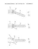
[0034] FIG. 2 shows an example of a lockable poly-axial pedicle screw according to the invention
[0035] FIGS. 3A to 3C are cross-sections and partial cut views of the screw of FIG. 2
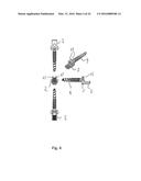
[0036] FIG. 4 represents different views (complete and partial) of the screw of FIG. 2
[0037] FIG. 5 shows the distal part of a screw extender according to the invention, together with the screw of FIG. 2
[0038] FIG. 6 is a cross section of the screw extender distal part
[0039] FIG. 7 is a global view of a screw extender with a screw
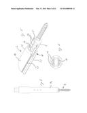
[0040] FIGS. 8A to 8C represent the positioning of the rod in the screw head, rod reduction and the tightening of the set screw
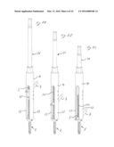
[0041] FIGS. 9A to 9C illustrate the release of the screw with respect to the screw extender
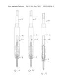
[0042] FIG. 10 shows a screw extender which includes a mechanism for laterally expanding the screw extender distal part
[0043] FIG. 11 is another representation of the screw extender of FIG. 10
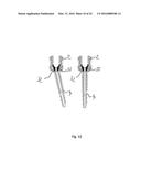
[0044] FIG. 12 shows another embodiment of a pedicle screw according to the invention
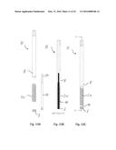
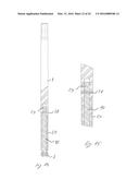
[0045] FIGS. 13A to 13C show different views of a rotatable shaft which is used in a rod reduction instrument, a set screw driver and a screw releasing instrument
[0046] FIGS. 14 and 15 illustrate a torque limiting mechanism
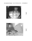
[0047] FIGS. 16 and 17 show the use of a tissue dilatation sleeve
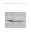
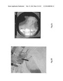
[0048] FIGS. 18 to 38 show a procedure using an implant kit according to the invention
NUMERICAL REFERENCES USED IN THE FIGURES
TABLE-US-00001
[0049] 1. Pedicle screw 2. Head 3. Set screw 4. Threaded portion 5. Locking element 6. Screw extender 7. Rod 8. Multi-use instrument upper part 9. Tissue dilatation sleeve 10. Torque driver 11. Head passage 12. Threaded portion passage 13. Branch 14. Cylindrical body 15. Slot 16. Cylindrical body distal part 17. Ridge 18. Groove 19. Screw extender internal threaded part 20. Multi-use instrument lower part 21. Conical part 22. Blade 23. Half tube 24. Screw driver 25. Handle 26. Multi-use instrument (Rod reduction/Set screw driver/screw release) 27. Rod inserting instrument 28. Breakable pin 29. Lateral pin 30. Circular groove 31. Puncturing needle/Guide wire 32. Concave screw top 33. Convex upper half ball
[0050] The examples below more precisely relate to a thoracolumbar fusion system consisting of pedicle screws and rods combined with single use instruments. A typical pedicle screw system consists of the screw implants and the instruments for placing the screws.
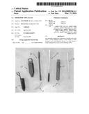
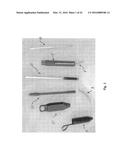
[0051] FIG. 1 shows an example of an implant kit according to the invention.
[0052] This kit contains a tissue dilatation sleeve 9, a handle 25, a rod 7, a rod inserting instrument 27, a shaft 26 which can be used as a rod reduction instrument and/or a set screw driver and/or a screw releasing instrument, a pedicle screw 1, a screw extender 6 and a screw driver 24.
[0053] The lockable poly-axial screw 1 illustrated in particular in FIGS. 2 to 4 includes a head 2 and a threaded portion 4. FIG. 2 also shows a set screw 3 which may be fixed to the head after the insertion of a rod 7. The screw 1 furthermore comprises a locking element 5 having a U-shape. When the locking element 5 is fully inserted in the screw head 2 the orientation of threaded portion 4 is blocked with respect to the head 2. Inversely, when the locking element is retrieved, the threaded portion 4 can be freely oriented with respect to the screw head 2.
[0054] The lockable poly-axial screw according to the invention may therefore be transformed into a mono-axial screw, thus allowing having mono-axial and poly-axial capability in the same product. A blocking system defined previously allows the surgeon to choose if he/she wants to use the screw in mono-axial or poly-axial mode. As mentioned mono-axial capability is achieved by pushing the locking element (clip) 5 and poly-axial capability is achieved by removing the clip 5. The clip 5 is just an example of a blocking system; other technical solutions can also be imagined such as a pin.
[0055] Preferably, in the mono-axial mode the head may still freely rotate around its own axis, with respect to the threaded portion. Such a mechanism may be obtained with a U-shape clip and with an annular groove located around the upper part of the threaded portion. In this case the branches of the clip are sliding within the annular groove.
[0056] Any orientation of the axis can be considered when the mono-axial is used, i.e. the screw axis and the screw head may be oriented along different directions.
[0057] FIGS. 5 to 7 represent the attachment of a pedicle screw 1 to the distal end 16 of a screw extender 6, by inserting the screw head 2 within the distal end 16. In this operation the head 2 is guided with a plurality of ridges 17 located within the distal end 16 and grooves located on the head 2. With such a system the screw head is better retained within the screw extender 6.
[0058] Any suitable material can be used for the screw extender 6 (plastic, polymer, metal, etc. . . . ).
[0059] FIGS. 8A to 8C represent the positioning of the rod 7 in the screw head 2, a rod reduction and the tightening of the set screw 3 in the screw head 2.
[0060] The multi-use instrument 26 (see also FIGS. 13A to 13B) is defined by an upper part 8 and a lower (threaded) part 20.
[0061] The rod 7 may be pushed downwards by rotating the multi-use instrument 26 within the cylindrical body 14.
[0062] After the rod insertion within the head 2, the set screw 3 is fixed to the head 2 by further rotating the multi-use instrument 26.
[0063] The multi-use instrument 26 is also provided with a torque limiting mechanism (see FIGS. 14 and 15). When the set screw 3 is fixed within the head 2 and the multi-use instrument 26 further rotated, the torque increases, up to a point where the pin 28 breaks. A further rotation of the multi-use instrument 26 has therefore no more effect on the set screw 3. From that point the further rotation of the multi-use instrument 26 only induces a downwards pressure on the screw head 2. The screw 1 is therefore progressively separated from the screw extender (see FIGS. 9A to 9C).
[0064] This screw releasing mechanism from an instrument offers the possibility to release the screw 1 from the screw extender without laterally expanding the screw extender 6.
[0065] It should be mentioned at this stage that this mechanism is not limited to the release of pedicle screws. Any other item may be used.
[0066] To summarize, the same instrument 26 can be used for rod reduction, for fixing a set screw to a screw head and for releasing a screw from a screw extender.
[0067] It should be underlined that the invention is not limited to this triple use of the same instrument. A double use is also comprised, for instance rod-reduction and fixation of the screw set to the screw head.
[0068] FIGS. 10 and 11 show an alternative solution to attach a pedicle screw to an screw extender, by rotating an inside tube (not illustrated) the half-tubes 23 are expanded by their own elasticity. This allows a screw to be inserted and fixed to it by for example clamping the outer surface around the screw. The same principle can be used as an alternative to detach the screw extender from a screw.
[0069] The clamping system also achieves part of its rigidity, by resting on support surfaces on the screw head.
[0070] FIG. 12 shows a concave screw top 32, inside a convex upper half ball 33, allowing the rod 7 and the set screw 3 to be set lower in the screw head 2, thus decreasing the total build height, and increasing the strength and rigidity of the system.
[0071] FIGS. 16 and 17 represents a tissue dilatation sleeve 9 containing four triangular flexible blades 22 intervened into each other and forming a cone 21. The cone 21 is mounted at the tip of a screw extender 6, with a tear off spiral. This allows the tissue to be pushed aside as the screw extender 6 is inserted into a body. Once in place, the surgeon may remove the sleeve 9 while the screw extender remains in the body. Any suitable number of blades can be used for forming the cone.
[0072] FIGS. 18 to 38 show a procedure using the items which have been previously presented.
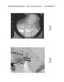
[0073] In a first step (FIGS. 18 and 19) two puncturing guide wires 31 are positioned in the spine.
[0074] A first screw extender 6 with a screw 1 attached and surrounded by a dilatation sleeve is then inserted through the tissue (FIGS. 20 and 21), and along the guide wire 31. The screw extender 6 is rotated and/or pushed.
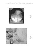
[0075] A similar operation is carried out with a second screw extender 6 and screw 1 (FIGS. 22 and 23).
[0076] A screw driver 24 is inserted within the screw extender 6. Its distal end is introduced within the upper part of the screw threaded portion 4. The screws 1 are then rotated and enter the vertebrae (FIGS. 24 and 25).
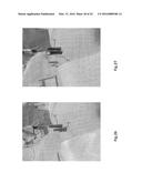
[0077] The tissue dilatation sleeves 9 are removed (FIGS. 26 to 28).
[0078] A rod inserting instrument 27 with a rod 7 at its end is transversally crossing the tissue (FIGS. 29 and 30).
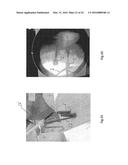
[0079] The rod 7 is positioned above the screw head 2 (FIG. 32) and the multi-use instrument 26 is introduced within the screw extender 6, to such an extent that the set screw 3 is positioned above the rod 7, in line with the screw head 2 (FIGS. 31 and 32).
[0080] FIGS. 33 to 36 show the rod placement within the screw heads 2 and the fixation of the set screw 3 within the screw head 2.
[0081] FIGS. 37 and 38 illustrate the screw release from the screw extender 6 and the screw 1, the rod 7 and the screw set 3 in their definitive location.
[0082] The invention is of course not limited to those illustrated examples.
[0083] The screw extender according to the invention may be used with mono-axial, poly-axial or lockable poly-axial screws.
User Contributions:
Comment about this patent or add new information about this topic:
Images included with this patent application:
 |  |
 |  |
 |  |
 |  |
 |  |
 |  |
 |  |
 |  |
 |  |
 |  |
 |  |
 |  |
 |
| Similar patent applications: | |
| Date | Title |
|---|---|
| 2016-04-14 | Orthopaedic impactor with radially expanding threading |
| 2016-04-21 | Orthopedic tools for implantation |
| 2016-01-28 | Orthopedic plate blocking assembly |
| 2016-04-07 | Cement-directing orthopedic implants |
| 2016-05-12 | Variable axis locking mechanism for use in orthopedic implants |
| New patent applications in this class: | |
| Date | Title |
|---|---|
| 2019-05-16 | Medical instrument for provisionally fastening a polyaxial pedicle screw |
| 2018-01-25 | Spinal implant system and methods of use |
| 2018-01-25 | Cannulated polyaxial screw |
| 2017-08-17 | Anchoring member suitable for use in a polyaxial bone anchoring device and polyaxial bone anchoring device with an enlarged pivot angle to one side |
| 2016-12-29 | Polyaxial bone screw |
| Top Inventors for class "Surgery" | |
| Rank | Inventor's name |
|---|---|
| 1 | Lutz Biedermann |
| 2 | Roger P. Jackson |
| 3 | Wilfried Matthis |
| 4 | Frederick E. Shelton, Iv |
| 5 | Joseph D. Brannan |