Patent application title: BEVERAGE CONTAINER FOR CHILD
Inventors:
Joung-Suk Kim (Hwaseong-Si, Gyeonggi-Do, KR)
IPC8 Class: AB65D5100FI
USPC Class:
220265
Class name: Closures with closure opening arrangements for means (e.g., opening devices) frangible member or portion
Publication date: 2016-03-24
Patent application number: 20160083154
Abstract:
A beverage container for a child includes a container for containing
beverages and a lid for opening/closing the upper portion of the
container. The lid includes a body which is coupled to the upper portion
of the container and blocks the inner space of the container from the
outside. The lid also includes a straw holding part in which a straw is
held, the straw holding part being coupled to the body of the lid. A
fixing part is coupled to the body at the lower side of the straw holding
part to fix the straw holding part to the body.Claims:
1. A beverage receptacle for a baby comprising: a receptacle body into
which a beverage is contained; and a lid adapted to open/close the
receptacle body and having a lid body adapted to be coupled to the upper
end periphery of the receptacle body in such a manner as to allow the
internal space of the receptacle body to be blocked from the outside and
a straw insertion part adapted to be coupled to the lid body, through
which a straw is insertedly passed.
2. The beverage receptacle for a baby according to claim 1, wherein the lid further comprises a fixing part disposed on the underside of the straw insertion part in such a manner as to be coupled to the lid body, for fixing the straw insertion part to the lid body.
3. The beverage receptacle for a baby according to claim 1, wherein the lid body has a first through hole formed passed up and down therethrough, a mounting portion extended downward therefrom around the first through hole, and a locking projection 126 protrudedly formed inward along the lower portion of the inner peripheral surface of the mounting portion, and the straw insertion part is forcedly fitted to the locking projection of the mounting portion of the lid body.
4. The beverage receptacle for a baby according to claim 2, wherein the lid body has a first through hole formed passed up and down theretrough, a mounting portion extended downward therefrom around the first through hole, and a fixing groove formed inward along the upper portion of the outer peripheral surface of the mounting portion, and the fixing part has a third through hole formed on the bottom surface thereof to surround the outer peripheral surface of the mounting portion in such a manner as to pass the straw therethrough and a fixing projection protrudedly formed inward along the upper portion of the inner peripheral surface thereof in such a manner as to be coupled to the fixing groove of the mounting portion.
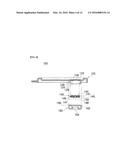
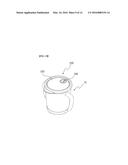
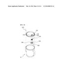
5. The beverage receptacle for a baby according to claim 1, wherein the straw insertion part comprises a first disc and a second disc, and the first disc has a soft blocking film formed in the middle portion thereof, the blocking film having an incised portion formed to pass the straw therethrough, while the second disc having a second through hole formed at the center thereof.
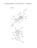
6. The beverage receptacle for a baby according to claim 1, wherein the straw insertion part comprises: a first disc having a second through hole formed at the center thereof, through which the straw is passed, and a flexible portion formed around the second through hole and having a given expansion force; and a second disc adapted to be laid on the first disc and having a seal formed in the middle thereof and an incised portion formed on the seal, the seal having a given expansion force so that when the straw is passed through the incised portion of the seal, the seal comes into contact with the outer peripheral surface of the straw.
7. The beverage receptacle for a baby according to claim 5 or 6, wherein the first disc and the second disc are located on both sides of a connection portion in such a manner as to be folded as a unitary body to each other around the connection portion.
8. The beverage receptacle for a baby according to claim 5 or 6, wherein the first disc has at least one or more pores formed thereon, through which air is passed from the outside of the receptacle body to the inside of the receptacle body.
9. The beverage receptacle for a baby according to claim 8, wherein each pore has a shape of a cone having the upper portion having a larger diameter than the lower portion thereof.
10. The beverage receptacle for a baby according to claim 6, wherein the first disc has a first stepped projection formed along the lower end periphery thereof to allow the outer peripheries of the first disc and the second disc to be sealed to form a space on the center portions of the first disc and the second disc.
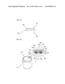
11. The beverage receptacle for a baby according to claim 10, wherein the second disc has a second protruding portion formed spaced apart from the outer peripheral surface thereof by a width of the first stepped projection to allow the outer peripheries of the first disc and the second disc to be sealed to form a space on the center portions of the first disc and the second disc.
12. The beverage receptacle for a baby according to claim 10, wherein the second disc has an arch-shaped protruding portion extended from the second protruding portion in such a manner as to surround half of the outer periphery of the pore.
13. The beverage receptacle for a baby according to claim 6, wherein the first disc has a first protruding portion formed on the top surface thereof.
14. The beverage receptacle for a baby according to claim 6, wherein the second disc has a second stepped projection formed on the underside end periphery thereof.
Description:
TECHNICAL FIELD
[0001] The present invention relates to a beverage receptacle for a baby, and more particularly, to a beverage receptacle for a baby that is capable of allowing a beverage such as water, milk, juice and the like contained therein to be safely sucked through a straw, without having any leakage to the outside.
BACKGROUND ART
[0002] Generally, babies cannot be freely moved because they are not developed physically. If a beverage such as water, milk, juice and the like contained in a cup or the like is provided to the babies, they almost spill the beverage, thus making their clothes or the surrounding environment stained.
[0003] So as to solve the above-mentioned problems, Korean Utility Model Registration No. 20-0466728 entitled `multi-purpose cup for baby` has been disclosed wherein a trumpet-shaped stopper is formed on a lid part and a covering is disposed on the hole of the trumpet-shaped stopper, thus preventing the beverage contained in the cup from spilling to the outside.
[0004] Further, there has been proposed Korean Patent Laid-Open Application No. 2001-0016126 entitled `straw and airtight beverage receptacle having the straw` wherein a straw is fixedly folded after the beverage in the receptacle has been sucked by a desired amount through the straw, so that the beverage remaining in the receptacle can be kept in airtight state.
[0005] Furthermore, there has been proposed Korean Utility Model Registration No. 20-0129032 entitled `baby cup` wherein a straw inserted into a discharge hole is always kept engaged at the top end thereof with an annular protrusion formed along the inner peripheral surface of an auxiliary stopper, and an annular protrusion formed along the outer peripheral surface of the auxiliary stopper comes into close contact with the outer peripheral surface of the discharge hole being contacted therewith, thus maintaining the airtight state and preventing the beverage from leaking through the discharge hole.
[0006] According to the conventional practice, on the other hand, a receptacle to which a lid is attached has a relatively large opening, and accordingly, if the beverage is sucked without having any straw, the beverage almost spills. Even if the beverage is sucked through the straw, it may leak to the outside through the gap formed around the portion where the straw is inserted.
DISCLOSURE
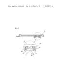
Technical Problem
[0007] Accordingly, the present invention has been made in view of the above-mentioned problems occurring in the prior art, and it is an object of the present invention to provide a beverage receptacle for a baby that is capable of preventing a beverage contained in a receptacle body from leaking to the outside, while the beverage is being sucked.
[0008] It is another object of the present invention to provide a beverage receptacle for a baby that is capable of sucking the beverage contained in a receptacle body through various kinds of straws.
[0009] It is still another object of the present invention to provide a beverage receptacle for a baby that is capable of separating their parts from each other for their washing.
[0010] It is yet another object of the present invention to provide a beverage receptacle for a baby that is capable of maintaining a clean sanitary state even after the repeated use for a long period of time.
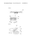
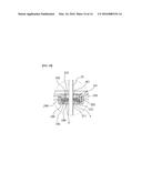
Technical Solution
[0011] To accomplish the above-mentioned objects, according to the present invention, there is provided a beverage receptacle for a baby including: a receptacle body into which a beverage is contained; and a lid adapted to open/close the receptacle body and having a lid body adapted to be coupled to the upper end periphery of the receptacle body in such a manner as to allow the internal space of the receptacle body to be blocked from the outside and a straw insertion part adapted to be coupled to the lid body, through which a straw is insertedly passed.
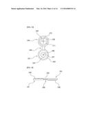
[0012] According to the present invention, desirably, the lid further includes a fixing part disposed on the underside of the straw insertion part in such a manner as to be coupled to the lid body, for fixing the straw insertion part to the lid body.
[0013] According to the present invention, desirably, the lid body has a first through hole formed passed up and down theretrough, a mounting portion extended downward therefrom around the first through hole, and a locking projection protrudedly formed inward along the lower portion of the inner peripheral surface of the mounting portion, and the straw insertion part is forcedly fitted to the locking projection of the mounting portion of the lid body.
[0014] According to the present invention, desirably, the lid body has a first through hole formed passed up and down therethrough, a mounting portion extended downward therefrom around the first through hole, and a fixing groove formed inward along the upper portion of the outer peripheral surface of the mounting portion, and the fixing part has a third through hole formed on the bottom surface thereof to surround the outer peripheral surface of the mounting portion in such a manner as to pass the straw therethrough and a fixing projection protrudedly formed inward along the upper portion of the inner peripheral surface thereof in such a manner as to be coupled to the fixing groove of the mounting portion.
[0015] According to the present invention, desirably, the straw insertion part includes a first disc and a second disc, and the first disc has a soft blocking film formed in the middle portion thereof, the blocking film having an incised portion formed to pass the straw therethrough, while the second disc having a second through hole formed at the center thereof.
[0016] According to the present invention, desirably, the straw insertion part includes: a first disc having a second through hole formed at the center thereof, through which the straw is passed, and a flexible portion formed around the second through hole and having a given expansion force; and a second disc adapted to be laid on the first disc and having a seal formed in the middle thereof and an incised portion formed on the seal, the seal having a given expansion force so that when the straw is passed through the incised portion of the seal, the seal comes into contact with the outer peripheral surface of the straw.
[0017] According to the present invention, desirably, the first disc and the second disc are located on both sides of a connection portion in such a manner as to be folded as a unitary body to each other around the connection portion.
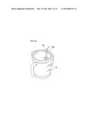
[0018] According to the present invention, desirably, the first disc has at least one or more pores formed thereon, through which air is passed from the outside of the receptacle body to the inside of the receptacle body.
[0019] According to the present invention, desirably, each pore has a shape of a cone having the upper portion having a larger diameter than the lower portion thereof.
[0020] According to the present invention, desirably, the first disc has a first stepped projection formed along the lower end periphery thereof to allow the outer peripheries of the first disc and the second disc to be sealed to form a space on the center portions of the first disc and the second disc.
[0021] According to the present invention, desirably, the second disc has a second protruding portion formed spaced apart from the outer peripheral surface thereof by a width of the first stepped projection to allow the outer peripheries of the first disc and the second disc to be sealed to form a space on the center portions of the first disc and the second disc.
[0022] According to the present invention, desirably, the second disc has an arch-shaped protruding portion extended from the second protruding portion in such a manner as to surround half of the outer periphery of the pore.
[0023] According to the present invention, desirably, the first disc has a first protruding portion formed on the top surface thereof.
[0024] According to the present invention, desirably, the second disc has a second stepped projection formed on the underside end periphery thereof.
Advantageous Effect
[0025] According to the first and second embodiments of the present invention, as mentioned above, the beverage receptacle for a baby includes the lid body, the straw insertion part and the fixing part disposed on the lid of the receptacle body, so that while the beverage contained in the receptacle body is being sucked through the straw, it does not leak to the outside.
[0026] In addition, the beverage contained in the receptacle body can be sucked through various kinds of straws, and the parts of the beverage receptacle can be separated from each other for their washing, thus maintaining a clean sanitary state even after the repeated use for a long period of time.
BRIEF DESCRIPTION OF THE DRAWINGS
[0027] The above and other objects, features and advantages of the present invention will be apparent from the following detailed description of the preferred embodiments of the invention in conjunction with the accompanying drawings, in which:
[0028] FIG. 1 is a perspective view showing a beverage receptacle for a baby according to a first embodiment of the present invention;
[0029] FIG. 2 is a separate perspective view showing the beverage receptacle for a baby of FIG. 1;
[0030] FIG. 3 is a separate perspective view showing a lid in the beverage receptacle for a baby according to the first embodiment of the present invention;
[0031] FIG. 4 is a separate sectional view showing the lid in the beverage receptacle for a baby according to the first embodiment of the present invention;
[0032] FIGS. 5 to 6 are sectional and partially enlarged views showing the lid in the beverage receptacle for a baby according to the first embodiment of the present invention;
[0033] FIG. 7 is an enlarged perspective view showing a straw insertion part in the beverage receptacle for a baby according to the first embodiment of the present invention;
[0034] FIG. 8 is a perspective view showing the beverage receptacle for a baby according to the first embodiment of the present invention into which a straw is inserted;
[0035] FIG. 9 is a partially enlarged sectional view showing the beverage receptacle for a baby according to the first embodiment of the present invention into which a straw is inserted;
[0036] FIG. 10 is a perspective view showing a beverage receptacle for a baby according to a second embodiment of the present invention;
[0037] FIG. 11 is an enlarged perspective view showing a straw insertion part in the beverage receptacle for a baby according to the second embodiment of the present invention;
[0038] FIG. 12 is an enlarged plan view showing the straw insertion part in the beverage receptacle for a baby according to the second embodiment of the present invention;
[0039] FIG. 13 is an enlarged bottom view showing the straw insertion part in the beverage receptacle for a baby according to the second embodiment of the present invention;
[0040] FIG. 14 is a left side view showing the beverage receptacle for a baby according to the second embodiment of the present invention;
[0041] FIG. 15 is a sectional view showing a state where a first disc and a second disc are laid on each other in the beverage receptacle for a baby according to the second embodiment of the present invention;
[0042] FIG. 16 is a partially enlarged sectional view showing the beverage receptacle for a baby according to the second embodiment of the present invention;
[0043] FIG. 17 is a separate perspective view showing the beverage receptacle for a baby according to the second embodiment of the present invention; and
[0044] FIG. 18 is a partially sectional view showing the beverage receptacle for a baby according to the second embodiment of the present invention into which a straw is inserted.
PREFERRED EMBODIMENTS OF THE INVENTION
[0045] Hereinafter, an explanation on a beverage receptacle for a baby according to the present invention will be in detail given with reference to the attached drawing.
[0046] FIGS. 1 to 18 show a beverage receptacle for a baby according to first and second embodiments of the present invention.
[0047] According to the first embodiment of the present invention, a beverage receptacle for a baby having a receptacle body 10 into which a beverage is contained and a lid 100 adapted to open/close the receptacle body 10, wherein the lid 100 includes: a lid body 120 adapted to be coupled to the upper end periphery of the receptacle body 10 in such a manner as to allow the internal space of the receptacle body 10 to be blocked from the outside; a straw insertion part 140 adapted to be coupled to the lid body 120, through which a straw 20 is insertedly passed; and a fixing part 160 disposed on the underside of the straw insertion part 140 in such a manner as to be coupled to the lid body 120, for fixing the straw insertion part 140 to the lid body 120.
[0048] According to the first embodiment of the present invention, as shown in FIGS. 1 to 4, the lid 100 is made by sequentially coupling the lid body 120, the straw insertion part 140 and the fixing part 160 to each other from top to bottom.
[0049] The lid body 120 is a part for almost closing the upper side open portion of the receptacle body 10 and has a first through hole 122 formed passed therethrough and a mounting portion 124 extended downward therefrom around the first through hole 122. The mounting portion 124 is formed to a cylindrical shape on the underside of the lid body 120 and has a larger diameter than the first through hole 122.
[0050] Further, a locking projection 126 is protrudedly formed inward along the lower portion of the inner peripheral surface of the mounting portion 124, and a fixing groove 128 is formed inward along the upper portion of the outer peripheral surface of the mounting portion 124. Accordingly, the straw insertion part 140 is forcedly fitted to the locking projection 126 of the mounting portion 124 and thus located at the inside of the mounting portion 124.
[0051] The fixing part 160 has a generally ``-shaped section and has a third through hole 164 formed on the bottom surface thereof to surround the outer peripheral surface of the mounting portion 124 in such a manner as to pass the straw 20 therethrough and a fixing projection 162 protrudedly formed inward along the upper portion of the inner peripheral surface thereof in such a manner as to be coupled to the fixing groove 128 of the mounting portion 124, so that the fixing part 160 is forcedly fitted to the mounting portion 124.
[0052] That is, the straw insertion part 140 is forcedly fitted to the mounting portion 124, and further, the fixing part 160 fixes the straw insertion part 140 to the mounting portion 124 again, thus preventing the straw insertion part 140 from being escaped from the mounting portion 124.
[0053] Referring to FIG. 4, the straw insertion part 140 includes a first round disc 141 and a second round disc 145. The first disc 141 has a soft blocking film formed in the middle portion thereof and the second disc 145 has a second through hole 148 formed at the center thereof. The blocking film of the first disc 141 has an incised portion 144 formed to pass the straw 20 therethrough. In this case, the incised portion 144 has various shapes capable of passing the straw 20 therethrough, and desirably, two or more incised lines are formed to cross each other.
[0054] The second disc 145 has one or more pores 147 through which air is passed from the outside of the receptacle body 10 to the inside of the receptacle body 10. The pores 147 serve to allow the air at the outside of the receptacle body 10 to enter the inside of the receptacle body 10 when the beverage in the interior of the receptacle body 10 is sucked through the straw 20, thus allowing the beverage to be easily sucked. That is, when the straw 20 is put into the straw insertion part 140, the pores 147 connect the space of the third through hole 164 and the space of the incised portion 144 to each other, thus allowing the air at the outside of the receptacle body 10 to communicate with the air at the inside of the receptacle body 10. Accordingly, each pore 147 desirably has a relatively small diameter in such a manner as to allow air to flow therethrough and to prevent the beverage from being discharged well therethrough to the outside.
[0055] Further, referring to FIG. 7, the first disc 141 and the second disc 145 are located as a unitary body to each other on both sides of a connection portion 149 in such a manner as to be folded to each other around the connection portion 149. Furthermore, referring to FIG. 3, if the first disc 141 and the second disc 145 are formed as the unitary body to each other by means of the connection portion 149, the mounting portion 124 is open at one side thereof, into which the connection portion 149 is mounted.
[0056] Further, it is possible that the first disc 141 and the second disc 145 are located reversely. That is, the first disc 141 is located at the bottom, and the second disc 145 is located on top of the first disc 141.
[0057] Referring to FIGS. 3 to 7, the lid 100 is made by sequentially coupling the lid body 120, the straw insertion part 140 and the fixing part 160 to each other from top to bottom, and the straw 20 is passed through the first through hole 122, the incised portion 144, the second through hole 148 and the third through hole 164, sequentially and then put into the receptacle body 10.
[0058] Further, the lid body 120, the straw insertion part 140 and the fixing part 160 may have accommodating grooves and protrusion portions formed to prevent the occurrence of the movements caused by their coupling. That is, the first disc 141 of the straw insertion part 140 has a first protruding portion 143 formed from the top surface thereof and a second accommodating groove 142 formed on the underside surface thereof, and the second disc 145 has a second protruding portion 146 formed from the top surface thereof in such a manner as to be accommodated into the second accommodating groove 142 and a third accommodating groove 150 formed on the underside surface thereof. Further, the lid body 120 has a first accommodating groove 129 formed on the underside surface thereof (at the interior of the mounting portion 124) in such a manner as to accommodate the first protruding portion 143 thereinto. The fixing part 160 has a third protruding portion 166 extended upward from the third through hole 164 in such a manner as to be accommodated into the third accommodating groove 150.
[0059] Hereinafter, an explanation on a method for using the beverage receptacle for a baby according to the first embodiment of the present invention will be given.
[0060] The beverage contained in the interior of the receptacle body 10 is not primarily discharged to the outside by means of the lid 100 coupled to the open portion of the receptacle body 10. If the straw 20 is not put in the straw insertion part 140, further, the incised portion 144 of the straw insertion part 140 serves to allow the interior of the receptacle body 10 to be blocked from the exterior of the receptacle body 10 and if the straw 20 is put therein, the incised portion 144 becomes bent toward the inside of the receptacle body 10 to surround the straw 20 therearound. At this time, the air at the outside of the receptacle body 10 becomes communicate with the air at the inside of the receptacle body 10 through the pores 147, thus permitting the beverage to be sucked through the straw 20.
[0061] On the other hand, as shown in FIGS. 10 to 18 showing the second embodiment of the present invention, a lid 200 is made by sequentially coupling a lid body 220, a straw insertion part 240 and a fixing part 290 to each other from top to bottom.
[0062] The lid body 120 is a part for almost closing the upper side open portion of the receptacle body 10 and has a first through hole 222 formed passed up and down therethrough. The first through hole 222 has a downward protruding portion 223 extended downward from the underside periphery thereof. The downward protruding portion 223 has a first accommodating groove 229 formed along the outer peripheral surface thereof in such a manner as to fit the straw insertion part 240 as will be discussed later thereinto. A mounting portion 224 is extended downward from the underside of the lid body 220 in such a manner as to be separated from the downward protruding portion 223 by a given distance. The mounting portion 224 is formed to a cylindrical shape on the underside of the lid body 220 and further depressed at one side thereof so as to fit a connection portion 249 as will be discussed later thereinto.
[0063] Further, a locking projection 126 is protrudedly formed inward along the lower portion of the inner peripheral surface of the mounting portion 124, and a fixing groove 128 is formed inward along the upper portion of the outer peripheral surface of the mounting portion 124. Accordingly, the straw insertion part 140 is forcedly fitted to the locking projection 126 of the mounting portion 124 and thus located at the inside of the mounting portion 124.
[0064] The fixing part 290 is coupled to the mounting portion 123 and has a generally ``-shaped section. The fixing part 290 has a third through hole 294 adapted to surround the outer peripheral surface of the mounting portion 224 in such a manner as to pass the straw 20 therethrough and a fixing projection 292 protrudedly formed inward along the upper portion of the inner peripheral surface thereof in such a manner as to be coupled to the fixing groove 228 of the mounting portion 224, so that the fixing part 290 is forcedly fitted to the mounting portion 224. When the mounting portion 224 is coupled to the fixing part 290, the height difference between the inner peripheral surfaces of the mounting portion 224 and the fixing part 290 is similar to the height of the straw insertion part 240, so that the straw insertion part 240 is located at the space between the mounting portion 224 and the fixing part 290 coupled to each other.
[0065] As show in FIGS. 11 to 15, the straw insertion part 240 includes a first disc 241, a second disc 245 and the connection portion 249. The first disc 241 is located up when the straw insertion part 240 is coupled to the lid 200 and made of a soft round disc having a larger diameter than the straw 20. Desirably, the first disc 241 is made of a synthetic resin like silicone having expansion and sealing forces.
[0066] The first disc 241 has a second through hole 248 formed at the center thereof, through which the straw 20 is passed, and the second through hole 248 has a smaller diameter than the straw 20.
[0067] The first disc 241 has a flexible portion 261 formed around the second through hole 248, and the flexible portion 261 is made of an expandable material having a relatively low thickness. As a result, even if the straw 20 is passed through the second through hole 248 having the smaller diameter than the straw 20, the second through hole 248 is extended by means of the expansion of the flexible portion 261, and the flexible portion 261 is bent toward the direction where the straw 20 is put. Accordingly, the flexible portion 261 comes into contact with the outer peripheral surface of the straw 20 and thus seals the space between the straw 20 and the straw insertion part 240.
[0068] The second disc 245 is located down when the straw insertion part 240 is coupled to the lid 200 and made of a soft round disc having an equal diameter to the first disc 241. Like the first disc 241, desirably, the second disc 245 is made of a synthetic resin like silicone having expansion and sealing forces.
[0069] The second disc 245 has a seal 271 formed in the middle thereof, and the seal 271 is made of an expandable material like the flexible portion 261, while having a higher thickness than the flexible portion 261 of the first disc 241. Since the second through hole 248 having the smaller diameter than the straw 20 is formed around the flexible portion 261, the flexible portion 261 needs a higher degree of expansion than the seal 271 so as to pass the straw 20 therethrough.
[0070] The seal 271 has an incised portion 244 formed thereon, and the incised portion 244 is formed up to a length corresponding to the diameter of the straw 20 from the center of the second disc 245. In this case, the incised portion 244 desirably has two or more incised lines formed to cross each other. If the straw 20 is put into the straw insertion part 240, the incised seal 271 is bent gently and comes into contact with the outer peripheral surface of the straw 20.
[0071] When the straw 20 is put into the straw insertion part 240, as mentioned above, it is first passed through the second through hole 248 formed on the first disc 241, thus allowing the outer peripheral surface thereof to be sealed, and after that, the straw 20 is passed through the incised portion 244 formed on the second disc 245, thus reinforcing the sealed state thereof and achieving rigid coupled state. When the straw insertion part 240 is coupled to the lid body 220, accordingly, the beverage does not leak around the straw 20 even after put into the straw insertion part 240. If the entire space of the straw insertion part 240 except the space into which the straw 20 is put is sealed, however, air does not move while the beverage is sucked through the straw 20, so that a difference of atmospheric pressure does not occur, which makes it hard to suck the beverage.
[0072] Accordingly, the first disc 241 has a pore 247 formed thereon, and the pore 247 has a fine diameter, through which air is passed. Accordingly, if the beverage is sucked through the straw 20, air enters the receptacle body 10 through the pore 247 to cause a difference of air pressure, thus allowing the beverage to be easily sucked through the straw 20. As shown in FIG. 16, the pore 247 has a shape of a cone having the upper portion having a larger diameter than the lower portion, which prevents the beverage contained in the receptacle body 10 from leaking through the pore 247, while the air is being sucked through the upper portion of the pore 247.
[0073] Further, the first disc 241 and the second disc 245 are connected to each other by means of the connection portion 249. The connection portion 249 is desirably made of a soft material so as to allow the first disc 241 and the second disc 245 to be laid on each other and coupled to one sides of the first disc 241 and the second disc 245. Further, the connection portion 249 has a groove 250 formed at the center portion thereof so as to be easily folded in half.
[0074] According to the second embodiment of the present invention, so as to prevent the beverage from leaking through the pore 247 and to allow the air to enter the receptacle body 10 when the beverage is sucked through the straw 20, as shown in FIG. 16, the outer peripheries of the first disc 241 and the second disc 245 are sealed when the first disc 241 and the second disc 245 are laid on each other, the center portions of the first disc 241 and the second disc 245 form a space v.
[0075] So as to allow the outer peripheries of the first disc 241 and the second disc 245 to be sealed to form the space v on the center portions of the first disc 241 and the second disc 245, the first disc 241 has a first stepped projection 263 formed along the lower end periphery thereof.
[0076] Further, so as to strengthen the sealing force of the first stepped projection 263, the second disc 245 has a second protruding portion 246 formed spaced apart from the outer peripheral surface thereof by a width of the first stepped projection 263. The first stepped projection 263 and the second protruding portion 246 have rectangular sections, so that the second protruding portion 246 is engagedly coupled to the interior of the first stepped projection 263, thus improving the sealing force.
[0077] The second disc 245 has an arch-shaped protruding portion 275 extended from the second protruding portion 246 on the top surface thereof, and as shown in FIG. 13, the arch-shaped protruding portion 275 is formed to surround half of the outer periphery of the pore 247. As a result, the contacted area between the first disc 241 and the second disc 245 is reduced to prevent the beverage contained in the receptacle body 10 from leaking through the pore 247, while the air is going in and out through the pore 247.
[0078] The first disc 241 has a first protruding portion 243 formed on the top surface thereof, and the first protruding portion 243 serves to allow the straw insertion part 240 to come into contact with the lid 200. For example, as shown in FIG. 16, the first protruding portion 243 is formed spaced apart from the outer periphery of the first disc 241 by a given distance to a shape corresponding to the outer peripheral surface of the first through hole 222 of the receptacle body 10, while having the rectangular section. Further, the shape of the first protruding portion 243 may be freely varied in accordance with the shape of the receptacle body 10.
[0079] The second disc 245 has a second stepped projection 273 formed on the underside end periphery thereof, and in the same manner as the first protruding portion 243, the second stepped projection 273 serves to allow the straw insertion part 240 to come into contact with the lid 200. For example, as shown in FIG. 16, the second stepped projection 273 is formed along the lower end periphery thereof and has the rectangular section in such a manner as to be coupled to the fixing part 290. Further, the shape of the second stepped projection 273 may be freely varied in accordance with the shape of the receptacle body 10.
[0080] According to the second embodiment of the present invention, as mentioned above, even if the straw 20 is put into the straw insertion part 240, as shown in FIG. 13, the outer periphery of the straw 20 is sealed by means of the flexible portion 261 of the first disc 241, and the sealed state is strengthened again by means of the seal 271 of the second disc 245, so that the straw 20 is fixed without any movement. If the beverage is sucked through the straw 20, air goes in and out through the pore 247 formed on the first disc 241 to generate a difference of air pressure, thus making it convenient to suck the beverage. The pore 247 has a fine size and is surrounded partially by the arch-shaped protruding portion 275, so that the beverage contained in the receptacle body 10 does not almost leak to the outside.
[0081] Further, even if the receptacle body 10 is inclined in the state where the straw 20 is put into the straw insertion part 240, the entire portion of the beverage receptacle except the straw 20 becomes water-tight, thus preventing the beverage from leaking to the outside, and moreover, air pressure is generated inside the straw 20, thus preventing the leakage of the beverage through the straw 20.
[0082] According to the first and second embodiments of the present invention, as mentioned above, the beverage receptacle for a baby includes the lid body, the straw insertion part and the fixing part disposed on the lid of the receptacle body, so that while the beverage contained in the receptacle body is being sucked through the straw, it does not leak to the outside.
[0083] In addition, the beverage contained in the receptacle body can be sucked through various kinds of straws, and the parts of the beverage receptacle can be separated from each other for their washing, thus maintaining a clean sanitary state even after the repeated use for a long period of time.
[0084] While the present invention has been described with reference to the particular illustrative embodiments, it is not to be restricted by the embodiments but only by the appended claims. It is to be appreciated that those skilled in the art can change or modify the embodiments without departing from the scope and spirit of the present invention.
User Contributions:
Comment about this patent or add new information about this topic:
Images included with this patent application:
 |  |
 |  |
 |  |
 |  |
 |  |
 |  |
 |  |
 |
| Similar patent applications: | |
| Date | Title |
|---|---|
| 2015-12-24 | Beverage containers |
| 2016-05-05 | Beverage container |
| 2016-04-21 | Liftable container holder |
| 2016-01-28 | Beverage can closing member |
| 2016-02-11 | Beverage cooling device |
| New patent applications in this class: | |
| Date | Title |
|---|---|
| 2016-06-30 | Container with opening recognizable function |
| 2015-12-10 | Rupturable container having directional burst seal |
| 2015-12-03 | Closure with tamper evident secondary piece |
| 2015-12-03 | Penetrable plastics material seal for sealing containers |
| 2015-11-19 | Fluid container ship cap |
| Top Inventors for class "Receptacles" | |
| Rank | Inventor's name |
|---|---|
| 1 | Daniel Lee Bizzell |
| 2 | Frank Yang |
| 3 | Terry Vovan |
| 4 | William P. Apps |
| 5 | Lowell L. Wood, Jr. |