Patent application title: ELETROPLATING APPARATUS FOR PREVENTING EXCESSIVE PLATING OF EDGE
Inventors:
Young Ha Kim (Gwangyang-Si, Jeollanam-Do, KR)
Hwon Woo Jeong (Gwangyang-Si, Jeollanam-Do, KR)
Yong Sik Kang (Gwangyang-Si, Jeollanam-Do, KR)
Assignees:
POSCO
IPC8 Class: AC25D1700FI
USPC Class:
204242
Class name: Apparatus electrolytic cells
Publication date: 2016-03-17
Patent application number: 20160076166
Abstract:
An electroplating device for preventing the excessive plating of an edge,
and the electroplating device for plating a steel plate between anodes
which are formed at a predetermined distance from each other with respect
to the center of the steel plate. A cathode edge mask is provided in the
proximity of the edge part of a steel plate and blocking the edge part
and an anode from being applied with an electric current. Anode edge
masks rare respectively provided to the upper and lower portions of the
cathode edge mask at a distance from each other and blocking the edge
part and anodes from being applied with an electric current.Claims:
1. An electroplating apparatus for plating a steel plate between anodes
disposed on both sides of the steel plate at a predetermined distance
from each other, the electroplating apparatus comprising: a cathode edge
mask disposed adjacent to an edge portion of the steel plate to prevent
the edge portion from being electrically connected to a corresponding
anode of the anodes; and anode edge masks disposed above and below the
cathode edge mask and spaced apart from the cathode edge mask, the anode
edge masks preventing the edge portion from being electrically connected
to the corresponding anode, whereby the edge portion is prevented from
being over-plated.
2. The electroplating apparatus according to claim 1, wherein the anode edge mask is able to increase or decrease an area by which the edge portion is prevented from being electrically connected to the corresponding anode depending on a position where the anode edge mask is coupled.
3. The electroplating apparatus according to claim 2, further comprising: a support connected to one surface of the cathode edge mask; connecting portions extending in a top-bottom direction of the support and coupled with the support and the anode edge masks; a mask driving unit coupled with one end of the support to move the cathode edge mask forward and backward; and two or more positioning holes formed in each of the anode edge masks in a direction toward the steel plate, wherein the connecting portions are fitted into the positioning holes.
4. The electroplating apparatus according to claim 1, wherein the cathode edge mask has a recess formed in a surface that faces the steel plate, the recess allowing the steel plate to pass through.
5. The electroplating apparatus according to claim 4, wherein the recess is inclined to spread in a direction toward the steel plate.
6. The electroplating apparatus according to claim 1, wherein each of the cathode edge mask and the anode edge masks is formed of an insulating material.
7. The electroplating apparatus according to claim 1, wherein the anode edge masks are formed of a conductive material, and have an insulating layer on surfaces facing the anodes.
Description:
TECHNICAL FIELD
[0001] The present invention relates to an electroplating apparatus. More particularly, the present invention relates to an electroplating apparatus able to prevent the edge portions of a steel plate from being over-plated.
BACKGROUND ART
[0002] Generally, steel plates for vehicles or steel plates used for exterior materials of electrical appliances are subjected to electro-galvanization in order to have corrosion resistance required for the purpose of use after annealing.
[0003] In general, during electroplating, an electric current is concentrated at the edge portions of a steel plate. This phenomenon leads to plating defects, since a greater amount of plating metal is attached to the edge portions than the other portions, or dendritic zinc growth occurs on the edge portions. In plating equipment using insoluble anodes, at the portion of the plating equipment, the width of which is greater than the width of the steel plate, the anodes face each other. A difference in the potential between the anodes at that portion is induced by a variety of reasons. This consequently causes the problem in that an iridium oxide film on the anode surface is destroyed, thereby reducing the lifespan of the anodes.
[0004] Describing in more detail, when continuous electroplating is carried out on a steel plate, an electric current is concentrated on the edge portions due to the characteristics of electricity. This leads to the following two problems.
[0005] The first problem is that the edge portions are over-plated, i.e. the edge portions are plated with a greater amount of plating metal than the other portions. In the process of slipping the plated steel plate into a coil, the over-plated edge portions cause bending of the steel plate. Consequently, the coil must be manufactured in a small size, which leads to significant problems involving shipping costs or manufacturing costs.
[0006] The second problem is the dendritic attachment of zinc to the edge portions. Zinc attached in this shape tends to peel off the steel plate. The peeled-off zinc is attached to the plating equipment, such as a roll, thereby causing defects in the shape of imprints to the surface of the plated steel plate. In particular, when zinc dust is attached to a conductive roll, the zinc dust is plated to the conductive roll. This results in zinc pickup, thereby causing a variety of problems in manufacturing.
[0007] In order to overcome these problems, edge masks as illustrated in FIG. 1 have been applied in the related art. As illustrated in FIG. 1, an upper anode 2 and a lower anode 3 are positioned at a preset distance from a steel plate 1 that acts as a cathode, and the edge masks 4 are provided in order to prevent an electric current from being concentrated at both edges, i.e. edge portions, of the steel plate 1.
[0008] It is required to accurately move the edge masks toward the edge portions of the steel plate in order to block current flowing to the edge portions. However, in actual steel plate electroplating equipment, it is difficult to reduce the distance between the steel plate and the edge mask to be 10 mm or less since the steel plate slips to the right or left in the width direction. This consequently limits the ability to reduce the current density by which the edge portions are over-plated.
[0009] In addition, the reduction in the current density at the edge portions of the steel plate directly relates to the productivity of a manufacturing line. In particular, the concentration of the current density at the edge portions increases further in response to an increase in the current density applied during post plating (one side 55 g/m2). The increase in the concentration of the current density at the edge portions restricts the working speed of the post plating line, thereby significantly reducing productivity.
DISCLOSURE
Technical Problem
[0010] Accordingly, the present invention has been made keeping in mind the above problems occurring in the prior art, and an object of the present invention is to provide an electroplating apparatus able to prevent the edge portions of a steel plate from being over-plated by adding anode edge masks to an existing cathode edge mask in order to reduce the current density of the edge portions of the steel plate.
Technical Solution
[0011] In order to accomplish the above object(s), according to an embodiment of the present invention, provided is an electroplating apparatus for plating a steel plate between anodes disposed on both sides of the steel plate at a predetermined distance from each other. The electroplating apparatus includes: a cathode edge mask disposed adjacent to an edge portion of the steel plate to prevent the edge portion from being electrically connected to a corresponding anode of the anodes; and anode edge masks disposed above and below the cathode edge mask and spaced apart from the cathode edge mask, the anode edge masks preventing the edge portion from being electrically connected to the corresponding anode, whereby the edge portion is prevented from being over-plated.
[0012] The anode edge mask may increase or decrease an area by which the edge portion is prevented from being electrically connected to the corresponding anode.
[0013] The electroplating apparatus may further include: a support connected to one surface of the cathode edge mask; connecting portions extending in a top-bottom direction of the support and coupled with the support and the anode edge masks; a mask driving unit coupled with one end of the support to move the cathode edge mask forward and backward; and two or more positioning holes formed in each of the anode edge masks in a direction toward the steel plate, wherein the connecting portions are fitted into the positioning holes.
[0014] The cathode edge mask may have a recess formed in a surface that faces the steel plate, the recess allowing the steel plate to pass through.
[0015] The recess may be inclined to spread in a direction toward the steel plate.
[0016] Each of the cathode edge mask and the anode edge masks may be formed of an insulating material.
[0017] The anode edge masks may be formed of a conductive material, and have an insulating layer on surfaces facing the anodes.
Advantageous Effects
[0018] In the electroplating apparatus able to prevent the edge portions of a steel plate from being over-plated according to the present invention, it is possible to reduce current density concentrated at the edge portions of the steel plate using the anode edge masks when the cathode edge mask does not approach the corresponding edge portion of the steel plate due to the slipping of the steel plate. It is therefore possible to overcome defects and operating problems due to over-plating and dendritic precipitation caused by current concentration at the edge portions during electroplating. In addition, in a post plating process in which the amount of zinc plated on one side is 55 g/m2 or greater, the operating speed of the plating line can be increased to the range from 70 to 100 mpm or faster, thereby significantly improving productivity.
DESCRIPTION OF DRAWINGS
[0019] FIG. 1 is a schematic cross-sectional view illustrating anodes and edge masks of a continuous electroplating horizontal cell of the related art;
[0020] FIG. 2 is a side view illustrating an edge mask according to an embodiment of the present invention;
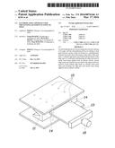
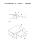
[0021] FIG. 3 is a perspective view illustrating the edge mask according to an embodiment of the present invention; and
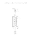
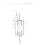
[0022] FIG. 4 is a schematic cross-sectional view illustrating an electroplating apparatus for preventing edge portions from being over-plated according to an embodiment of the present invention.
MODE FOR INVENTION
[0023] The terminology used herein is for the purpose of describing particular embodiments only and is not intended to be limiting. As used herein, the singular forms "a," "an" and "the" are intended to include the plural forms as well, unless the context clearly indicates otherwise. It will be further understood that the terms "comprise", "include", "have", etc. when used in this specification, specify the presence of stated features, integers, steps, operations, elements, components, and/or groups of them but do not preclude the presence or addition of one or more other features, integers, steps, operations, elements, components, and/or groups thereof.
[0024] Unless otherwise defined, all terms including technical and scientific terms used herein have the same meaning as commonly understood by those skilled in the art to which this invention belongs. It will be further understood that terms, such as those defined in commonly used dictionaries, should be interpreted as having a meaning that is consistent with their meaning in the context of the relevant art and the present disclosure, and will not be interpreted in an idealized or overly formal sense unless expressly so defined herein.
[0025] Reference will now be made in greater detail to an electroplating apparatus for preventing edge portions from being over-plated according to an exemplary embodiment of the present invention in conjunction with the accompanying drawings.
[0026] In the related art, the edge portions of a steel plate are prevented from being over-plated by reducing the density of an electric current applied to the edge portions by placing cathode edge masks adjacent to the edge portions. In contrast, according to the present invention, anode edge masks are added to the cathode edge masks in order to reduce the density of the electric current applied to the edge portions of the steel plate, thereby innovatively improving the ability to prevent the edge portions from being over-plated.
[0027] In addition, it is possible to adjust the current density of the edge portions, since the area of the anodes covered by the anode edge masks, i.e. the area by which the electrical connection between the edge portions of the steel plate and the anodes is blocked, can be increased or decreased.
[0028] FIG. 2 is a side view illustrating an edge mask according to an embodiment of the present invention, and FIG. 3 is a perspective view illustrating the edge mask according to an embodiment of the present invention. Referring to FIGS. 2 and 3, the cathode edge mask 11 according to an embodiment of the present invention is disposed to be adjacent to the edge portion of the steel plate in order to prevent the edge portion of the steel plate from being electrically connected to the anode. The cathode edge mask 11 has an inner recess in the direction toward the steel plate such that the edge portion can pass through the recess when the steel plate is subjected to continuous plating, whereby the anode is prevented from being electrically connected to the edge portion of the steel plate.
[0029] It is preferable that the recess has an inclined cross-section that spreads in the direction toward the steel plate. This configuration can reliably reduce the current density at the edge portion of the steel plate when the distance between the steel plate and the cathode edge mask 11 varies in response to the steel plate slipping to the right or left in the width direction during continuous plating.
[0030] In addition, a support 13 is connected to the other surface of the cathode edge mask 11. One end of the support 13 is connected to a mask driving unit 16 that moves the cathode edge mask 11 forward and backward. When the steel plate slips during continuous plating, the mask driving unit 16 can move the cathode edge mask 11 toward or away from the steel plate, thereby adjusting the position of the cathode edge mask 11 with respect to the steel plate. The mask driving unit 16 may be a device able to execute forward and reverse motions, for example, a cylinder device. The mask driving unit 16 may be actuated using a servomotor for the purpose of precise control.
[0031] The support 13 is coupled with connecting portions 14 that extend in the top-bottom direction such that the connecting portions 14 can be coupled with an anode edge mask. The connecting portions 14 may extend through the support 13, and may be in the shape of two rods positioned at both sides.
[0032] The connecting portions 14 can be fitted into positioning holes 15 formed in the anode edge mask 12, thereby being coupled with the anode edge mask 12. A pair of the anode edge masks 12 may be coupled with the connecting portions 14 such that the anode edge masks 12 are disposed parallel to each other on both sides of the cathode edge mask 11. Since the two or more positioning holes 15 may be formed in the direction toward the steel plate, the area by which the anode is covered can be adjusted in response to the positions of the positioning holes 15 coupled with the connecting portions 14, thereby adjusting the current density at the steel plate.
[0033] The cathode edge mask 11 and the anode edge masks 12 may be formed of an insulating material. Alternatively, the anode edge masks 12 may be formed of a conductive material in order to prevent the problem that the portions of the steel plate covered by the anode edge masks 12 are non-plated. In this case, the anode edge masks 12 may have an insulating layer on the surfaces facing anodes 2 and 3 in order to prevent the anode edge masks 12 from being electrically connected to the anodes 2 and 3. This configuration can prevent the problem that the surface portions of the steel plate covered by the anode edge masks 12 are non-plated.
[0034] FIG. 4 is a schematic cross-sectional view illustrating an electroplating apparatus for preventing edge portions from being over-plated according to an embodiment of the present invention.
[0035] The steel plate 1 is positively charged to act as a cathode, and electroplating proceeds while the steel plate 1 passes between the two anodes 2 and 3. At this time, the edge portions on both sides of the steel plate 1 may be over-plated in response to current density being concentrated thereon. First, the cathode edge masks 11 are disposed adjacent to the steel plate in order to reduce the current density. Even in the case where the distance between the cathode edge masks 11 and the edge portions of the steel plate is increased, the anodes are covered by the anode masks 12 disposed between the cathode edge masks 11 and the anodes 2 and 3, whereby the current density at the edge portions can be reduced.
[0036] In addition, the anode edge mask 12 extends more than the cathode edge masks 11 in the direction toward the steel plate 1. This configuration prevents the current density from significantly increasing at the edge portions even in the case where the distance between the edge portions of the steel plate 1 and the cathode edge masks 11 is rather increased in response to the steel plate slipping in the width direction while passing between the cathode edge masks.
[0037] It is also possible to adjust the area by which electrical connection is blocked by the anode edge masks 12 by changing the positions of the positioning holes 15 of the anode edge masks 12 with which the connecting portions 14 are coupled depending on the thickness and the type of the steel plate.
[0038] When the slipping of the steel plate 1 increases, it is possible to adjust the entire positions of the cathode edge masks 11 and the anode edge masks 12 in response to variations in the width of the steel plate 1 by operating the driving units 16 connected to the supports 13.
[0039] Although the specific exemplary embodiments of the present invention have been described with reference to the accompanying drawings, it will be apparent to a person skilled in the art to which the invention relates that various changes in forms may be made without departing from the spirit or essential features of the present invention.
[0040] Therefore, the foregoing specific embodiments are intended to be illustrative in all aspects rather than limiting. The scope of the present invention shall be defined by the appended claims rather than the foregoing description. It should be interpreted that the present invention shall extend to all modifications or changes derived from the definition, ranges, and equivalents of the claims.
User Contributions:
Comment about this patent or add new information about this topic:
Images included with this patent application:
 |  |
 |  |
| Similar patent applications: | |
| Date | Title |
|---|---|
| 2015-11-05 | Apparatus for metallic particles separation |
| 2015-11-05 | Apparatus and corresponding method for purifying a fluid |
| 2015-10-22 | Apparatus for residual pesticide detection |
| 2016-02-25 | Method and apparatus analyzing a target material |
| 2016-03-17 | Apparatus for preparing hydrogen water |
| New patent applications in this class: | |
| Date | Title |
|---|---|
| 2016-07-07 | Substrate holder, a method for holding a substrate with a substrate holder, and a plating apparatus |
| 2016-07-07 | Non-uniform doping of photoelectrochemical cell electrodes |
| 2016-06-09 | Composite hardware for an electrochemical cell |
| 2016-06-09 | Synthesis of nanostructured photoactive films with controlled morphology by a flame aerosol reactor |
| 2016-06-02 | Electrochemical treatment based surface modification device |
| Top Inventors for class "Chemistry: electrical and wave energy" | |
| Rank | Inventor's name |
|---|---|
| 1 | Vamsee K. Pamula |
| 2 | Michael G. Pollack |
| 3 | Adam Heller |
| 4 | Vijay Srinivasan |
| 5 | Li-Shiang Liang |