Patent application title: CHASSIS FRAME FOR A RAIL VEHICLE
Inventors:
Christian Karner (Ilz, AT)
IPC8 Class: AB61F524FI
USPC Class:
105172
Class name: Railway rolling stock trucks locomotive frames
Publication date: 2016-03-10
Patent application number: 20160068171
Abstract:
A chassis frame for a rail vehicle having at least two bearing blocks for
bearing a torsion bar of a roll stabilizer, where openings are provided
in the longitudinal beams of the chassis frame that can receive a torsion
bar to prevent an enlargement of the overall height by a torsion bar
mounted on the roll stabilizer if the torsion bar is mounted in the
bearing blocks.Claims:
1-8. (canceled)
9. A chassis frame for a rail vehicle, comprising: at least two bearing blocks for bearing a torsion bar of a roll stabilizer; and longitudinal beams having openings for receiving a torsion bar if the torsion bar is mounted in the bearing blocks.
10. The chassis frame as claimed in claim 9, further comprising: a pipe inserted through the openings in the longitudinal beams of the chassis frame into the chassis frame and connected in an airtight and watertight manner to the chassis frame to form a closed cavity with respect to an interior of the chassis frame to receive the torsion bar mounted in the bearing blocks.
11. The chassis frame as claimed in claim 10, wherein the pipe is arranged within a transverse beam of the chassis frame which is formed as a hollow profile.
12. The chassis frame as claimed in claim 10, wherein the pipe completely penetrates two longitudinal beams and, on an outermost boundary wall of each of said two longitudinal beams, when viewed in an axial direction of the pipe, is connected in the airtight and watertight manner to the outermost boundary wall.
13. The chassis frame as claimed in claim 11, wherein the pipe completely penetrates two longitudinal beams and, on an outermost boundary wall of each of said two longitudinal beams, when viewed in an axial direction of the pipe, is connected in the airtight and watertight manner to the outermost boundary wall.
14. The chassis frame as claimed in claim 12, wherein the pipe is welded in the airtight and watertight manner to the outermost boundary wall.
15. The chassis frame as claimed in claim 13, wherein the pipe is welded in the airtight and watertight manner to the outermost boundary wall.
16. The chassis frame as claimed in claim 9, wherein the longitudinal beams are formed as a hollow profile with at least one web which is perpendicular to a longitudinal axis of the pipe and one upper and lower belt parallel to a longitudinal axis of the pipe.
17. The chassis frame as claimed in claim 9, further comprising: a bearing bracket arranged on the longitudinal beam for each of said at least two bearing blocks, said bearing bracket receiving a bearing block in a form-fitting manner.
18. The chassis frame as claimed in claim 17, wherein the bearing bracket is welded to an upper and lower belt of a longitudinal beam.
19. The chassis frame as claimed in claim 9, further comprising: a torsion bar mounted in the bearing blocks, said torsion bar being surrounded by the pipe if necessary.
Description:
CROSS-REFERENCE TO RELATED APPLICATIONS
[0001] This is a U.S. national stage of application No. PCT/EP2014/058076 filed 22 Apr. 2014. Priority is claimed on Austrian Application No. A50298/2013 filed 2 May 2013, the content of which is incorporated herein by reference in its entirety.
BACKGROUND OF THE INVENTION
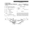
[0002] 1. Field of the Invention
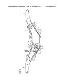
[0003] The invention relates to a chassis frame for a rail vehicle having at least two bearing blocks for bearing a torsion bar of a roll stabilizer.
[0004] 2. Description of the Related Art
[0005] In rail vehicles, but also in other vehicles, the railcar body is generally mounted in a spring-loaded manner with respect to the wheel units, such as wheel pairs or wheel sets, by way of one or a number of spring levels. The centrifugal acceleration occurring when passing through curves, at right angles to the travel and thus at right angles to the longitudinal vehicle axis, determines the tendency of the railcar body, on account of the comparatively high center of gravity of the railcar body, to bend towards the outside of the curve compared with the wheel units, consequently therefore executing a roll movement about a roll axis which is parallel to the longitudinal vehicle axis. Such roll movements above certain limit values are disadvantageous on the one hand for travel comfort. On the other hand, they bring with them the risk of damaging the permissible structure gauge and, with respect to derailment safety, impermissible one-sided wheel offloading.
[0006] In order to prevent this, roll supporting devices in the form of roll stabilizers are generally used. Their object is to counter the roll movement of the railcar body with a resistance in order to reduce the same, while the lifting and hunting movements of the railcar body relative to the wheel units, in other words the chassis, are not to be impeded. Such roll stabilizers are known in various hydraulic or purely mechanically acting embodiments. A torsion bar (torsion shaft) extending at right angles to the vehicle longitudinal direction is frequently used, as for instance is known from EP 1 075 407 B1, DE 24 21 874 A1 or EP 1 974 151 B1.
[0007] Levers attached in a torsion-proof manner on both sides of the vehicle longitudinal axis rest on these torsion bars, where the levers extend in the vehicle longitudinal direction. These levers are in turn connected to rods or such devices, which are arranged kinematically in parallel to the spring facilities of the vehicle. When compressing the suspension of the spring facilities of the vehicle, the levers resting on the torsion bar are made to rotate by way of the rods connected thereto. If, when passing through a curve, a roll movement occurs with different spring travel of the spring facilities on the two sides of the vehicle, then this roll movement results in different angles of rotation of the levers resting on the torsion bar. A torsion torque is accordingly applied to the torsion bar and, depending on the torsion rigidity thereof, balances out a counter torque resulting from its elastic deformation in the case of a specific torsion angle and thus prevents a further roll movement. Here, in the case of rail vehicles equipped with bogies, the roll supporting facilities can be provided both for the secondary spring level, i.e., between a chassis frame and the railcar body. Similarly, the roll supporting facility can also be used in the primary level, i.e., act between the wheel units and a chassis frame or, in the case of a missing secondary spring, a railcar body.
[0008] The roll stabilizer is provided both for mono-wheel running gears and also for single-axle running gears, i.e., having just one individual wheel set, and also for bogies. The part of a rail vehicle with which the vehicle moves on the rails and is guided is referred to as a running gear or chassis. A running gear with two or more wheel sets arranged in a frame is referred to as a bogie. The primary suspension and if necessary a secondary suspension form inter alia the assemblies of a bogie. The suspension between the bogie frame and the wheel sets is referred to as a primary suspension. The secondary suspension serves in bogies with dual-level suspension as a second suspension level for absorbing the shock of the vehicle body relative to the bogie frame.
[0009] If the torsion bar is mounted on the chassis frame, then it is generally arranged above or below the chassis frame. If air suspension is used as a secondary suspension, then its dimensions and its movement would require an arrangement of the torsion spring below the chassis frame. This is however not possible in many instances due to the overall height of the longitudinal beam of the chassis frame or the possibility of disassembly of the drive of the rail vehicle downwards.
SUMMARY OF THE INVENTION
[0010] It is therefore an object of the present invention to provide a chassis frame, in which, despite a torsion bar of a roll stabilizer mounted thereupon, the overall height is not increased.
[0011] This and other objects and advantages are achieved in accordance with the invention by a chassis framein which end openings (in the sense of cutouts) are provided in the longitudinal beams of the chassis frame, and can receive a torsion bar if it is mounted in bearing blocks. As a result of the torsion bar then being passed through the chassis frame and thus being integrated herein, the torsion bar is disposed within the overall height of the chassis frame.
[0012] The chassis frame is in most instances formed by longitudinal and transverse beams that are connected to one another.
[0013] The roll stabilizer is connected to two different vehicle parts of the rail vehicle, the one vehicle part generally being the running gear or chassis in the form of a chassis frame, for instance a bogie or the bogie frame, the other vehicle part being the railcar body. A rail vehicle generally has at least two running gears or chassis.
[0014] In the case at hand, the roll stabilizer formed as a torsion bar comprises, aside from, in the assembled state, the torsion bar (torsion shaft) arranged at right angles with respect to the vehicle longitudinal direction on the chassis frame, levers attached in a torque-proof manner hereto on both sides of the vehicle longitudinal axis, each lever having a tension-push rod, where each lever is connected in a hinged manner to one end of the torsion push rod and this is connected in a hinged manner with its other end to the railcar body.
[0015] The bearing blocks serve to absorb axial and transverse forces from the torsion bar, so that the axis of the torsion bar remains in its target position and can only execute a rotation about its axis.
[0016] In one particular embodiment, a pipe is provided, which is inserted into the chassis frame through the openings in the longitudinal beams of the chassis frame and is connected in an airtight and watertight manner to the chassis frame and forms a cavity that is closed with respect to the interior of the chassis frame to receive a torsion bar mounted in the bearing blocks.
[0017] As a result of the pipe for the torsion bar being passed through the chassis frame and therefore integrated herein, the pipe is disposed within the overall height of the chassis frame and does not increase the chassis frame height.
[0018] The airtight and watertight connection of the pipe to the chassis frame, approximately via seal welding, prevents the ingress of oxygen and moisture into the interior of the chassis frame, so that corrosion of the chassis frame from the inside is prevented.
[0019] In order, in any case, to guarantee the accessibility of the chassis frame from below, such as for disassembly of a drive attached the chassis, provision can be made for the pipe to be arranged within a transverse beam of the vehicle frame formed as a hollow profile. In this case, the pipe is therefore not arranged adjacent to a transverse beam, which would, similarly to a further "transverse beam", block the free cross-section of the vehicle frame and would potentially prevent access from below to a drive arranged on the vehicle frame, but instead in the transverse beam and thus completely within the outer dimensions of the transverse beam.
[0020] A hollow profile within the meaning of the invention is generally a steel pipe with a circular, square, oval or other cross-section, the wall of which is made of steel.
[0021] In order, on the one hand, to ensure a good bearing of the pipe in the vehicle frame and, on the other hand, to guarantee a good sealing of the vehicle frame, provision can be made for the pipe to completely penetrate the two longitudinal beams and, on the outermost boundary wall of the longitudinal beam in each case, viewed in the axial direction of the pipe, for it to be connected, in particular welded, in an airtight and watertight manner to the outermost boundary wall.
[0022] The longitudinal beams can likewise be formed as a hollow profile with one or a number of webs perpendicular to the longitudinal axis of the pipe and an upper and lower belt parallel to the longitudinal axis of the pipe. Multiple webs determine a good bearing of the pipe.
[0023] A bearing bracket can be provided on the longitudinal beam for each bearing block, where the bearing bracket receives the bearing block in a form-fitting manner. In addition to this form-fitting reception, the bearing block is mostly still screwed to the bearing bracket. Forces are already absorbed by the form-fit. As a result, the screw connection can be dimensioned smaller than without a form-fit, e.g., fewer screws or shorter or thinner screws.
[0024] The bearing bracket is generally fixedly connected to the longitudinal beam. In the case of longitudinal beams with an upper and lower belt, the bearing bracket can be welded to the upper and lower belt of the longitudinal beam. This produces a particularly favorable transmission of force from the torsion bar into the longitudinal beam. Here, the upper and lower belts project over the lateral boundary walls of the longitudinal beam.
[0025] If the torsion bar is mounted in the chassis frame, then the torsion bar is mounted in the bearing blocks and if necessary surrounded by the pipe.
[0026] The arrangement in accordance with the disclosed embodiments of the invention is not restricted to one roll stabilizer per chassis frame. As such, depending on the design of the chassis frame, provision can be made in these further devices for receiving torsion bars--both for torsion bars integrated in accordance with the invention in the chassis frame and also for non-inventively arranged torsion bars.
[0027] Other objects and features of the present invention will become apparent from the following detailed description considered in conjunction with the accompanying drawings. It is to be understood, however, that the drawings are designed solely for purposes of illustration and not as a definition of the limits of the invention, for which reference should be made to the appended claims. It should be further understood that the drawings are not necessarily drawn to scale and that, unless otherwise indicated, they are merely intended to conceptually illustrate the structures and procedures described herein.
BRIEF DESCRIPTION OF THE DRAWINGS
[0028] For further explanation of the invention, reference is made in the subsequent part of the description to the figures, from which further advantageous embodiments, details and developments of the invention are to be inferred, in which:
[0029] FIG. 1 shows a side view of a chassis frame in accordance with the invention;
[0030] FIG. 2 shows a plan view of the chassis frame of FIG. 1; and
[0031] FIG. 3 shows a cross-sectional view through the chassis frame of FIG. 1 along the torsion bar.
DETAILED DESCRIPTION OF THE EXEMPLARY EMBODIMENTS
[0032] FIG. 1 shows a side view of an inventive chassis frame in accordance with the invention, which is composed of two longitudinal beams 8 and two transverse beams 1 (see FIG. 2). The longitudinal beam 8 has an upper belt 6 and a lower belt 7 where the ends of the upper and lower belt 6, 7 project outwards on the exterior beyond the side walls of the longitudinal beam 8. A bearing bracket 5 is welded to the parts projecting beyond the side walls both on the upper and also lower belt 6, 7. The bearing bracket 5 has in this example two stacks of in each case a number of plates arranged vertically and in parallel, where the bearing block 4 is inserted in a form-fitting manner between the stacks. The bearing block 4 is secured against falling out of the bearing bracket 5 by a screw connection 9.
[0033] FIG. 2 shows a plan view of the chassis frame of FIG. 1, where on account of the symmetry only half of the chassis frame is shown. The symmetry axis is the vehicle longitudinal axis x. The chassis frame is also essentially symmetrical in the transverse direction y.
[0034] Aside from the longitudinal beam 8, the two transverse beams 1 are also visible, where the transverse beam 1 shown here to the left is cut open, so that the torsion bar 3 disposed therein and the pipe 2 surrounding the torsion bar 3 can be seen. The pipe 2 ends just outside of the outermost boundary wall of the transverse beam 8 and is welded there in the overhanging region to the boundary wall of the longitudinal beam 8, so that no air or moisture can penetrate between the pipe 2 and the boundary wall into the inside of the longitudinal beam 8. The pipe 2 thus forms a cavity that is sealed off from the interior of the chassis frame in order to receive the torsion bar 3. The transverse beam 1 is likewise welded to the longitudinal beam 8 in a tight manner, namely to the innermost boundary wall of the longitudinal beam 8.
[0035] The torsion bar 3 is longer than the pipe 2 and is mounted with its end in the bearing block 4, which for its part is supported by the bearing bracket 5. The torsion rod 8 is free between the boundary wall of the longitudinal beam 8 and the bearing block 4, where the rotationally-fixed lever 11 of the roll stabilizer engages here, to which in turn are fastened the hinges 12 that connect the levers to the tension push rods (not shown here).
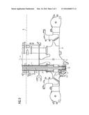
[0036] FIG. 3 shows a cross-section through the chassis frame accordingly along the torsion rod 3, namely with a view in the direction of the vehicle longitudinal axis x in FIG. 2. Here, it is apparent that the two longitudinal beams 8 are essentially box-shaped and closed and each consists of three parallel webs, which are connected to one another by the upper or lower belt 6, 7 respectively. The pipe 2 is passed through all webs and welded to the outermost web so that the pipe 2 and the outermost web are sealed with one another. The pipe 2 is pushed into the corresponding circular openings of the individual webs in a form-fitting manner and is also as a result fixed in its position. Thus, while there have been shown, described and pointed out fundamental novel features of the invention as applied to a preferred embodiment thereof, it will be understood that various omissions and substitutions and changes in the form and details of the devices illustrated, and in their operation, may be made by those skilled in the art without departing from the spirit of the invention. For example, it is expressly intended that all combinations of those elements which perform substantially the same function in substantially the same way to achieve the same results are within the scope of the invention. Moreover, it should be recognized that structures and/or elements shown and/or described in connection with any disclosed form or embodiment of the invention may be incorporated in any other disclosed or described or suggested form or embodiment as a general matter of design choice. It is the intention, therefore, to be limited only as indicated by the scope of the claims appended hereto.
User Contributions:
Comment about this patent or add new information about this topic:
| People who visited this patent also read: | |
| Patent application number | Title |
|---|---|
| 20180175230 | HYBRID INTEGRATION OF PHOTODETECTOR ARRAY WITH DIGITAL FRONT END |
| 20180175229 | INTERDIGITATED BACK CONTACT METAL-INSULATOR-SEMICONDUCTOR SOLAR CELL WITH PRINTED OXIDE TUNNEL JUNCTIONS |
| 20180175228 | Method for Manufacturing a Photovoltaic Module and Photovoltaic Module Thus Obtained |
| 20180175227 | EXPANDABLE PHOTOVOLTAIC SUBMODULES |
| 20180175226 | METHODS OF HERMETICALLY SEALING PHOTOVOLTAIC MODULES |
Images included with this patent application:
 |  |
 |  |
| Similar patent applications: | |
| Date | Title |
|---|---|
| 2016-01-07 | Chassis for rail vehicles |
| 2016-04-21 | Carrying structure of a rail vehicle |
| 2016-01-07 | Solebar for a railway vehicle |
| 2016-02-11 | Suspended recreational vehicle drive |
| 2016-03-03 | Method and apparatus for controlling electrical currents in a vehicle |
| New patent applications in this class: | |
| Date | Title |
|---|---|
| 2016-06-09 | Bogie frame for a railway vehicle, associated bogie and method for manufacturing such a bogie frame |
| 2015-04-23 | Running gear unit for a rail vehicle |
| Top Inventors for class "Railway rolling stock" | |
| Rank | Inventor's name |
|---|---|
| 1 | James W. Forbes |
| 2 | Ajith Kuttannair Kumar |
| 3 | Tomasz Bis |
| 4 | Shunichi Nakao |
| 5 | Takehiro Nishimura |