Patent application title: PLANT PROCESSING SYSTEM AND METHOD
Inventors:
Peter Ryan Hall (Vancouver, CA)
Assignees:
Paolo Developments Ltd.
IPC8 Class: AB26D136FI
USPC Class:
241191
Class name: Solid material comminution or disintegration apparatus rotary striking member, rotor structure
Publication date: 2016-01-28
Patent application number: 20160023365
Abstract:
A plant processor, comprising a cylindrical rotatable drum for receiving
plant matter and having a plurality of slots, a rotatable cutting reel
positioned below the rotatable drum and being rotatable in an opposite
direction to the drum, the cutting reel comprising a cylindrical rod and
a plurality of longitudinal cutting blades operable to cut plant material
extending through the slots in the drum, a horizontal support having a
top surface and a plurality of magnets recessed in the support to be
flush with the top surface, and a cutting knife having ends and a cutting
edge, the knife mounted on the top surface of the support and held in
place by the magnets, wherein the support maintains the cutting edge of
the knife in an operable position near the reel and the drum for cutting
plant material that extends through the plurality of slots in the drum;
and a motor to rotate the reel and the drum.Claims:
1. A plant processor, comprising: a) a cylindrical rotatable drum for
receiving plant matter, the rotatable drum having a plurality of slots;
b) a rotatable cutting reel positioned below the rotatable drum and being
rotatable in an opposite direction to the drum, the cutting reel
comprising a cylindrical rod and a plurality of longitudinal cutting
blades connected thereto operable to cut plant material extending through
the slots in the drum; c) a horizontal support having a top surface and a
plurality of magnets recessed in the support to be flush with the top
surface; and (d) a cutting knife having ends and a cutting edge, the
knife being mounted on the top surface of the support and held in place
by the magnets, wherein the support maintains the cutting edge of the
knife in an operable position near the reel and the drum for cutting
plant material that extends through the plurality of slots in the drum;
and e) a motor to rotate the reel and the drum.
2. The plant processor of claim 1 further comprising a frame adjacent each end of the knife and a pair of slots defined in the frame to receive said ends of the knife, wherein the knife is slidable along the slots towards and away from the reel.
3. The plant processor of claim 2 further comprising an adjustment mechanism cooperating with the knife to urge the knife towards the reel.
4. The plant processor of claim 3 wherein the adjustment mechanism is adjustable by a user to slide the knife within the slots.
Description:
FIELD OF THE INVENTION
[0001] This invention relates to systems for removing extraneous material from plants, and more particularly to systems for removing such material from herbs, berries and medicinal crops.
BACKGROUND OF THE INVENTION
[0002] Current plant processing machines are inefficient, costly to clean and repair, and prone to breakdown. An improved plant processing system is desired.
SUMMARY OF THE INVENTION
[0003] In one aspect the present invention provides a plant processor, including: a) a rotatable drum for receiving plant matter, the rotatable drum having a plurality of slots; b) a rotatable cutting reel positioned below the rotatable drum, the cutting reel rotatable in the opposite direction of the drum; c) a cutting knife horizontally positioned below the top of the reel; the cutting knife maintained in position by one or more magnets, the cutting knife slidable along a slot in a frame of the processor by a rod extending above the knife; and d) a motor to rotate a shaft secured to the reel, the shaft having a groove to frictionally engage a ring, the ring supporting the drum, whereby rotation of the reel rotates the drum in the opposite direction.
[0004] In another aspect, the present invention provides a plant processor, comprising: a cylindrical rotatable drum for receiving plant matter, the rotatable drum having a plurality of slots; a rotatable cutting reel positioned below the rotatable drum and being rotatable in an opposite direction to the drum, the cutting reel comprising a cylindrical rod and a plurality of longitudinal cutting blades connected thereto operable to cut plant material extending through the slots in the drum; a horizontal support having a top surface and a plurality of magnets recessed in the support to be flush with the top surface; and a cutting knife having ends and a cutting edge, the knife being mounted on the top surface of the support and held in place by the magnets, wherein the support maintains the cutting edge of the knife in an operable position near the reel and the drum for cutting plant material that extends through the plurality of slots in the drum; and a motor to rotate the reel and the drum.
[0005] In some embodiments, the plant processor further comprising a frame adjacent each end of the knife and a pair of slots defined in the frame to receive said ends of the knife, wherein the knife is slidable along the slots towards and away from the reel.
[0006] In some embodiments, the plant processor further comprising an adjustment mechanism cooperating with the knife to urge the knife towards the reel. In some embodiments, the adjustment mechanism is adjustable by a user to slide the knife within the slots.
GENERAL DESCRIPTION OF THE DRAWINGS
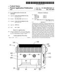
[0007] FIG. 1 is a front view of a plant processing apparatus according to the invention;
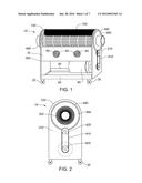
[0008] FIG. 2 is a side view thereof;
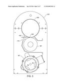
[0009] FIG. 3 is a cross sectional side view thereof;
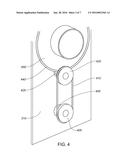
[0010] FIG. 4 is a perspective side view of the system showing the drive system therein;
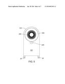
[0011] FIG. 5 is an alternate side view thereof;
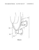
[0012] FIG. 6 is a view of the drive groove therein;
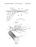
[0013] FIG. 7 is a side view showing the cutting blade and cutting reel;
[0014] FIG. 8 is a perspective view of the cutting blade;
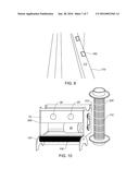
[0015] FIG. 9 is a view of the bed bar; and
[0016] FIG. 10 is a disassembled front view of the apparatus.
DETAILED DESCRIPTION OF THE INVENTION
[0017] As seen in FIG. 1, plant processing apparatus 10 includes two pairs of wheels 20, 30. Wheels 30 may be slightly larger, or have a greater distance to base members 40, 50 to provide apparatus 10 a slight "tilt" to one side relative to the surface the machine 10 is placed on. Instead of wheels 20, 30, legs or other means to support apparatus 10 may be used.
[0018] Wheel pairs 20, 30 are secured to front and rear base members 40, 50. Base members 40, 50 support motor 60, which is conventionally powered, for example by means of a plug or battery. Front plate 70 is positioned above motor 60 and has two apertures 90, 95. Apertures 90, 95 are sized and shaped to receive a hose for a dust collector (not shown). When in contact with a dust collector a small vacuum is created in apparatus 10. Behind front plate 70 is a rotatable cutting reel 80. Cutting reel 80 has characteristics similar to that of a reel used in a hand operated lawn mower, and generally includes a horizontal cylindrical rod attachable to reel pulley 420 and a plurality of blades arranged around the rod, the blade supported by supports.
[0019] Drum 200 is positioned above reel 80 and at the top of drum 200 is brush 100 supported by upper frame 120. Drum 200 has a plurality of slots 110. Slots 110 are sized to either allow or prevent the wanted materials to pass through drum 200 through to cutting reel 80. Brush 100 is in contact with slots 110 when slots 110 are at the upper portion of their rotation, and prevents material from getting stuck in slots 110 or being flung by centrifugal force.
[0020] As seen in FIG. 3, between cutting reel 80 and drum 200 is a flat cutting blade 160. Cutting blade 160 is horizontally positioned such that the cutting edge 165 is just below the top of reel 80 as shown in FIG. 8. Reel 80 and drum 200 rotate in opposite directions.
[0021] Cutting blade 160 is held in place by bed bar 170 and slots 230 in side panels 300, 310 as well as screws (not shown) for additional support. Bed bar 170 has magnets 180 (such as rare earth magnets) on its top surface 172, as see in FIG. 9, that maintain blade 160 in position. Knife adjustment rod 190 can be used to adjust the horizontal position of blade 160 as it becomes worn and to move blade 160 laterally to compensate for different levels of wear along cutting edge 165. This arrangement allows blade 160 to be removed easily, sharpened and replaced.
[0022] As seen in FIGS. 4, 5, and 6, drive shaft 400 extends from motor 60, and rotates drive pulley 405 at the end of drive shaft 400. Drive belt 410 causes reel pulley 420 and reel shaft 425 to rotate, thereby rotating reel 80. Reel shaft 425 has groove 430 positioned between reel pulley 420 and side panel 310. Groove 430 is sized to receive o-ring 440 positioned on the circumference of ring 450. Ring 450 is sized to receive and hold drum 200. Therefore, by rotating reel shaft 425, ring 450 is caused to rotate, and drum 200 rotates thereby in the opposite direction of the rotation of reel 80.
[0023] As seen in FIGS. 5 and 6, on the opposite side 300, reel shaft 425 has groove 430 as described above.
[0024] When using apparatus 10, plant material, such as herbs, berries, medicinal marijuana, including leafs, stems and/or debris are fed into the rotating drum 200 from a first, elevated side 120. The plant material is drawn to the lower portion of drum 200, through a slot 110 (if such material can fit through slot 110) and is cut by blade edge 165 and reel 80.
[0025] Plant material falling into reel 80 is drawn through aperture 90 or 95 and into a dust collector, where it can be retrieved later.
[0026] The above-described embodiments have been provided as examples, for clarity in understanding the invention. A person of skill in the art will recognize that alterations, modifications and variations may be effected to the embodiments described above while remaining within the scope of the invention as defined by the claims appended hereto.
User Contributions:
Comment about this patent or add new information about this topic:
Images included with this patent application:
 |  |
 |  |
 |  |
 |  |
| Similar patent applications: | |
| Date | Title |
|---|---|
| 2016-02-11 | Food processing apparatus and method |
| 2016-02-11 | Food processing apparatus and method |
| 2016-03-31 | Fluid processing method |
| 2016-05-05 | Device and method for processing of feed material |
| 2016-03-10 | Planetary mill and method of milling |
| New patent applications in this class: | |
| Date | Title |
|---|---|
| 2019-05-16 | Beater wheel for pulverizer mill and method of assembly |
| 2016-06-23 | Hammer mill disc refurbishment process and apparatus |
| 2016-02-18 | Vertical shaft impactor |
| 2015-12-03 | Blade for shaving ice |
| 2015-05-21 | Portable frozen confection machine |
| New patent applications from these inventors: | |
| Date | Title |
|---|---|
| 2021-11-04 | Apparatus, method and system for wet or dry processing of plant material |
| 2014-03-27 | Plant processing system and method |
| Top Inventors for class "Solid material comminution or disintegration" | |
| Rank | Inventor's name |
|---|---|
| 1 | Tai Hoon K. Matlin |
| 2 | Charles Sued |
| 3 | Aron Abramson |
| 4 | Knut Kjaerran |
| 5 | Hartmut Pallmann |