Patent application title: STACKABLE STAY-COLD STEIN OR DRINKING GLASS
Inventors:
Herbert Martin (Paducah, KY, US)
IPC8 Class: AA47G1923FI
USPC Class:
2064595
Class name: Special receptacle or package with indicia or area modified for indicia
Publication date: 2016-01-28
Patent application number: 20160022069
Abstract:
A drinking vessel that has the capability to be stackable and which, by
using regular water ice or dry ice, has the ability to maintain a cold
temperature for the beverages while not diluting the potency of the
liquid or diminishing the quality of the taste. The stackable aspect of
the design allows the containers to be nestled within each other allowing
for greater quantities of the vessels to be shipped at a single time. A
sealable, removable bottom allows for the ice to be secured with the
hollow chilling chamber. A handle, which may be formed into the vessel at
the time of casting or may be attached after shipping, along with the
base that is larger in diameter than the top because to the stacking
feature, create the appearance of a traditional beer stein.Claims:
1. A stackable stein, comprising: a body, said body comprising: an outer
cylindrical wall wider at a first base end than at an opposite first
upper end; an inner cylindrical wall having a second base end and an
opposite second upper end; wherein: the second base end comprises a
closed base region, the first upper end and the second upper end form a
common upper region, and the first base end and the second base end
extend to substantially a same orthogonal distance from the common upper
region; a frustoconical annular region formed between an outer surface of
the inner cylindrical wall and an inner surface of the outer cylindrical
wall; and a detachable bottom configured to releasably attach to the
first base end.
2. The stackable stein of claim 1, comprising: a detachable handle configured to releasably attach to at least an outer surface of the outer cylindrical wall.
3. The stackable stein of claim 1, wherein at any particular orthogonal distance from a top of the common upper region towards the first base end: an outer diameter of the outer cylindrical wall is less than or substantially equal to an outer diameter of the frustoconical annular region at approximately that same particular orthogonal distance from a bottom of the common upper region.
4. The stackable stein of claim 3, wherein the outer diameter of the outer cylindrical wall at that particular orthogonal distance is approximately equal to the outer diameter of the frustoconical annular region at approximately that same particular orthogonal distance.
5. The stackable stein of claim 2, wherein the outer cylindrical wall comprises an indentation on an outer surface of the outer cylindrical wall; and wherein the detachable handle comprises a protruding region complementary in shape to the indentation, wherein the protruding region engages the indentation to releasably attach the detachable handle to the outer surface of the outer cylindrical wall.
6. The stackable stein of claim 2, wherein the outer cylindrical wall comprises a plurality of holes between an outer surface and the inner surface of the outer cylindrical wall; and wherein the detachable handle comprises a respective complimentary protruding region complementary in shape to one of the plurality of holes, wherein each protruding region engages one of the plurality of holes to releasably attach the detachable handle to the outer surface of the outer cylindrical wall.
7. The stackable stein of claim 1, wherein the detachable bottom screws into the first base end.
8. The stackable stein of claim 1, wherein the detachable bottom snaps into the first based end.
9. The stackable stein of claim 1, wherein the detachable bottom comprises a central opening configured to fit around the closed base region.
10. The stackable stein of claim 1, wherein a seal between the detachable bottom and the first base end is water-tight.
11. The stackable stein of claim 1, wherein: the inner cylindrical wall and the closed base region form a container for holding liquid; the annular region is shaped to accept a mass of frozen coolant, wherein the mass of frozen coolant is kept separate from any contents of the container for holding liquid.
12. The stackable stein of claim 11, wherein the detachable bottom forms a reservoir for collecting portion of the frozen coolant that melt.
13. The stackable stein of claim 1, wherein an outer surface of the outer cylindrical wall includes a region for affixing a logo to the stackable stein.
14. The stackable stein of claim 1, wherein a first diameter of the second base end of the inner cylindrical wall is substantially equal to a second diameter of the second upper end.
15. The stackable stein of claim 1, wherein a first diameter of the second base end of the inner cylindrical wall is less than a second diameter of the second upper end.
16. The stackable stein of claim 2, wherein the detachable handle is attached using at least an adhesive.
17. The stackable stein of claim 1, comprising: a grip-enhancing surface around at least a portion of an outer surface of the outer cylindrical wall.
18. A plurality of stackable steins, comprising: a plurality steins, each stein comprising: a body, said body comprising: an outer cylindrical wall wider at a first base end than at an opposite first upper end; an inner cylindrical wall having a second base end and an opposite second upper end; wherein the first upper end and the second upper end form a common upper region and the first base end and the second base end extend to substantially a same orthogonal distance from the common upper region; a frustoconical annular region formed between an outer surface of the inner cylindrical wall and an inner surface of the outer cylindrical wall; wherein the plurality of steins are nested together in an arrangement from a bottom stein to a top stein whereby the common upper region of a lower stein in the arrangement is fitted within the frustoconical annular region of an adjacent, next-higher stein in the arrangement.
19. A kit of disposable steins comprising: a plurality stackable steins, each stein comprising: a body, said body comprising: an outer cylindrical wall wider at a first base end than at an opposite first upper end; an inner cylindrical wall having a second base end and an opposite second upper end; wherein the first upper end and the second upper end form a common upper region and the first base end and the second base end extend to substantially a same orthogonal distance from the common upper region; a frustoconical annular region formed between an outer surface of the inner cylindrical wall and an inner surface of the outer cylindrical wall; wherein the plurality of steins are nested together in an arrangement from a bottom stein to a top stein whereby the common upper region of a lower stein in the arrangement is fitted within the frustoconical annular region of an adjacent, next-higher stein in the arrangement. a plurality of detachable bottoms, each bottom configured to releasably attach to the first base end of one of the plurality of stackable steins; and a plurality of detachable handles; each handle configured to releasably attach to at least an outer surface of the outer cylindrical wall of one of the plurality of stackable steins.
20. The kit of claim 19, comprising: a freezing tray with a structure for holding liquid coolant to be frozen, wherein the structure is complementary in shape to the frustoconical annular region whereby coolant frozen in the structure fits within the frustoconical annular region.
Description:
BACKGROUND
[0001] 1. Field
[0002] The present invention relates to cold-liquid drinking vessels and more particularly to beer steins.
[0003] 2. Related Art
[0004] In U.S. Pat. No. 4,424,990, White et al disclose thermo-chromic compositions which change color with temperature changes. These compositions are commercially available and are used in thermometers and novelty items, and simply reflect the ambient temperature of the liquids within the vessels. They do nothing to affect the temperatures or to keep the beverage cold.
[0005] In U.S. Pat. No. 5,156,283, Sampson teaches that a beer stein should be of suitable material so as to not be conductive of heat and proposes a wooden stein. Further, Sampson teaches that decorative emblems can be embedded in the wood to increase the attractiveness of the drinking container, however this proposal has a limiting effect as to what materials may be used in the construction of the beer stein.
[0006] Fremin, in U.S. Pat. No. 4,919,983 teaches that by using plastic thermo-chromic materials in forming a baby bottle, it is possible to indicate when the contents of the bottle are too hot to drink, but again, this does nothing to alter the temperature of the bottle contents.
SUMMARY
[0007] Embodiments of the present invention relate to a stackable stein that includes a body. The body includes an outer cylindrical wall wider at a first base end than at an opposite first upper end; an inner cylindrical wall having a second base end and an opposite second upper end; and a frustoconical annular region formed between an outer surface of the inner cylindrical wall and an inner surface of the outer cylindrical wall. The inner and outer cylindrical walls are configured such that a) the second base end comprises a closed base region, b) the first upper end and the second upper end form a common upper region, and the first base end and the second base end extend to substantially a same orthogonal distance from the common upper region. The stackable stein also includes a detachable bottom configured to releasably attach to the first base end. The stackable stein may also include a detachable handle configured to releasably attach to at least an outer surface of the outer cylindrical wall.
[0008] Another embodiment of the present invention relates to a plurality of stackable steins. Each of the steins include a body formed from a) an outer cylindrical wall wider at a first base end than at an opposite first upper end; b) an inner cylindrical wall having a second base end and an opposite second upper end; wherein the first upper end and the second upper end form a common upper region and the first base end and the second base end extend to substantially a same orthogonal distance from the common upper region; and c) a frustoconical annular region formed between an outer surface of the inner cylindrical wall and an inner surface of the outer cylindrical wall. Moreover, the plurality steins are nested together in an arrangement from a bottom stein to a top stein whereby the common upper region of a lower stein in the arrangement is fitted within the frustoconical annular region of an adjacent, next-higher stein in the arrangement.
[0009] Yet another embodiment of the present invention relates to a kit of disposable steins that includes a plurality of stackable steins; a plurality of detachable bottoms, each bottom configured to releasably attach to the first base end of one of the plurality of stackable steins; and a plurality of detachable handles; each handle configured to releasably attach to at least an outer surface of the outer cylindrical wall of one of the plurality of stackable steins. Each of the steins include a body formed from a) an outer cylindrical wall wider at a first base end than at an opposite first upper end; b) an inner cylindrical wall having a second base end and an opposite second upper end; wherein the first upper end and the second upper end form a common upper region and the first base end and the second base end extend to substantially a same orthogonal distance from the common upper region; and c) a frustoconical annular region formed between an outer surface of the inner cylindrical wall and an inner surface of the outer cylindrical wall. Moreover, the plurality steins are nested together in an arrangement from a bottom stein to a top stein whereby the common upper region of a lower stein in the arrangement is fitted within the frustoconical annular region of an adjacent, next-higher stein in the arrangement. The kit may also include a freezing tray with a structure for holding liquid coolant to be frozen, wherein the structure is complementary in shape to the frustoconical annular region whereby coolant frozen in the structure fits within the frustoconical annular region.
[0010] It is understood that other embodiments of the present invention will become readily apparent to those skilled in the art from the following detailed description, wherein it is shown and described only various embodiments of the invention by way of illustration. As will be realized, the invention is capable of other and different embodiments and its several details are capable of modification in various other respects, all without departing from the spirit and scope of the present invention. Accordingly, the drawings and detailed description are to be regarded as illustrative in nature and not as restrictive.
BRIEF DESCRIPTION OF THE DRAWINGS
[0011] Various aspects of a system and method for anesthesia monitoring are illustrated by way of example, and not by way of limitation, in the accompanying drawings, wherein:
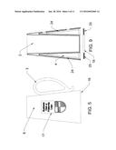
[0012] FIG. 1 is a sectional view of the beer stein showing the ear handle inserted in place and with no bottom provided.
[0013] FIG. 2 is an exploded sectional view of the beer stein including a snap-in bottom and the adhesive attachment for the exploded ear handle showing the receptive holes for the attaching the ear handle.
[0014] FIG. 3 is a top view pictorial of the items described in FIG. 2.
[0015] FIG. 4 is a bottom view pictorial of the items described in FIG. 1.
[0016] FIG. 5 is an exterior view of the items in FIG. 1 along with any arbitrary insignia.
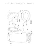
[0017] FIG. 6 is an exploded pictorial of the beer stein with the snap-in bottom attachable ear handle and the attachment adhesive.
[0018] FIG. 7 is a pictorial of an alternate design for the ear handle.
[0019] FIG. 8 is a pictorial the screw-in or snap-in bottom showing a grip handle.
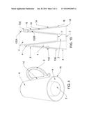
[0020] FIG. 9 is sectional view of the beer stein with the snap-in bottom showing the reflective-foil covered Styrofoam liner.
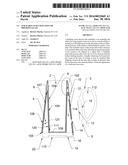
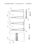
[0021] FIG. 10 is a sectional view of the drinking vessel without the ear handle and showing the stacking capability of the invention.
[0022] FIG. 11 is an exterior view of the drinking vessel without a handle showing a roughened gripping surface.
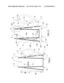
[0023] FIG. 12 is a sectional view of the drinking vessel with the screw-on bottom in place.
[0024] FIG. 13 is a sectional view of the drinking vessel with the screw-on bottom exploded.
[0025] FIG. 14 is an enlarged sectional view of the drinking vessel with the screw-on bottom in place.
[0026] FIG. 15 is an enlarged sectional view of the drinking vessel.
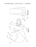
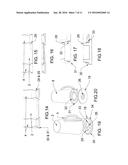
[0027] FIG. 16 is an enlarged sectional view of the screw-on bottom.
[0028] FIG. 17 is an enlarged sectional detail of the drinking vessel.
[0029] FIG. 18 is an enlarged sectional detail of the screw-on bottom.
[0030] FIG. 19 is a top view pictorial of the stein and the screw-on bottom.
[0031] FIG. 20 is a bottom view pictorial of the beer stein and the screw-on bottom.
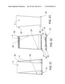
[0032] FIG. 21 is a sectional view showing the glass, the funnel, and the screw-on bottom assembled.
[0033] FIG. 22 is a sectional view showing the funnel and the screw-on bottom disassembled.
[0034] FIG. 23 is a sectional view of the glass.
[0035] FIG. 24 is a pictorial view of the assembled stein viewed from above right.
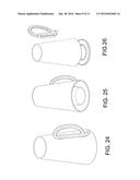
[0036] FIG. 25 is a pictorial view of the assembled stein viewed from below left.
[0037] FIG. 26 is an exploded pictorial viewed from above left.
[0038] FIG. 27 is a sectional view showing a shallow bottom interior section with a full deep-bottom lid and cinch top.
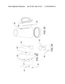
[0039] FIG. 28 is a diagram showing how the stein shape is derived from a truncated cone.
[0040] FIG. 29 is a pictorial view showing how one truncated cone nestles into another.
[0041] FIG. 30 is a pictorial showing how the attachable handle does not penetrate the outer cone.
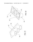
[0042] FIG. 31 is a pictorial view showing the bottom of the ice tray.
[0043] FIG. 32 is a pictorial view showing the top view of the ice tray.
DETAILED DESCRIPTION OF THE PREFERRED EMBODIMENTS
[0044] The detailed description set forth below in connection with the appended drawings is intended as a description of various embodiments of the invention and is not intended to represent the only embodiments in which the invention may be practiced. The detailed description includes specific details for the purpose of providing a thorough understanding of the invention. However, it will be apparent to those skilled in the art that the invention may be practiced without these specific details. In some instances, well known structures and components are shown in block diagram form in order to avoid obscuring the concepts of the invention.
[0045] The beer stein, with the base larger than the top lip, symbolically represents the art of brewing and drinking beer. Until now, there has been no way of economically providing the natural image of the festival at a beer festival as most of the beer at such events is served out of plain plastic or paper cups. By utilizing this present invention, fraternities at beer blasts can provide a drinking mug with the fraternity insignia on the side with the possibility of also providing a souvenir of the occasion. The additional bonus comes from being able to keep the beer chilled without diluting it with the water from melting ice. The present invention need not be restricted to beer containers as it is equally effective at keeping other beverages cold without the container having the requisite handle of the beer stein. For example, colas and other soft drinks can be kept cold without the unwanted effect of having them diluted by melting ice. Another benefit arising from the design of the present invention is, by using the detached handle, the ability of wholesalers to stack the drinking containers for ease of shipping great quantities.
[0046] In the prior art, many inventors have experimented with the materials used in creating the beer mug and with decorative designs affixed to or imbedded in the containers, however no one has created a design that is stackable, larger at the bottom than at the top, and is able to maintain the coldness of the liquid. Most of these inventions demonstrate no utilitarian purposes beyond those exhibited by the original, conventional designs of time-honored beer steins as most are add-on advertising gimmicks.
[0047] Currently, there does exist a double-wall, plastic freezer mug that contains a gelatinous liquid that is permanently sealed within the walls. This freezer mug is to be placed in the freezer for an extended time to achieve a frozen state for the contained liquid. The significant differences between this item and the present invention is that (1) it is not stackable, (2) it is not designed to ever be disposable, and (3) its design is not applicable to low-cost materials making it impractical for use at public ventures such as beer festivals.
[0048] Beer steins and other vessels for consuming liquids have traditionally been made of a variety of materials including but not limited to glass, ceramic, plastic, Styrofoam, and metal. Ideally, a drinking container is one that should be not conductive of heat, will not affect the taste or consistency of the beverage, and will not drip condensation from the air which has accumulated on the outside of the container onto furniture or other surfaces. All of the above materials, with the exception of Styrofoam will, in most surrounding climates that are warmer than the liquid contents of the container, collect condensate on the exterior walls of the container which will then run down onto the surface upon which the container is sitting. A vessel that is designed to collect the condensate within a hollow chamber and which has that said hollow chamber insulated from the warmer outer temperatures both on the sides and on the bottom by a Styrofoam lining will effectively combat that problem.
[0049] With most liquids such as soda, tea, milk, or lemonade, it is desirable that they be consumed at a cold temperature, and this is accomplished by drinking rapidly or by floating ice in the liquid within the container. When ice made from solid water is floated in the said liquid, it will melt in the liquid, turning the ice back into water and thereby reducing the potency of the liquid that is being consumed and making it less concentrated than when originally poured. If ice is not placed in the liquid for cooling purposes, the temperature of said liquid immediately begins to become heated by the ambient external temperature making it unpleasant to drink within a short period of time. By keeping the coolant, which effectively might be regular ice or dry ice, separate from the contained liquid, a desirable cold temperature can be maintained while at the same time retaining the original potency of the liquid.
[0050] Because beer steins have traditionally been made of various materials--metal, glass, and ceramic being chief among the materials being used, and with modern-day disposable cups being made of paper, wax-covered paper, plastic, and Styrofoam, the stackable stay-cold beer stein is designed in such a manner as to permit interchangeable parts of varying materials. For instance, the outer cone shell may be made of plastic lined with Styrofoam and then with reflective foil while the inner cup section can be made of plastic or ceramic or glass depending upon which material is most pleasing to the lips of the user. Reusable steins can have a screw-on, insulated bottom while disposable cups may have a snap on, plastic bottom for securing the dry or water ice coolant within the hollow, cooling chamber.
[0051] Because the stackable, stay-cold beer stein will be desirable for use at festive, memorable occasions, logos of fraternities, businesses, of festivals may be either printed on the outsides of the mugs, or they may be affixed to the outsides by peel-off labels such as those used on the year ID tags of automobile license renewals or from sheets printed in a manner similar to postage stamps. Likewise, the detached handles may be attached to the mugs after shipment by using peel-off tape that is already affixed to the ears prior to shipping.
[0052] The present invention, a stackable, stay-cold drinking vessel, is shown in FIG. 24, FIG. 25, and FIG. 26. The detailed description set forth below in connection with the drawings is intended as a description of various embodiments of the invention and is not intended to represent the only embodiment in which the invention may be practiced. The detailed description includes specific details for the purpose of providing a thorough understanding of the invention, however it will be readily apparent to those skilled in the art that there may be overlapping specifics and that the invention may be practiced without these specific details.
[0053] Embodiments of the present invention relate to a drinking vessel that, with the introduction of water ice or dry-ice into a specially designed chilling compartment has the ability to maintain a cold temperature to the liquid in the consumption part of the vessel without diluting is potency. This design feature that is built into the vessel also has the ability to allow the vessels to be stacked thereby allowing for greater ease in shipping. The vessel may be made of a variety of materials--i.e. paper, wax coated paper, plastic, Styrofoam, ceramic, metal, glass, or any combination thereof. The invention can be made to be disposable, or it can be made to be kept for re-use or to save as a souvenir item.
[0054] The basic concept for the shape of the stay-cold beer stein could be said to be derived from a slender cone that has been truncated into three equal heights (FIG. 28. and FIG. 29). The circumference of the top 41 of the base section 42 is congruent with the circumference of the base 41 of the middle section 40. When the middle section 40 of the cone is inverted FIG. 30, inserted into the base section, and sealed at the top, it forms the basic design for the stay-cold beer stein. There is no purpose for the top section of the cone in this design.
[0055] Also, in its most basic form, this present invention would be made of a disposable material such as thin plastic, paper, or wax covered paper, and it would consist of four separate pieces--the stackable structure 1, the attachable handle 3, the adhesive tape 13 for attaching the handle to the stackable structure, and the snap-in bottom 19 for securing the ice within the chilling chamber 4, shown in FIG. 1, FIG. 2, FIG. 25 and FIG. 26. If the inner vertical annular supports 21 and the outer vertical annular supports 20 on the snap-in bottom 19 are tall enough and fit under a drip cap (see FIG. 2 and FIG. 8) the water from melting ice will not seep out onto the table upon which the stein might be resting. Rather, it will be collected in the closing ring 23 (of FIG. 8) or 37 & 38 (of FIG. 27) of the snap-in bottom.
[0056] One reason for having an attachable handle for the beer stein is to maintain the stackable aspect of the design for ease of shipping as shown in FIG. 10. For his reason, upper openings 10 and lower openings 14 may be designed into the basic structure allowing for the handles 3 to be attached after shipment. To achieve this end, adhesive tape 13 with a pull off tab similar to double sticky tape is attached to the support surface 15 on the handle. When the upper support nodule 11 and the lower support nodule 5 are inserted into the said upper and lower openings, the said tape presses against a section on the outer funnel 12 and this causes the handle to become permanently affixed to the funnel of the stackable beer stein. See FIG. 1, FIG. 2, and FIG. 3. An alternate design for the upper support nodule FIG. 7 extends farther 22 into the chilling chamber and provides a hook shape on the top 18 for the purpose of locking the upper support into the chilling chamber and giving additional support without the danger of the handle being pulled out by the force of lifting. A third handle concept would be for the slot 44 FIG. 30 in the outer shell to be simply an indention in the exterior and not penetrate completely through thereby leaving the chilling chamber water tight. The support nodule 45 would still be affixed inside the slot with double sticky sealing tape 46. If the design concept is to be used as a simple glass with a chilling chamber for drinking such beverages as colas, soda pops, tea, or milk, there would be no requirement for the support nodule holes as a handle would not be required. However, since the shape would taper upward, a gripping surface 28, FIG. 11, might be designed into the shape to aid in lifting the glass. Aside from the novelty of drinking out of a vessel where the bottom has the appearance of a greater diameter than the top rim, with either design, the shape would still be more stable when resting on a table because there would be more weight at the bottom than at the top due to the nature of the design. The design lends itself to having the lower rim of the funnel shape 16, as shown in FIG. 2 & FIG. 4, rather than the bottom lid resting on the table for the sake of stability. For the ease of inserting and removing the bottom lid from the main structure, a hand grip 26, as shown in FIG. 8 & FIG. 19, is designed into the lid, and the bottom, interior of the one-piece casting 7 should be sufficiently shallow enough for this to happen.
[0057] In order for the chilling chamber to function most effectively, a Styrofoam funnel-shaped insulating liner with a reflective inner lining 24, as shown in FIG. 9 & FIG. 22, may be designed into the outer funnel portion of the basic structure. Also for insulating purposes, an annular Styrofoam ring 25 may be included with the snap-in or screw-in bottoms. In either the inexpensive version of all plastic or the more permanent version of the invention, if the bottom of the interior section of the one piece casting 7 does not extend to the bottom circumference ring 16 of the exterior section, then there would be no need for the donut hole in the bottom lid, and it would be cast as one piece 37. In this configuration, the thin plastic outer vertical annular supports 20 on the snap-in would extend farther into the hollow of the outer ring. It would also curve outward in a semi-circular shape before curving inward 38, to fit snugly under an annular drip cap 39 to prevent the melted water from seeping out onto the support upon which the stein is sitting, and the bottom lid would become a holding receptacle for the melted ice. Since the upper circumference is curving inward, this would provide for easier installation of the lid as well as creating a tighter, more leak-proof seal.
[0058] In its more permanent and expensive form, this present invention would be made of more durable materials such as metal, heavy plastic, ceramic, glass, Styrofoam, or combinations of the said materials, and it would be suitable for being washed. It could be made of as many as five different parts which could possibly be assembled by screwing the parts together as shown in FIGS. 19, 20, 21, 22, & 23. The purpose for being able to disassemble all the parts would be for most effective dishwasher cleaning. The outer funnel-shaped shell 8 would be lined with Styrofoam 24, as shown in FIG. 22, and would be threaded at the top rim 35.
[0059] Likewise, the inner glass would be threaded at the top rim 36, as shown in FIG. 23, in order to screw into the outer funnel-shell. The inner glass of the tankard would also be threaded at the bottom rim 32, as shown in FIG. 17 & FIG. 23, to receive the inner threaded portion 33 of the bottom lid. The outer funnel-shaped shell would also be threaded on the inside of the bottom rim 34, in order to receive the outer threaded portion of the bottom lid 35 (see FIG. 22.)
[0060] When the bottom lid is screwed in tightly into the assembled beer stein or drinking vessel, a water tight seal is formed between the abutting surfaces 28, 19, 30, 31 as shown in FIGS. 17, 18, & 19.
[0061] Functionally, the most effective way to introduce ice into the chilling chamber of the stay-cold beer stein would be to fill the chilling chamber with water to a predetermined fill-line and place it inverted into the freezer. When the stein is then removed to be used, the water-tight bottom could be affixed and the vessel would be ready to be filled with any preferred beverage. Secondly, the most practical, time-efficient, and cost effective way of introducing ice into the chilling chamber is simply to scoop crushed ice into the vessel by using the handle as a scoop and then inserting the removable water-tight bottom. Another way to introduce the ice would be to have the ice preformed into the requisite funnel shape by having plastic or polyurethane ice trays that are designed to accomplish this end as shown in FIG. 31 and FIG. 32. By this method, trays 47 are formed having an outer truncated cone 48 with a sealed bottom 49 and an inner truncated cone 43 with sealed top 51 that together form a freezing chamber 50. Ultimately, for use in commercial establishments, ice machines could be manufactured to produce the funnel-shaped ice that would be necessary to accommodate the business at a commercial establishment.
[0062] In order to make any drinking glass or beer stein event specific to the occasion or sponsor specific, the business, club, or organization logo can be printed on the exterior of the mug at the manufacturing plant, or it may be affixed later at the usage destination by using paste-on decals 17 as shown in FIG. 5.
[0063] Referring back to FIG. 1 and FIG. 2, aspects of the present invention relate to a stackable stein that includes a body. The body includes an outer cylindrical wall 106 wider at a first base end 105 than at an opposite first upper end 107 such that the outer cylindrical wall 106 slants outwardly at its bottom. The stein body also includes an inner cylindrical wall 104 having a second base end 111 and an opposite second upper end 109. The body includes a frustoconical annular region, or cavity, 114 formed between an outer surface 120 of the inner cylindrical wall 104 and an inner surface 121 of the outer cylindrical wall 106. The inner and outer cylindrical walls 104, 106 are configured such that a) the second base end 111 comprises a closed base region 108, b) the first upper end 107 and the second upper end 109 form a common upper region 102, and the first base end 105 and the second base end 111 extend to substantially a same orthogonal distance d1 (see FIG. 1) from the common upper region 102. The stackable stein also includes a detachable bottom 110 configured to releasably attach to the first base end 105. The stackable stein may also include a detachable handle 112 configured to releasably attach to at least an outer surface of the outer cylindrical wall.
[0064] As a result of this construction, the stein body is stackable or nestable because at any particular orthogonal distance d2 from a top of the common upper region 102 towards the first base end 105 an outer diameter of the outer cylindrical wall 106 is less than or substantially equal to an outer diameter of the frustoconical annular region 114 at approximately that same particular orthogonal distance d3 from a bottom of the common upper region 102. The stein of FIG. 1 can thereby be stacked together as shown in FIG. 10. The distance d3, which is "approximately d2" from the bottom of the common upper region 102, is "approximate" because the steins (as shown in FIG. 10) do not nest perfectly. There is a gap 130 between the bottom of the common upper region 102A of an upper-located stein and the top of the upper common region 102B of a lower-located stein. If this gap 130 did not exist, then the relationship about the outer diameter of the outer cylindrical wall being less than the outer diameter of the frustoconical annular region would be true for d2=d3. However, the gap 130 can be as much as a few millimeters and, thus, the relationship about those outer diameters holds true for d2≈d3 where d3 is larger than d2 an amount the same as the size of the gap 130.
[0065] Also, in most instances, the outer diameter of the outer cylindrical wall at that particular orthogonal distance is approximately equal to the outer diameter of the frustoconical annular region at approximately that same particular orthogonal distance. This relationship expresses the construction that, when nested, the gap 132 (see FIG. 10) between two adjacent stein's outer cylindrical walls is negligible in size and can be a millimeter or less.
[0066] When a plurality of steins are stacked together, the plurality of steins are nested together in an arrangement from a bottom stein 134 to a top stein 136 whereby the common upper region 102B of a lower stein 134 in the arrangement is fitted within the frustoconical annular region of an adjacent, next-higher stein 136 in the arrangement. The positional terms such as "bottom", "upper", "lower", etc. as used herein are used for convenience with respect to a particular frame of reference illustrated in the figures. However, one of ordinary skill will recognize that there terms can be changed without departing from the scope of the present invention. For example, the nested arrangement of FIG. 10 can also occur if the frame of reference were flipped 180 degrees so that a "lower" item" would then become a "higher" item.
[0067] The previous description is provided to enable any person skilled in the art to practice the various embodiments described herein. Various modifications to these embodiments will be readily apparent to those skilled in the art, and the generic principles defined herein may be applied to other embodiments. Thus, the claims are not intended to be limited to the embodiments shown herein, but are to be accorded the full scope consistent with each claim's language, wherein reference to an element in the singular is not intended to mean "one and only one" unless specifically so stated, but rather "one or more." All structural and functional equivalents to the elements of the various embodiments described throughout this disclosure that are known or later come to be known to those of ordinary skill in the art are expressly incorporated herein by reference and are intended to be encompassed by the claims. Moreover, nothing disclosed herein is intended to be dedicated to the public regardless of whether such disclosure is explicitly recited in the claims. No claim element is to be construed under the provisions of 35 U.S.C. §112, sixth paragraph, unless the element is expressly recited using the phrase "means for" or, in the case of a method claim, the element is recited using the phrase "step for."
[0068] Below is a legend table for the elements depicted in FIGS. 1-32. Functional names and labels have been given to each element but are not intended to limit these elements to only these functions but rather to aid the reader in understanding embodiments of the present invention.
[0069] 1. Stackable structure of the beer stein
[0070] 2. Chamber for holding the liquid
[0071] 3. Stein handle or ear
[0072] 4. Chilling chamber for holding the dry ice or water ice
[0073] 5. Lower support nodule on ear to aid attachment to stackable structure
[0074] 6. Thickened material for one-piece casting of the stackable structure
[0075] 7. Bottom of interior section of one-piece casting
[0076] 8. Outer funnel portion of beer stein
[0077] 9. Inner wall of beer stein
[0078] 10. Upper opening to receive top support nodule on detached handle
[0079] 11. Upper support nodule on handle to support and aid attachment to stackable structure
[0080] 12. Portion on outer funnel portion that receives the attachment tape
[0081] 13. Attachment tape
[0082] 14. Lower opening to receive bottom support nodule on detached handle
[0083] 15. Surface on detached handle that receives the attachment tape
[0084] 16. Bottom circumference rim of the one-piece casting
[0085] 17. Paste-on insignia
[0086] 18. Alternate design for upper support nodule on handle
[0087] 19. Snap-in or screw-in bottom
[0088] 20. Outer vertical annular supports on snap-in bottom
[0089] 21. Inner vertical annular supports on snap-in bottom
[0090] 22. Alternate design of upper support nodule (item 11)
[0091] 23. Closing ring for snap-in bottom
[0092] 24. Styrofoam insulating cone on "the inner surface of the outer funnel (item 8)
[0093] 25. Annular Styrofoam insulation on closing ring of the snap-in bottom
[0094] 26. Hand grip on snap-in or screw-in bottom
[0095] 27. Rounded upper drinking rim
[0096] 28. Annular compression seal on tankard
[0097] 29. Inner annular compression seal on screw-in bottom
[0098] 30. Outer annular compression seal on screw-in bottom
[0099] 31. Annular compression seal on funnel
[0100] 32. Inner threads on tankard connecting to screw-in bottom
[0101] 33. Inner threads on screw-in bottom that connect to tankard
[0102] 34. Outer threads on screw-in bottom that connect to matching threads on funnel
[0103] 35. Top threads on funnel shell
[0104] 36. Top threads on glass or tankard
[0105] 37. One-piece bottom lid
[0106] 38. Leak preventing cinch top of bottom lid
[0107] 39. Leak preventing cinch within the outer cone
[0108] 40. Second lowest truncated cone
[0109] 41. Shared diameter on lowest and second lowest truncated cones
[0110] 42. Lowest truncated cone
[0111] 43. Inverted second lowest cone
[0112] 44. Slot that does not penetrate the outer cone
[0113] 45. Support on handle
[0114] 46. Adhesive to fit in slot
[0115] 47. Ice tray
[0116] 48. Outer cone of ice tray
[0117] 49. Bottom of truncated outer cone on ice tray
[0118] 50. Hollow portion of ice tray to receive water for freezing
[0119] 51. Top of truncated inner cone on ice tray
User Contributions:
Comment about this patent or add new information about this topic:
Images included with this patent application:
 |  |
 |  |
 |  |
 |  |
 |  |
 |  |
| Similar patent applications: | |
| Date | Title |
|---|---|
| 2016-03-10 | Adjustable support for a glove such as a baseball, softball, or cricket glove |
| 2016-02-04 | First aid kit with speech, music, or instructional sound emission |
| 2015-10-29 | Stackable liquor glass set |
| 2016-01-21 | Can type container changeable to type of cup or glass |
| 2016-01-28 | Stay-cold drinking can |
| New patent applications in this class: | |
| Date | Title |
|---|---|
| 2019-05-16 | Configurable food trays and modular containers |
| 2017-08-17 | Label including rfid tag, product box to which label including rfid tag is attached, and method for attaching rfid tag and label |
| 2017-08-17 | Reusable labels for infant's bottles or children's cups |
| 2016-12-29 | Theft-inhibiting shopping basket |
| 2016-09-01 | Label for decorating a bottle, bottle and method of manufacture of such a label |
| New patent applications from these inventors: | |
| Date | Title |
|---|---|
| 2014-06-26 | Pest extermination blanket |
| 2010-12-23 | Saucer-shaped gyroscopically stabilized vertical take-off and landing aircraft |
| 2010-11-11 | Saucer shaped gyroscopically stabilized vertical take-off and landing aircraft |
| Top Inventors for class "Special receptacle or package" | |
| Rank | Inventor's name |
|---|---|
| 1 | Donald E. Weder |
| 2 | Brett R. Glass |
| 3 | Daniel Lee Bizzell |
| 4 | Andrea Biondi |
| 5 | Nicole E. Glass |