Patent application title: Using an Arc-Produced Gas in the Production of Energy from Biomass
Inventors:
IPC8 Class: AF23G5027FI
USPC Class:
110346
Class name: Furnaces process incinerating refuse
Publication date: 2016-01-21
Patent application number: 20160018107
Abstract:
A system for generating energy from biomass uses an arc-produced gas,
either in the primary burn process to achieve higher burning
temperatures, in a secondary after-burn process to reduce pollutants, or
in both the primary burn process and after-burn process. The use of
arc-produced gas results in increased efficiency, reduced emissions, and
additional heat energy. Heat produced is used, for example, to generate
electricity. In some embodiments, the arc-produced gas is combined with
another fuel such as oil or natural gas for desired burn characteristics
and/or for economic reasons.Claims:
1. A system for generating energy from biomass, the system comprising: a
device for producing a gas, the device comprising a pressure vessel
having there within a volume of feedstock and a pair of electrodes with
electric power provided to the electrodes, producing an arc between the
electrodes, the arc submerged within the feedstock such that interaction
between the arc and the feedstock produces the gas; a primary combustion
chamber into which an amount of biomass is placed and combusted using the
gas, thereby producing heat; and an exhaust interfaced to the primary
combustion chamber for removing flue gases.
2. The system for generating energy from biomass of claim 1, wherein the primary combustion chamber is agitated.
3. The system for generating energy from biomass of claim 1, wherein air is injected into the primary combustion chamber.
4. The system for generating energy from biomass of claim 1, wherein the heat from the primary combustion chamber is used to generate power.
5. The system for generating energy from biomass of claim 1, further comprising a secondary combustion chamber interfaced to the exhaust, wherein an amount of the gas is combined with the flue gases from the primary combustion chamber and combusted, producing additional heat.
6. The system for generating energy from biomass of claim 5, wherein the heat generated in the primary combustion chamber and the additional heat generated in the secondary combustion chamber are used to generate power.
7. The system for generating energy from biomass of claim 6, wherein the power is electricity.
8. A method for generating energy from biomass, the method comprising: producing a gas within a pressure vessel by exposing a volume of feedstock to an arc between electrodes, the electric arc submerged in the volume of feedstock; combusting an amount of biomass and an amount of the gas in a primary combustion chamber, thereby producing heat; and exhausting flue gases from the primary combustion chamber.
9. The method for generating energy from biomass of claim 8, further comprising agitating the primary combustion chamber.
10. The method for generating energy from biomass of claim 8, further comprising injecting air into the primary combustion chamber.
11. The method for generating energy from biomass of claim 8, further comprising generating power from the heat.
12. The method for generating energy from biomass of claim 8, further comprising mixing the flue gases from the primary combustion chamber with an additional amount of the gas and combusting the flue gases and the additional amount of the gas in a secondary combustion chamber, thereby producing additional heat.
13. The method for generating energy from biomass of claim 12, further comprising generating power from the heat and the additional heat.
14. The method for generating energy from biomass of claim 12, wherein the step of mixing the flue gases from the primary combustion chamber with an additional amount of the gas is performed prior to the flue gases and the additional amount of the gas enters the secondary combustion chamber.
15. The method for generating energy from biomass of claim 14, wherein before the step of mixing the flue gases from the primary combustion chamber with an additional amount of the gas is performed, a step of cooling the additional amount of the gas is performed.
16. The method for generating energy from biomass of claim 12, wherein the step of mixing the flue gases from the primary combustion chamber with an additional amount of the gas is performed within the secondary combustion chamber.
17. A method for generating energy from biomass, the method comprising: producing a gas within a pressure vessel by exposing a volume of feedstock to an arc between electrodes, the electric arc submerged in the volume of feedstock; combusting an amount of biomass and an amount of the gas in a primary combustion chamber, thereby producing heat; exhausting flue gases from the primary combustion chamber; mixing the flue gases from the primary combustion chamber with an additional amount of the gas; and combusting the flue gases and the additional amount of the gas in a secondary combustion chamber, thereby producing additional heat.
18. The method for generating energy from biomass of claim 8, further comprising injecting air into the primary combustion chamber.
19. The method for generating energy from biomass of claim 17, wherein the step of mixing the flue gases from the primary combustion chamber with an additional amount of the gas is performed prior to the flue gases and the additional amount of the gas enters the secondary combustion chamber.
20. The method for generating energy from biomass of claim 19, wherein before the step of mixing the flue gases from the primary combustion chamber with an additional amount of the gas is performed, a step of cooling the additional amount of the gas is performed.
Description:
CROSS-REFERENCE TO RELATED APPLICATION
[0001] This application claims the benefit of U.S. provisional application No. 62/026,102 filed on Jul. 18, 2014, the disclosure of which is incorporated by reference.
FIELD
[0002] This invention relates to the field of Energy Production and more particularly to a system, method and apparatus for using an arc-produced gas, here within referred to as Magnegas, in the process of producing energy from biomass.
BACKGROUND
[0003] It is known to use many different forms of biomass to produce energy. The most common way to produce energy from biomass is to burn the biomass, as has been done for centuries by burning wood or other biomass materials to produce heat, cook, produce light, etc. Another way to produce energy from biomass is to capture gases (e.g. methane gas) from landfills and sewerage treatment plants for later burning of the captured gases. In recent years, methods of converting biomass into liquid fuels in a process called "gasification" has produced combustible gases, which reduces various kinds of emissions from the latter biomass combustion, especially particulate emissions.
[0004] Using biomass to produce energy has many advantages compared to using fossil fuels. First, biomass is typically renewable over a short period of time. Biomass captured from wood production, urban waste, etc. is continually available. Biomass from crop residuals such as the straw remaining after heat is removed and corn stover (leaves and stalks) is available every year after harvest. Several crops are grown for the purpose of generating biomass, hopefully not displacing food production, such as grasses, sugar cane, trees, etc. For example, short-rotation trees allow trimming of branches every three to eight years and survive for many years, providing several crops of biomass.
[0005] Many reports have been produced showing advantages of producing energy from biomass, including numerous environmental advantages over burning fossil fuels. For example, there is little probability that biomass from a crop of corn will pollute a large body of water like the Gulf of Mexico.
[0006] Direct burning of biomass, for example to produce steam to turn a turbine, has been shown to be less efficient, in that much of the heat is wasted and some levels of air pollution are produced during the burning. To improve upon the efficiency, co-firing with, for example, coal is sometimes performed, reducing operating costs and certain emissions typically resulting from coal burning (e.g., sulfur and mercury).
[0007] Biomass gasification is performed by heating the biomass with a controlled amount of oxygen and under pressure, which creates a mixture of hydrogen and carbon monoxide, often called syngas. Syngas is, for example, burned to produce steam that is directed at a turbine connected to a generator that produces electricity, etc. Biomass gasification is generally cleaner and more efficient that direct combustion of biomass. It is also possible to convert syngas into a liquid biofuels, useful for example in mobile applications such as vehicles.
[0008] Burning or gasifying biomass emits carbon into the atmosphere. In order to further improve the processing and use of biomass, cleaner burning systems are needed, otherwise, the cost and inefficiencies of scrubbing systems reduce the benefits of producing energy from biomass.
[0009] What is needed is an incineration system that uses an arc-produced gas (e.g. Magnegas) to facilitate proper combustion and/or secondary combustion of biomass to limit pollutants that are emitted into the atmosphere.
SUMMARY
[0010] A system for generating energy from biomass uses an arc-produced gas either in the primary burn process to achieve higher flue temperatures, in a secondary after-burn process to reduce pollutants, or in both the primary burn process and secondary (after-burn) process. In some embodiments, the arc-produced gas is combined with another fuel such as oil or natural gas to produce the desired burn characteristics required for the particular biomass and/or for economic reasons.
[0011] In one embodiment, a system for generating energy from biomass is disclosed including a device for producing a gas. The device for producing the gas comprising a pressure vessel having there within a volume of feedstock and a pair of electrodes, electric power is provided to the electrodes, producing an arc between the electrodes, the arc being submerged within the feedstock and the interaction between the arc and the feedstock produces the gas. The system includes a primary combustion chamber into which an amount of biomass is placed and combusted using the gas, thereby producing heat. An exhaust interfaced to the primary combustion chamber provides for removing flue gases.
[0012] In another embodiment, a method for generating energy from biomass is disclosed including producing a gas within a pressure vessel by exposing a volume of feedstock to an arc between the electrodes that are submerged within the feedstock and combusting an amount of biomass and an amount of the gas in a primary combustion chamber, thereby producing heat. Flue gases are then exhausted from the primary combustion chamber.
[0013] In another embodiment, a method for generating energy from biomass is disclosed including producing a gas within a pressure vessel by exposing a volume of feedstock to an arc between the electrodes then combusting an amount of biomass and an amount of the gas in a primary combustion chamber, thereby producing heat. Flue gases from the primary combustion chamber are mixed with an additional amount of the gas and the flue gases and the additional amount of the gas are combusted in a secondary combustion chamber, thereby producing additional heat.
BRIEF DESCRIPTION OF THE DRAWINGS
[0014] The invention can be best understood by those having ordinary skill in the art by reference to the following detailed description when considered in conjunction with the accompanying drawings in which:
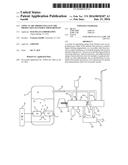
[0015] FIG. 1 illustrates a schematic view of an exemplary system for generating energy from biomass.
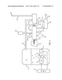
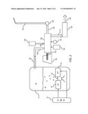
[0016] FIG. 2 illustrates a schematic view of a second exemplary system for generating energy from biomass.
DETAILED DESCRIPTION
[0017] Reference will now be made in detail to the presently preferred embodiments of the invention, examples of which are illustrated in the accompanying drawings. Throughout the following detailed description, the same reference numerals refer to the same elements in all figures.
[0018] Throughout this description, the apparatus is described as a system for producing energy from biomass, including any type of biomass such as crops dedicated to energy production, crop residue, municipal waste, waste from wood/paper production, forest residue, municipal and industrial waste, etc.
[0019] Referring to FIG. 1, an exemplary system for the production of an arc-produced fluid herein called Magnegas, which is typically in gaseous form as used herein. This is but an example of one system for the production of Magnegas, as other such systems are also anticipated. Examples of fully operational systems for the production of Magnegas can be found in U.S. Pat. No. 7,780,924 issued Aug. 24, 2010, U.S. Pat. No. 6,183,604 issued Feb. 6, 2001, U.S. Pat. No. 6,540,966 issued Apr. 1, 2003, U.S. Pat. No. 6,972,118 issued Dec. 6, 2005, U.S. Pat. No. 6,673,322 issued Jan. 6, 2004, U.S. Pat. No. 6,663,752 issued Dec. 16, 2003, U.S. Pat. No. 6,926,872 issued Aug. 9, 2005, and U.S. Pat. No. 8,236,150 issued Aug. 7, 2012, all of which are incorporated by reference. The production of such a fluid (e.g. Magnegas) is performed by exposing a feedstock 22 to the plasma of an electric arc 18, which is supplied electricity from a power source 10, either AC power, DC power, or pulsed-DC power. The feedstock 22 is circulated within a pressure vessel 12 and is injected into the plasma of an electric arc 18 between two electrodes 14/16, causing the feedstock 22 to react, depending upon the composition of the feedstock 22, the composition of the electrodes 14/16 used to create the arc, the pressure within the pressure vessel 12, flow rates, etc. One exemplary feedstock 22 is oil, and more particularly, used vegetable or animal oil such as that from deep-fat fryers, etc. Of course, any oil is anticipated, including unused vegetable oil and oil from animal fat.
[0020] Any feedstock 22 is anticipated either in fluid form or fluid mixed with solids such as fine-grain metal dust as found in used motor oil, etc. The gas 24 produced from this process is typically combustible and the composition of the gas 24 is dependent upon the fluid base of the feedstock 22 and the composition of the electrodes 14/16.
[0021] In the example in which the feedstock 22 is vegetable oil and the electrodes 14/16 are carbon, the oil molecules separate within the plasma of the electric arc 18 into a gas 24 referred to here-within as Magnegas, typically including hydrogen (H2) and carbon monoxide (CO) atoms, which percolate to the surface of the feedstock 22 for collection (e.g. extracted through a feed line 26. This gas 24 (e.g. Magnegas) is similar to synthetic natural gas or syngas, but the gas produced through this process behaves differently and produces a higher temperature burn. In embodiments in which at least one of the electrodes 14/16 that form the electric arc 18 is made from carbon, the electrode(s) 14/16 and serves as a source of charged carbon particles (e.g. carbon nanoparticles) that become suspended within the gas 24 and are collected along with the gas 24, thereby changing the burning properties of the resulting gas 24.
[0022] In examples in which the feedstock 22 is a petroleum-based liquid, the exposure of feedstock 22 that is petroleum-based to the arc (as above) results in a gas 24 that includes polycyclic aromatic hydrocarbons which, in some embodiments, are quasi-nanoparticles that are not stable and, therefore, some of the polycyclic aromatic hydrocarbons will form/join to become nanoparticles or a liquid. Therefore, some polycyclic aromatic hydrocarbons as well as some carbon particles/nanoparticles are present in the resulting gas 24. In some embodiments, some of the carbon particles or nanoparticles are trapped or enclosed in poly cyclic bonds. Analysis of the gas 24 produced by the electric arc 18 typically includes polycyclic aromatic hydrocarbons that range from C6 to C14. The presence of polycyclic aromatic hydrocarbons as well as carbon particles or nanoparticles contributes to the unique burn properties of the resulting gas 24. This leads to higher burning temperatures of the gas 24.
[0023] In another example, the feedstock 22 is used motor oil and at least one of the electrodes 14/16 is carbon. In this, the petroleum molecules separate within the plasma of the electric arc 18 into a gas 24 that includes hydrogen (H2) and aromatic hydrocarbons, which percolate to the surface of the liquid feedstock 22 (petroleum) for collection. In some embodiments, the gas 24 made by this process includes suspended carbon particles since at least one of the electrodes of the electric arc 18 is made from carbon and serves as the source for the charged carbon particles or nanoparticles that travel with the manufactured hydrogen and aromatic hydrocarbon gases and are collected along with, for example, the hydrogen and aromatic hydrocarbon molecules, thereby changing the burning properties of the resulting gas 24, leading to a hotter flame. In this example, if the feedstock 22 is used motor oil and the collected gas 24 includes any or all of the following: hydrogen, ethylene, ethane, methane, acetylene, and other combustible gases to a lesser extent, plus suspended charged carbon particles or nanoparticles that travel with these gases.
[0024] The resulting gas 24 is fed into either one or both burning operations as shown in FIG. 1. The gas 24 produced by the above operation, referred to as Magnegas, is introduced to the process of burning the biomass 130 at any step of the burning process.
[0025] In the exemplary incineration system shown in FIGS. 1 and 2, biomass 130 is staged before entry into the system in, for example, a hopper or pile of biomass 130. Some amount of the biomass 130 is fed into a primary combustion chamber 140 through a feed mechanism 134, for example, through a feed screw. Within the primary combustion chamber 140, heat is generated by burning of the biomass 130 and/or burning of the gas 24. In some embodiments, air is injected to improve the burning of the biomass 130, for example by a pump or blower 144. In some embodiments, a another fuel 138 such as oil or natural gas is also injected into the primary combustion chamber 140, either with separate injectors 139 or mixed with the gas 24 before the gas 24 is injected into the primary combustion chamber 140. The gas 24 travels from the pressure vessel 12 through a feed line 26 and into the primary combustion chamber 140 through a feed line 180, either separate, or in conjunction with another fuel 138 such as oil or natural gas. The gas 24 produces a significantly higher temperature, providing a more complete burning of the biomass 130, reducing emissions and waste. In some embodiments, an agitator 142 agitates and/or rotates the primary combustion chamber 140 to expose more of the biomass 130 and effectively/thoroughly burn all of the biomass 130 within the primary combustion chamber 140.
[0026] For brevity purposes, the exit for solids from the primary combustion chamber 140 is not shown, but it is anticipated that a dumping action or another screw device will remove residual solids (not shown) from the primary combustion chamber 140.
[0027] In some embodiments, as shown in FIG. 1, exhaust gases from the kiln are directed into a secondary combustion chamber 150 through an exhaust mechanism 145. In some such embodiments, the exhaust mechanism 145 is a simple length of insulated or uninsulated pipe, transferring exhaust gases into the secondary combustion chamber 150. In some such embodiments, the exhaust mechanism 145 includes a device 143 that treats and/or scrubs the exhaust gases by, for example, cooling the exhaust gases or filtering the exhaust gases. In some such embodiments, the device 143 is a chiller that cooled cools the exhaust gases before the exhaust gases are mixed with the gas 24 (Magnegas) from a gas feed line 182. Either the exhaust gases or the exhaust gases mixed with the gas 24 then enter the secondary combustion chamber 150 where the exhaust gases and optionally the gas 24 are combusted.
[0028] In some embodiments, some of the gas 24 is also feed directly into the secondary combustion chamber 150 through a gas line 184. The secondary burn takes place in the secondary combustion chamber 150, re-combusting the exhaust gases from the primary burn chamber 140. The secondary burn further combusts, producing exhaust gases that contain fewer pollutants, for example, reducing dioxin by breaking down the molecular bonds of dioxin. By using gas 24 in the secondary burn process, the resulting exhaust which travels out of the system through an exhaust device/chimney 152 is cleaner than if the exhausts from the initial burn were allowed into the atmosphere.
[0029] In some embodiments, as shown in FIG. 2, the exhaust 145 from the primary burning chamber 140 is released into the atmosphere. In some such embodiments the exhaust 145 from the primary burning chamber 140 is scrubbed by a scrubber device 155 before being released into the atmosphere. In either such embodiment, it is anticipated that, optionally, the exhaust 145 be eventually released into higher levels of the atmosphere through a chimney 152.
[0030] The burning of the biomass, along with the gas 24 and, optionally, with other fuels (e.g., oil, gas, etc.) generates heat 141/151. This heat 141/151 is used to generate power 192 (e.g. electrical power) using an energy conversion system 190, for example, using the heat to produce steam that turns a steam turbine or providing the heat to a fuel cell.
[0031] In summary, the gas 24 as produced within the electric arc 18 is used in any or all of the following incineration steps: the gas 24 is used in the primary burning chamber 140 to improve burning of the biomass 130; the gas 24 is mixed with exhaust gases 145 from the primary incineration and, the mixed exhaust gases 145 and gas 24 is burned in a secondary combustion chamber 150; and the gas 24 is fed directly into the secondary combustion chamber 150 to completely burn all exhaust gases 145 from the primary burning process. In all cases, it is anticipated that the gas 24 (e.g. Magnegas) is either used as a sole fuel to facilitate combustion, or is used in conjunction with another fuel including, but not limited to, oil, propane, natural gas, synthetic natural gas, diesel, gasoline, etc., depending upon temperatures required and economic factors.
[0032] In some embodiments, the primary burn process in the primary burn chamber 140, after initiation, continues thorough combustion of the biomass 130 being incinerated in the primary burn chamber 140, without further injection of other fuels. In such, in some embodiments, the gas 24 is mixed with exhaust gases 145 from the primary combustion chamber 140 and, the mixed exhaust gases 145 and gas 24 is burned; and/or the gas 24 is injected into the secondary combustion chamber 150 to completely burn all exhaust fumes from the primary burning process.
[0033] Note that, although it is shown that the gas 24 is co-produced at the location of the biomass 130 to heat 192 operation, there is no limitation on the location for the production of the gas 24 and it is equally anticipated that the gas 24 be produced at a remote location and the gas 24 is piped or placed in containers that are transported to the location of the biomass 130 to heat 192 operation.
[0034] Equivalent elements can be substituted for the ones set forth above such that they perform in substantially the same manner in substantially the same way for achieving substantially the same result.
[0035] It is believed that the system and method as described and many of its attendant advantages will be understood by the foregoing description. It is also believed that it will be apparent that various changes may be made in the form, construction and arrangement of the components thereof without departing from the scope and spirit of the invention or without sacrificing all of its material advantages. The form herein before described being merely exemplary and explanatory embodiment thereof. It is the intention of the following claims to encompass and include such changes.
User Contributions:
Comment about this patent or add new information about this topic:
Images included with this patent application:
 |  |
 |
| Similar patent applications: | |
| Date | Title |
|---|---|
| 2015-11-26 | Waste energy recovery system |
| 2011-10-20 | Air-cooled grate block |
| 2011-03-10 | Catalyst ash protector |
| 2012-03-08 | Furnace protector |
| New patent applications in this class: | |
| Date | Title |
|---|---|
| 2016-06-30 | Method and facility for incinerating, melting and vitrifying organic and metal waste |
| 2016-05-19 | Three step ultra- compact plasma system for the high temperature treatment of waste onboard ships |
| 2016-04-21 | Waste treatment apparatus and method |
| 2016-02-25 | Waste gasification melting apparatus and waste gasification melting method using the same |
| 2016-01-28 | A reactor for processing feed material |
| Top Inventors for class "Furnaces" | |
| Rank | Inventor's name |
|---|---|
| 1 | Toshihiko Yamada |
| 2 | Mario Magaldi |
| 3 | Terutoshi Uchida |
| 4 | Masayuki Taniguchi |
| 5 | Douglas C. Comrie |