Patent application title: AERATING FUEL INJECTOR SYSTEM FOR A GAS TURBINE ENGINE
Inventors:
IPC8 Class: AF23R328FI
USPC Class:
239 5
Class name: Fluid sprinkling, spraying, and diffusing processes of fuel injection
Publication date: 2016-01-14
Patent application number: 20160010866
Abstract:
An aeration system for a fuel injector system of a gas turbine engine
includes a air tank in communication with a fuel injector and method of
operation thereof.Claims:
1. An aeration system for a fuel injector system of a gas turbine engine
comprising: an air tank in communication with a fuel injector.
2. The aeration system as recited in claim 1, wherein said air tank receives a pressurized air from a source.
3. The aeration system as recited in claim 2, wherein said source is a section of the gas turbine engine.
4. The aeration system as recited in claim 1, wherein said air tank is in communication with said fuel injector at a nozzle.
5. The aeration system as recited in claim 1, wherein said air tank is in communication with said fuel injector at a mixing chamber upstream of a nozzle.
6. A gas turbine engine comprising: a fuel injector system without a pilot fuel injection system.
7. The gas turbine engine as recited in claim 6, further comprising an air tank in communication with a fuel injector of said fuel injector system.
8. The gas turbine engine as recited in claim 6, further comprising an air tank in communication with each of a multiple of fuel injectors of said fuel injector system.
9. A method of aerating a fuel injector of a gas turbine engine comprising: selectively releasing air from an air tank for mixing with the fuel injector.
10. The method as recited in claim 9, further comprising: charging the air tank from a high pressure compressor.
11. The method as recited in claim 9, further comprising: charging the air tank from a source external to the gas turbine engine.
12. The method as recited in claim 9, further comprising: charging the air tank from a source external to an aircraft.
13. The method as recited in claim 9, further comprising: mixing the air from the air tank at a nozzle of the fuel injector.
14. The method as recited in claim 9, further comprising: mixing the air from the air tank at a mixing chamber upstream of a nozzle of the fuel injector
Description:
[0001] This application claims priority to U.S. Patent Appln. No.
61/766,411 filed Feb. 19, 2013.
BACKGROUND
[0002] The present disclosure relates to a gas turbine engine and, more particularly, to a fuel injector system therefor and method of operation thereof.
[0003] Gas turbine engines, such as those which power modern commercial and military aircraft, include a compressor section to pressurize a supply of air, a combustor section to burn a hydrocarbon fuel in the presence of the pressurized air, and a turbine section to extract energy from the resultant combustion gases and generate thrust.
[0004] The combustor section generally includes a multiple of of circumferentially distributed fuel injectors that axially project into a combustion chamber to supply the fuel mixed with the pressurized air. Gas turbine engines typically include multiple individually controlled centralized staging valves with multiple fuel supply manifolds that deliver fuel to the fuel injectors. There is one fuel supply manifold for each stage, thus, each fuel injector may have multiple fuel supply connections, one for each stage. These multi-manifold fuel systems may require many fuel supply tubes of multiple shapes and sizes to feed the differential staged fuel injectors.
[0005] The fuel injectors direct pressurized fuel from a manifold to one or more combustion chambers and prepare the fuel to be mixed with air for combustion. Each fuel injector typically has an inlet fitting connected to the manifold, a stem connected at one end to the fitting, and a nozzle assembly connected to the other end of the stem to spray the fuel into the combustion chamber. A fuel conduit extends through the stem to supply the fuel from the inlet fitting to the nozzle assembly. Appropriate valves and/or flow dividers can be provided to direct and control the flow of fuel through the nozzle assembly.
[0006] The nozzle assembly often includes pilot and main nozzles. Generally, the main nozzles are for normal and high power situations, while only the pilot nozzles are used for start. The pilot nozzles have relatively small orifices and may be more prone to coke formation. Coke formation may result in narrowed fuel orifices, uneven fuel burn and increased maintenance requirements as fuel injectors with pilot nozzles are typically designed to be readily removable.
SUMMARY
[0007] An aeration system for a fuel injector system of a gas turbine engine according to one disclosed non-limiting embodiment of the present disclosure includes an air tank in communication with a fuel injector.
[0008] A further embodiment of the present disclosure includes, wherein the air tank receives a pressurized air from a source.
[0009] A further embodiment of any of the foregoing embodiments of the present disclosure includes, wherein the source is a section of the gas turbine engine.
[0010] A further embodiment of any of the foregoing embodiments of the present disclosure includes, wherein the air tank is in communication with the fuel injector at a nozzle.
[0011] A further embodiment of any of the foregoing embodiments of the present disclosure includes, wherein the air tank is in communication with the fuel injector at a mixing chamber upstream of a nozzle.
[0012] A gas turbine engine according to another disclosed non-limiting embodiment of the present disclosure includes a fuel injector system without a pilot fuel injection system.
[0013] A further embodiment of any of the foregoing embodiments of the present disclosure includes an air tank in communication with a fuel injector of the fuel injector system.
[0014] A further embodiment of any of the foregoing embodiments of the present disclosure includes an air tank in communication with each of a multiple of fuel injectors of the fuel injector system.
[0015] A method of aerating a fuel injector of a gas turbine engine according to another disclosed non-limiting embodiment of the present disclosure includes selectively releasing air from an air tank for mixing with the fuel injector.
[0016] A further embodiment of any of the foregoing embodiments of the present disclosure includes charging the air tank from a high pressure compressor.
[0017] A further embodiment of any of the foregoing embodiments of the present disclosure includes charging the air tank from a source external to the gas turbine engine.
[0018] A further embodiment of any of the foregoing embodiments of the present disclosure includes charging the air tank from a source external to an aircraft.
[0019] A further embodiment of any of the foregoing embodiments of the present disclosure includes mixing the air from the air tank at a nozzle of the fuel injector.
[0020] A further embodiment of any of the foregoing embodiments of the present disclosure includes mixing the air from the air tank at a mixing chamber upstream of a nozzle of the fuel injector
BRIEF DESCRIPTION OF THE DRAWINGS
[0021] Various features will become apparent to those skilled in the art from the following detailed description of the disclosed non-limiting embodiment. The drawings that accompany the detailed description can be briefly described as follows:
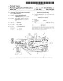
[0022] FIG. 1 is a schematic cross-section of a gas turbine engine;
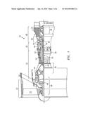
[0023] FIG. 2 is a partial longitudinal schematic sectional view of a combustor section according to one non-limiting embodiment that may be used with the gas turbine engine shown in FIG. 1;
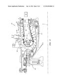
[0024] FIG. 3 is a perspective schematic sectional view a fuel injector system;
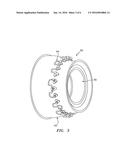
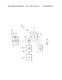
[0025] FIG. 4 is schematic sectional view of an aeration system according to one disclosed non-limiting embodiment;
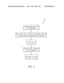
[0026] FIG. 5 is block diagram of operation of the aeration system; and
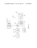
[0027] FIG. 6 is schematic sectional view of an aeration system according to another disclosed non-limiting embodiment.
DETAILED DESCRIPTION
[0028] FIG. 1 schematically illustrates a gas turbine engine 20. The gas turbine engine 20 is disclosed herein as a two-spool turbofan that generally incorporates a fan section 22, a compressor section 24, a combustor section 26 and a turbine section 28. Alternative engines might include an augmentor section (not shown) among other systems or features. The fan section 22 drives air along a bypass flowpath while the compressor section 24 drives air along a core flowpath for compression and communication into the combustor section 26 then expansion through the turbine section 28. Although depicted as a turbofan gas turbine engine in the disclosed non-limiting embodiment, it should be understood that the concepts described herein are not limited to use with turbofans as the teachings may be applied to other types of turbine engines such as a three-spool (plus fan) engine wherein an intermediate spool includes an intermediate pressure compressor (IPC) between the LPC and HPC and an intermediate pressure turbine (IPT) between the HPT and LPT.
[0029] The engine 20 generally includes a low spool 30 and a high spool 32 mounted for rotation about an engine central longitudinal axis A relative to an engine case structure 36 via several bearing structures 38. The low spool 30 generally includes an inner shaft 40 that interconnects a fan 42, a low pressure compressor ("LPC") 44 and a low pressure turbine ("LPT") 46. The inner shaft 40 drives the fan 42 directly or through a geared architecture 48 to drive the fan 42 at a lower speed than the low spool 30. An exemplary reduction transmission is an epicyclic transmission, namely a planetary or star gear system.
[0030] The high spool 32 includes an outer shaft 50 that interconnects a high pressure compressor ("HPC") 52 and high pressure turbine ("HPT") 54. A combustor 56 is arranged between the high pressure compressor 52 and the high pressure turbine 54. The inner shaft 40 and the outer shaft 50 are concentric and rotate about the engine central longitudinal axis A which is collinear with their longitudinal axes.
[0031] Core airflow is compressed by the low pressure compressor 44 then the HPC 52, mixed with the fuel and burned in the combustor 56, then expanded over the high pressure turbine 54 and low pressure turbine 46. The HPT 54 and LPT 46 rotationally drive the respective low spool 30 and high spool 32 in response to the expansion.
[0032] The main engine shafts 40, 50 are supported at a plurality of points by bearing structures 38 within the case structure 36. It should be understood that various bearing structures 38 at various locations may alternatively or additionally be provided.
[0033] In one non-limiting example, the gas turbine engine 20 is a high-bypass geared aircraft engine. In a further example, the gas turbine engine 20 bypass ratio is greater than about six (6:1). The geared architecture 48 can include an epicyclic gear train, such as a planetary gear system or other gear system. The example epicyclic gear train has a gear reduction ratio of greater than about 2.3, and in another example is greater than about 2.5:1. The geared turbofan enables operation of the low spool 30 at higher speeds which can increase the operational efficiency of the LPC 44 and LPT 46 and render increased pressure in a fewer number of stages.
[0034] A pressure ratio associated with the low pressure turbine 46 is pressure measured prior to the inlet of the low pressure turbine 46 as related to the pressure at the outlet of the LPT 46 prior to an exhaust nozzle of the gas turbine engine 20. In one non-limiting embodiment, the bypass ratio of the gas turbine engine 20 is greater than about ten (10:1), the fan diameter is significantly larger than that of the LPC 44, and the LPT 46 has a pressure ratio that is greater than about five (5:1). It should be understood, however, that the above parameters are only exemplary of one embodiment of a geared architecture engine and that the present disclosure is applicable to other gas turbine engines including direct drive turbofans.
[0035] In one embodiment, a significant amount of thrust is provided by the bypass flow due to the high bypass ratio. The fan section 22 of the gas turbine engine 20 is designed for a particular flight condition--typically cruise at about 0.8 Mach and about 35,000 feet. This flight condition, with the gas turbine engine 20 at its best fuel consumption, is also known as bucket cruise Thrust Specific Fuel Consumption (TSFC). TSFC is an industry standard parameter of fuel consumption per unit of thrust.
[0036] Fan Pressure Ratio is the pressure ratio across a blade of the fan section 22 without the use of a Fan Exit Guide Vane system. The low Fan Pressure Ratio according to one non-limiting embodiment of the example gas turbine engine 20 is less than 1.45. Low Corrected Fan Tip Speed is the actual fan tip speed divided by an industry standard temperature correction of "Tram"/518.70.5. The Low Corrected Fan Tip Speed according to one non-limiting embodiment of the example gas turbine engine 20 is less than about 1150 fps (351 m/s).
[0037] With reference to FIG. 2, the combustor 56 generally includes an outer liner 60, an inner liner 62 and a diffuser case module 64. The outer liner 60 and the inner liner 62 are spaced apart such that a combustion chamber 66 is defined therebetween. The combustion chamber 66 is generally annular in shape. The outer liner 60 is spaced radially inward from an outer diffuser case 65 of the diffuser case module 64 to define an annular outer plenum 76. The inner liner 62 is spaced radially outward from an inner diffuser case 67 of the diffuser case module 64 to define an annular inner plenum 78. It should be understood that although a particular combustor is illustrated, other combustor types with various combustor liner arrangements will also benefit herefrom. It should be further understood that the disclosed cooling flow paths are but an illustrated embodiment and should not be limited only thereto.
[0038] The liners 60, 62 contain the combustion products for direction toward the turbine section 28. Each liner 60, 62 generally includes a respective support shell 68, 70 which supports one or more heat shields 72, 74 which are attached to a hot side of the respective support shell 68, 70 with fasteners 75 such as with studs and nuts. In one disclosed non-limiting embodiment, the array includes a multiple of forward heat shields 72-1 and a multiple of aft heat shields 72-2 that passage the hot side of the outer support shell 68 and a multiple of forward heat shields 74-1 and a multiple of aft heat shields 74-2 that passage the hot side of the inner support shell 70.
[0039] The combustor 56 also includes a forward assembly 80 immediately downstream of the compressor section 24 to receive compressed airflow therefrom. The forward assembly 80 generally includes an annular hood 82, a bulkhead assembly 84, a multiple of fuel injectors 86 (one shown) and a multiple of fuel injector guides 90 (one shown). Each of the fuel injector guides 90 is circumferentially aligned with one of the hood ports 94 to project through the bulkhead assembly 84. Each bulkhead assembly 84 includes a bulkhead support shell 96 secured to the liners 60, 62, and a multiple of circumferentially distributed bulkhead heat shields 98 secured to the bulkhead support shell 96 around the central opening
[0040] The annular hood 82 extends radially between, and is secured to, the forwardmost ends of the liners 60, 62. The annular hood 82 includes a multiple of circumferentially distributed hood ports 94 that accommodate the respective fuel injector 86 and introduce air into the forward end of the combustion chamber 66 through a central opening. Each fuel injector 86 may be secured to the diffuser case module 64 and project through one of the hood ports 94 and through the central opening within the respective fuel injector guide 90.
[0041] The forward assembly 80 introduces core combustion air into the forward end of the combustion chamber 66 while the remainder enters the annular outer plenum 76 and the annular inner plenum 78. The multiple of fuel injectors 86 and surrounding structure generate a blended fuel-air mixture that supports combustion in the combustion chamber 66.
[0042] Opposite the forward assembly 80, the outer and inner support shells 68, 70 are mounted to a first row of Nozzle Guide Vanes (NGVs) 54A in the HPT 54. In one disclosed non-limiting embodiment, thirty-two (32) NGVs 54A are located immediately downstream of the combustor 56 as the first static vane structure upstream of a first turbine rotor in the turbine section 28. The NGVs 54A are static engine components which direct core airflow combustion gases onto the turbine blades of the first turbine rotor in the turbine section 28 to facilitate the conversion of pressure energy into kinetic energy. The core airflow combustion gases are also accelerated by the NGVs 54A because of their convergent shape and are typically given a "spin" or a "swirl" in the direction of turbine rotor rotation. The turbine rotor blades absorb this energy to drive the turbine rotor at high speed.
[0043] With reference to FIG. 3, a fuel injector system 90 generally includes one or more fuel injector supply manifolds 94 from which a multiple of fuel injectors 86 extend. The fuel injector supply manifolds 94 are located circumferentially around a diffuser case module 64 to communicate fuel to the multiple of fuel injectors 86 to inject fuel under pressure into the combustor 56 for ignition. It should be appreciated that various fuel injector systems 90 will benefit herefrom.
[0044] With reference to FIG. 4, the fuel injector system 90 includes one or more aeration systems 96. The aeration system 96 may be utilized for the entire fuel injector system 90, each or subsets of fuel injectors 86 and/or for each fuel circuit in a staged combustion system. That is, the fuel injector system 90 may include primary, secondary and further fuel circuits to provide a staged combustion and each circuit may include a separate aeration system 96 to provide pressurized gas at engine start/restart.
[0045] The aeration system 96 includes an air tank 98 in communication with, in one disclosed on-limiting embodiment, the high pressure compressor 52 which supplies high-pressure air to charge the air tank 98. The air tank 98 may be a cylinder or small volume that is replenished either when the engine is running or by a source external to the aircraft when on the ground. The air tank 98 may not be initially charged by the high pressure compressor 52 as minimal pressure is available therefrom at engine start-up. The air, once in the high pressure compressor 52, is at the temperature of the high pressure compressor 52.
[0046] The air tank 98 is in communication with each or a subset of the multiple of fuel injectors 86 through a valve 100. The valve 100 may be an on-off type in communication with a control subsystem 102 that generally includes a control module 104 that executes aerating supply logic 106 (FIG. 5). The functions of the logic 106 are disclosed in terms of functional block diagrams, and it should be understood by those skilled in the art with the benefit of this disclosure that these functions may be enacted in either dedicated hardware circuitry or programmed software routines capable of execution in a microprocessor based electronics control embodiment. In one non-limiting embodiment, the control module 104 may be a portion of a flight control computer, a portion of a Full Authority Digital Engine Control (FADEC), a stand-alone unit or other system.
[0047] The control module 104 typically includes a processor 104A, a memory 104B, and an interface 104C. The processor 104A may be any type of known microprocessor having desired performance characteristics. The memory 104B may be any computer readable medium which stores data and control algorithms such as logic 106 as described herein. The interface 104C facilitates communication with other components such as the valve 100. It should be appreciated that various other components such as sensors, actuators and other subsystems may be utilized herewith.
[0048] Mixing of the high pressure air with each or subsets of fuel injectors 86 occurs in one disclosed non-limiting embodiment, at the nozzle 108 of the fuel injector 86 or in a mixing chamber 110 (FIG. 6) upstream of the nozzle 108. Fuel-Air mixing at each or subsets of the fuel injectors 86 eliminate or minimizes the requirement for pilot fuel injectors and/or pilot fuel circuits which reduces the complexity and/or number of fuel supply manifolds.
[0049] In operation, as the engine spools up, the control subsystem 102 opens the valve 100 to release high-pressure air from within the air tank 98 to mix the high pressure air with each or subsets of fuel injectors 86. The fuel and pressurized gas can be mixed at the nozzle 108 (FIG. 4) of the fuel injector 86 or in the mixing chamber 110 (FIG. 6) upstream of the nozzle 108. The aeration system 96 produces a more finely atomized spray than fuel alone to thereby facilitate engine start/restart. Once the engine 20 is running, the valve 100 is closed and the fuel feed rate is increased to operational speed.
[0050] Utilization of the relatively cool, high-pressure air from the air tank 98 assures effective mixture and burn of the fuel as well as provide air at a higher pressure than the fuel system. Also, the relatively cool high-pressure air from the air tank 98 contributes to the combustion process.
[0051] It should be understood that relative positional terms such as "forward," "aft," "upper," "lower," "above," "below," and the like are with reference to the normal operational attitude and should not be considered otherwise limiting.
[0052] It should be understood that like reference numerals identify corresponding or similar elements throughout the several drawings. It should also be understood that although a particular component arrangement is disclosed in the illustrated embodiment, other arrangements will benefit herefrom.
[0053] Although particular step sequences are shown, described, and claimed, it should be understood that steps may be performed in any order, separated or combined unless otherwise indicated and will still benefit from the present disclosure.
[0054] The foregoing description is exemplary rather than defined by the limitations within. Various non-limiting embodiments are disclosed herein, however, one of ordinary skill in the art would recognize that various modifications and variations in light of the above teachings will fall within the scope of the appended claims. It is therefore to be understood that within the scope of the appended claims, the disclosure may be practiced other than as specifically described. For that reason the appended claims should be studied to determine true scope and content.
User Contributions:
Comment about this patent or add new information about this topic:
Images included with this patent application:
 |  |
 |  |
 |  |
 |
| Similar patent applications: | |
| Date | Title |
|---|---|
| 2015-12-24 | Serpentine baffle for a gas turbine engine exhaust duct |
| 2016-02-25 | Apparatus and methods for lipidic cubic phase (lcp) injection for membrane protein investigations |
| 2016-01-07 | Variable area nozzle for gas turbine engine |
| 2016-01-14 | Variable nozzle for aeronautic gas turbine engine |
| 2016-02-18 | Device for controlling the supply of a fluid to a system allowing fluid consumption to be optimised |
| New patent applications in this class: | |
| Date | Title |
|---|---|
| 2019-05-16 | A fuel injector with an idle stroke |
| 2016-12-29 | Fuel injection rate modulation by magnetostrictive actuator and fluidomechanical coupler |
| 2016-06-23 | Fuel injector for common rail |
| 2016-06-09 | Two step metering solenoid for multi-physics fuel atomizer |
| 2016-06-02 | Fuel injector |
| Top Inventors for class "Fluid sprinkling, spraying, and diffusing" | |
| Rank | Inventor's name |
|---|---|
| 1 | Huasong Zhou |
| 2 | Jianmin Chen |
| 3 | Carl L.c. Kah, Jr. |
| 4 | Samuel C. Walker |
| 5 | Mauro Grandi |