Patent application title: Petroleum Desalting Utilizing Voltage Modulation
Inventors:
IPC8 Class: AB03C1100FI
USPC Class:
204672
Class name: Apparatus apparatus for electrical (including simultaneous electrical and magnetic) separation or purification of liquid or magnetic treatment of liquid (other than separation) parallel plate-type electrodes
Publication date: 2016-01-14
Patent application number: 20160008823
Abstract:
A method of removing entrained salt containing water from an inlet crude
oil stream includes the steps of applying an electrical energy to at
least one electrode of a plurality of horizontally oriented, spaced-apart
electrodes (12, 14, 16) housed within an elongated desalting vessel (10)
and distributing an inlet crude oil stream between the electrodes. Each
electrode in the plurality of electrodes is housed in an upper portion of
the desalting vessel and may be in communication with a first, second and
third transformer (42, 44, 46), respectively. The electrical energy may
be at a single frequency and voltage or at a modulated voltage. Or, the
electrical energy may be a modulated frequency at a single or modulated
voltage. Fresh water may be mixed with the inlet crude oil stream either
exteriorly or interiorly of the vessel.Claims:
1. An elongated horizontal vessel comprising: a lower, an upper, and a
middle electrode, each electrode oriented in a horizontal plane and
sharing a same vertical plane; at least one transformer in communication
with at least one of the lower, upper and middle electrodes; a vertically
oriented pipe in communication with a crude oil stream inlet; the at
least one transformer providing an electrical energy having a frequency
greater than 60 Hz; the vertically oriented pipe having means for
horizontally distributing a crude oil stream between the lower and middle
electrode and the middle and upper electrode.
2. An elongated horizontal vessel according to claim 1 further comprising a fresh water inlet in communication with a crude oil stream inlet.
Description:
CROSS-REFERENCE TO RELATED APPLICATIONS
[0001] This application is a divisional application which claims priority to U.S. patent application Ser. No. 13/812,979 filed on Jan. 29, 2013, which claims priority to United States National Phase of PCT Patent Application No. US2011/046713 filed on Aug. 5, 2011, which claims priority to U.S. Provisional Patent Application No. 61/371,046 filed Aug. 5, 2010, all of which are incorporated herein by reference.
BACKGROUND OF THE INVENTION
[0002] This invention relates generally to crude oil desalter/dehydrator vessels and, more specifically, to desalter/dehydrator vessels which utilize a set of electrodes.
[0003] A common crude oil desalter/dehydrator used by many of the world's refiners was invented by Petreco in 1980 and is illustrated and described in U.S. Pat. Nos. 4,149,958; 4,182,672; 4,188,277 and 4,209,374 ("the Petreco patents.") Desalters/dehydrators marketed under the Petreco patents have been referred to as BILECTRIC® desalters (hereinafter "bilectric desalter"). A bilectric desalter utilizes a set of two or three parallel electrodes arranged horizontally in a horizontal vessel. After the crude oil containing salt is prepared by adding fresh water, the oil-water mixture is introduced horizontally into the vessel and between these electrodes. This technique of desalting coalesces the dispersed water in an intense electrostatic field and has the advantage of achieving rapid and highly efficient droplet coalescence and separation.
[0004] Historically, a bilectric desalter utilizes two or three AC power units (transformers) designed to operate at a single voltage. Each power unit is connected to a separate, horizontally oriented electrode. The power unit on the lowest electrode establishes an AC electrostatic field between the oil/water interface and the energized electrode. This lowest electrode is intended to provide sufficient voltage to diminish and control the formation of a "rag" layer at the oil/water interface. If the applied voltage is not an effective one, the interface rag can accumulate which, in turn, places a greater power demand on the power unit. This effectively reduces the applied voltage and results in a less effective process to control the rag.
[0005] The middle (or upper) electrode establishes an electrostatic field between itself and the lowest electrode. This electrostatic field remains effective unless the rag layer intrudes into the zone between the electrodes and compromises the applied voltage. Finally, the upper electrode establishes an electrostatic field between the middle electrode and itself. The performance of this field is rarely compromised by the formation of an interface rag.
[0006] When an interface rag consisting of an unresolved oil/water emulsion accumulates on the oil/water interface, the interface rage hinders the strength of the electrostatic field which, in turn, leads to water chaining and shorting of the electrodes. To avoid the detrimental effects of water chaining, the AC voltage may need to be reduced. This reduction in voltage further compromises the bilectric desalter's ability to promote decay of the rag layer. The strength of the AC electrostatic field also limits the entrained water content to no more than 10%. When the water content increases above 10% the water droplets chain together and promote a shorting of the electrostatic fields.
[0007] As crudes become heavier and more difficult to desalt and dehydrate, they tend to form rag layers that are more stable and less likely to collapse in the presence of an electrostatic field. These "rag-producing" oils compromise the overall dehydration and desalting performance of the bilectric desalter.
SUMMARY OF THE INVENTION
[0008] A method of removing entrained salt containing water from an inlet crude oil stream includes the steps of (1) applying a voltage and frequency to one or more horizontally oriented, spaced-apart electrodes housed within an elongated vessel and (2) exposing the inlet crude oil stream entering the vessel to the electric field being reduced. As illustrated in the 2×2 matrix below, four different configurations of frequency and voltage (I to IV below) can be applied to the one or more electrodes.
TABLE-US-00001 Voltage Modulated II I Single, steady III IV Single (>60 Hz) Variable or modulating Frequency
[0009] Each electrode in the plurality of electrodes is housed in an upper portion of the vessel and at least one of the electrodes is in communication with a transformer. The transformer may provide a multiple frequency electrical energy to its respective electrode. Fresh water may be mixed with the inlet crude oil stream either exteriorly or interiorly of the vessel. The vessel may include a mud wash system of a kind known in the art and located in its lower portion.
[0010] The use of a modulating, high frequency AC field can increase the energy available to control or prevent the formation of the rag layer and re-establish the desalting and dehydration performance of a bilectric desalter. Using one to three modulating, high frequency power units, the electrostatic strength can be optimized to promote maximum rag collapse and water droplet growth. Furthermore, because a modulating voltage field promotes effective coalescence in crude oil with very little entrained water (<3%), it achieves a significantly greater coalescence with crude oil containing up to 10% BS&W (known as basic sediment and water). Also, modulated fields handle entrained water cuts significantly greater than 10%, thereby permitting the use of more water so the removal of entrained salt is improved.
[0011] Objects of this invention are to provide an improved system and method for removing entrained salt containing water from a heavy crude oil stream that supplies an effective electrostatic field for treating these heavy crude oils while at the same time preventing rag layer formation, controlling and stabilizing any formed rag-layer, and avoiding water chaining and shorting of the electrodes.
BRIEF DESCRIPTION OF THE DRAWINGS
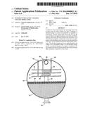
[0012] FIG. 1 is a cross-sectional view of an elongated horizontal vessel of the type that can be used to practice the systems and methods of this invention. The elongated vessel 10 has three spaced-apart horizontal electrodes identified by the numbers 12, 14 and 16. Voltages are applied to the three electrodes by conductors 18, 20 and 22 extending exteriorly of vessel 10.
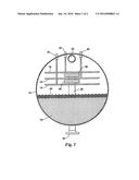
[0013] FIG. 2 shows a system and method that employs the basic concepts of the system of FIG. 1. The system of FIG. 2 includes an elongated horizontal vessel 10 having lower, middle and upper electrodes 12, 14 and 16 supplied with electrical energy by conductors 18, 20 and 22, a crude oil inlet 24 with vertical pipes 26 each having horizontal liquid outlets 29 and 30, an outlet collector 32 and salt containing water 34 collected in the bottom of the vessel 10. The essential difference between the method of FIG. 1 and FIG. 2 is in the method of FIG. 1, the salt is removed from the crude oil by electrostatic dehydration without the use of fresh water whereas in FIG. 2 fresh water is mixed with the salty crude prior to the crude oil entering vessel 10.
TABLE-US-00002 LISTING OF ELEMENTS USED IN THE DRAWINGS AND DETAILED DESCRIPTION 10 Vessel 12 Lower electrode 14 Middle electrode 16 Upper electrode 18 Conductor in communication with 12 20 Conductor in communication with 14 22 Conductor in communication with 16 24 Crude oil inlet 25 Horizontal distributor pipe 26 Vertical distributor pipe 27 Inlet valve 28 Pump 29 Horizontal liquid outlet 30 Horizontal liquid outlet 32 Outlet collector 33 Crude oil discharge 34 Salt containing water 42 Transformer in communication with 18 44 Transformer in communication with 20 46 Transformer in communication with 22 48 Rag layer 50 Fresh water inlet pipe 54 Opening 56 Water outlet pipe 58 Control valve 60 Level control 62 Mud wash pipe
DETAILED DESCRIPTION OF THE PREFERRED EMBODIMENTS
[0014] Referring first to FIG. 1, in one method of practicing this invention, fresh water is mixed with salty crude exteriorly of vessel 10. A crude oil inlet 24 connects through an inlet valve 27 (see FIG. 2) to vertical pipes 26 that have horizontally discharging liquid outlets 28 and 30. Crude oil, having excessive salt therein, typically in the form of salt water, is passed upwardly from inlet 24 through pipes 26 and is horizontally discharged through outlets 28 and 30 to thereby spread the incoming crude oil and water mixture between electrodes 12 and 14 and 14 and 16, respectively. By means of electrostatic voltages applied to electrodes 12, 14 and 16, salt containing water 34 is condensed out of the crude oil within the vessel 10 and settles to the bottom of the vessel 10. The crude oil having water substantially removed passes out of the vessel through outlet collector 32 and crude oil discharge 33. Not shown in FIG. 1 is a water outlet discharge control system, such as can be provided by a float or level control system.
[0015] Referring now to FIG. 2, in another method of practicing this invention, fresh water passing through fresh water inlet pipe 50 is mixed with crude oil before the crude oil enters vessel 10 through crude oil inlet 24. The fresh water dilutes salt from the crude oil, forming salt containing water 34 that tends to settle to the bottom of vessel 10. By means of a level control system (not shown), a level of salt containing water 34 is maintained in the vessel while the crude oil, substantially free of salt, exits the vessel through outlet collector 32 and crude oil discharge 33.
[0016] The system of FIG. 2 includes an elongated horizontal vessel 10 having therein lower, middle and upper electrodes 12, 14 and 16 supplied with electrical energy by conductors 18, 20 and 22; a crude oil inlet 24 with vertical pipes 26 each having horizontal liquid outlets 29 and 30; an outlet collector 3; and salt containing water 34 collected in the bottom of the vessel, all as illustrated and described with reference to FIG. 1.
[0017] In the system of FIG. 2, salt containing crude oil is delivered to vessel 10 through crude oil inlet pipe 24. Fresh water is conveyed into vessel 10 through a fresh water inlet pipe 50. The mixed crude oil and fresh water passes through mix valve 27 into the interior of vessel 10 through horizontal distributor pipes 25, into vertical distributor pipes 26 and through a plurality of lower and upper liquid outlets 29 and 30. Salt from the crude oil is diluted into the fresh water thereby forming salt water mixed with the crude oil from which salt has been at least substantially removed. The mixed crude oil and fresh water is subjected to electrostatic fields supplied on electrodes 12, 14 and 16. The electric fields augment separation of the crude oil and water, the salt containing water 34 settling to the lower portion of vessel 10 and the crude oil rising to the upper portion. The crude oil floating on the water layer 34 forms a rag layer 48 which consists of an unresolved oil and water mixture. Rag layer 48 separates the water 34 within the vessel from the crude oil.
[0018] Salt contained in the crude oil delivered into pipe 24 is contacted and diluted in the resulting water passing into the vessel through pipe 50. The salt containing water 34 is then separated from the crude oil by electrostatic actions within the upper portion of the vessel, the electrostatic action being provided by electrodes 12, 14 and 16. The crude oil, having at least a significant portion of salt removed, collects in the upper portion of the vessel and exits the vessel through outlet collector 32 from which the reduced salt content crude oil can be conveyed for refining.
[0019] Water is collected into the lower portion of vessel 10 from two sources. The first is salt water normally contained in crude oil that enters crude oil inlet 24. The second is fresh water flowing into the vessel through inlet 50. Water leaves vessel 10 through an opening 54 communicating with a water discharge pipe 56. A control valve 58 operated by a level control 60 maintains the height of the water interface within the vessel indicated by the level of rag layer 48.
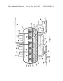
[0020] The desalter shown in FIG. 2 includes a system of keeping vessel 10 free from the accumulation of solids that in the petroleum industry is frequently called "mud." For this purpose the desalter system of FIG. 2 includes a mud wash system that utilizes a horizontal perforated, mud wash pipe 62 laying on or adjacent the interior bottom of tank 10. One end of perforated mud wash pipe 62 is connected to the outlets of pump 28 by mud wash piping 40 while the intake of pump 28 is connected to water discharge or outlet pipe 56. Thus pump 28 circulates salt containing water 34 to stir up and carry with it mud that settles to the bottom of tank 10. At the same time salt containing water is discharged through control valve 58 and away from the system through water outlet pipe 56.
[0021] The essential difference between the system and method of FIG. 1 and that of FIG. 2 is that in the system and method of FIG. 1, the salt is removed from the crude oil by electrostatic dehydration without the use of fresh water whereas in FIG. 2 fresh water is mixed with the salty crude prior to the crude oil entering vessel 10. In both systems the mixed crude oil and fresh water are subjected to electric fields within the vessel to cause the salt water to separate from the crude oil by the means of the imposition of electrical charges on electrodes 12, 14 and 16.
[0022] Illustrated in FIG. 2 are transformers 42, 44 and 46 having conductors 18, 20 and 22 that transfer voltages to electrodes 12, 14 and 16. In the practice of this invention, transformers 18, 20 and 22 provide multiple frequency electrical energy (see quadrants Ito IV in table below) to electrodes 12, 14 and 16 that substantially improves the electrostatic separation of the water contained in the crude oil from the crude oil itself. The concept of utilizing dual frequency electrostatic coalescence is described in detail in U.S. Pat. Nos. 6,860,979 and 7,351,320, which are hereby incorporated by reference. As a result of improved electrostatic coalescence achieved by the unique voltages provided by transformers 42, 44 and 46, separation of salt water from the crude oil is substantially enhanced and thereby salt is more effectively removed from the crude oil. As illustrated in the 2×2 matrix below, four different configurations of frequency and voltage (I to IV below) can be applied to the one or more electrodes. Preferably, vessel 10 makes use of the configurations of quadrants II and III.
TABLE-US-00003 Voltage Modulated II I Single, steady III IV Single (>60 Hz) Variable or modulating Frequency
[0023] As previously mentioned, a problem encountered in desalters of the type that employ electrostatic separation is the formation of rag that is indicated by the numeral 48 in FIG. 2. If the applied voltage in the system is not effective the interface rag 48 can accumulate and impose more demands upon the power units. By the system of this invention wherein multiple frequency electrostatic coalescence is employed, the detrimental effects of the occurrence of interface rag is substantially reduced.
[0024] While the invention has been described with a certain degree of particularity, it is manifest that many changes may be made in the details of construction and the arrangement of components without departing from the spirit and scope of this disclosure. It is understood that the invention is not limited to the embodiments set forth herein for purposes of exemplification, but is limited only by the scope of the attached claims, including the full range of equivalency to which each element thereof is entitled.
User Contributions:
Comment about this patent or add new information about this topic:
Images included with this patent application:
 |  |
 |
| Similar patent applications: | |
| Date | Title |
|---|---|
| 2016-05-26 | Method of detecting and quantifying perchlorate contamination |
| 2016-04-07 | Processes for desalting crude oil under dynamic flow conditions |
| 2016-04-21 | Method of distributing current in electrodeposition process |
| 2016-05-05 | Photoelectrochemical assay apparatus for determining chemical oxygen demand |
| 2015-11-26 | Glycan profiling utilizing capillary electrophoresis |
| New patent applications in this class: | |
| Date | Title |
|---|---|
| 2016-12-29 | Portable electronic water disinfection device with replaceable treatment cartridges |
| 2016-06-23 | Cdi type water treatment apparatus |
| 2014-08-28 | Apparatus and method for removal of ions |
| 2013-04-04 | Apparatus for removal of ions, and a method of manufacturing an apparatus for removal of ions from water |
| 2010-06-10 | Electrode for capacitive deionization, capacitive deionization device and electric double layer capacitor including the electrode |
| Top Inventors for class "Chemistry: electrical and wave energy" | |
| Rank | Inventor's name |
|---|---|
| 1 | Vamsee K. Pamula |
| 2 | Michael G. Pollack |
| 3 | Adam Heller |
| 4 | Vijay Srinivasan |
| 5 | Li-Shiang Liang |