Patent application title: TED HEAT EXCHANGER
Inventors:
Man Ju Oh (Yongin-Si, KR)
Man Ju Oh (Yongin-Si, KR)
Jae Woong Kim (Hwaseong-Si, KR)
Jae Woong Kim (Hwaseong-Si, KR)
Jae Woo Park (Ansan-Si, KR)
Jae Woo Park (Ansan-Si, KR)
Jae-Hoon Kim (Cheonan-Si, KR)
Jae-Hoon Kim (Cheonan-Si, KR)
Assignees:
Hyundai Motor Company
IPC8 Class: AF25B2104FI
USPC Class:
62 33
Class name: Using electrical or magnetic effect thermoelectric; e.g., peltier effect heat pump, selective heating and cooling
Publication date: 2016-01-07
Patent application number: 20160003501
Abstract:
A thermo-electric device heat exchanger may include a plate part
including a plurality of cooling tubes and a plurality of heat radiation
tubes alternately disposed with respect to each other, a cooling
inflowing tank and a cooling discharging tank connected to an inlet and
an outlet of a cooling tube in the plurality of cooling tubes, a heat
radiation inflowing tank and a heat radiation discharging tank connected
to an inlet and an outlet of a heat radiation tube in the plurality of
radiation tubes, and a thermoelectric element having a cooling surface
and a heat radiation surface and disposed between the cooling tube and
the heat radiation tube. The cooling surface may be attached to the
cooling tube and the heat radiation surface may be attached to the heat
radiation tube.Claims:
1. A thermo-electric device (TED) heat exchanger, comprising: a plate
part configured to include a plurality of cooling tubes and a plurality
of heat radiation tubes alternately disposed with respect to each other,
wherein one or more cooling tubes and one or more heat radiation tubes
are formed in a tube shape having fluid passages formed therein; a
cooling inflowing tank and a cooling discharging tank configured to be
connected to an inlet and an outlet of a cooling tube in the plurality of
cooling tubes, respectively; a heat radiation inflowing tank and a heat
radiation discharging tank configured to be connected to an inlet and an
outlet of a heat radiation tube in the plurality of radiation tubes,
respectively; and a thermoelectric element configured to have a cooling
surface and a heat radiation surface and be disposed between the cooling
tube and the heat radiation tube, the cooling surface being attached to
the cooling tube and the heat radiation surface being attached to the
heat radiation tube.
2. The TED heat exchanger according to claim 1, wherein the inlet and the outlet of the cooling tube are disposed at opposite sides with respect to a center line extended to a longitudinal direction of the cooling tube.
3. The TED heat exchanger according to claim 1, wherein the inlet and the outlet of the heat radiation tube are disposed at opposite sides with respect to a center line extended to a longitudinal direction of the heat radiation tube.
4. The TED heat exchanger according to claim 1, wherein: the inlet of the cooling tube and the outlet of the heat radiation tube are disposed at opposite sides, with respect to a center line extended to a longitudinal direction of the cooling tube or with respect to a center line extended to a longitudinal direction of the heat radiation tube; and the outlet of the cooling tube and the inlet of the heat radiation tube are disposed at opposite sides, with respect to the center line extended to the longitudinal direction of the cooling tube or with respect to the center line extended to the longitudinal direction of the heat radiation tube.
5. The TED heat exchanger according to claim 4, wherein: the cooling inflowing tank and the heat radiation discharging tank are adjacently disposed at opposite sides, with respect to the center line extended to the longitudinal direction of the cooling tube or with respect to the center line extended to the longitudinal direction of the heat radiation tube; the cooling discharging tank and the heat radiation inflowing tank are adjacently disposed at opposite sides, with respect to the center line extended to the longitudinal direction of the cooling tube or with respect to the center line extended to the longitudinal direction of the heat radiation tube; the cooling inflowing tank and the cooling discharging tank are connected to the inlet and outlet of the cooling tube, respectively; and the heat radiation inflowing tank and the heat radiation discharging tank are connected to the inlet and outlet of the heat radiation tube, respectively.
6. The TED heat exchanger according to claim 1, wherein all inlets of the plurality of heat radiation tubes are connected to the heat radiation inflowing tank.
7. The TED heat exchanger according to claim 1, wherein all outlets of the plurality of heat radiation tubes are connected to the heat radiation discharging tank.
8. The TED heat exchanger according to claim 1, wherein inlets of a first set of cooling tubes in the plurality of cooling tubes and outlets of a second set of cooling tubes in the plurality of cooling tubes communicate with each other through the cooling inflowing tank or the cooling discharging tank, thereby forming a series of continuous channels.
9. The TED heat exchanger according to claim 1, wherein the plurality of cooling tubes are divided into a first cooling set having a fluid flow in one side and a second cooling set having a fluid flow in the other side, the first cooling set and the second cooling set being configured to have an inlet and an outlet disposed in an opposite direction to each other.
10. The TED heat exchanger according to claim 9, wherein the inlet of the first cooling set communicates with the outlet of the second cooling set in the cooling inflowing tank or the cooling discharging tank, or the outlet of the first cooling set communicates with the inlet of the second cooling set in the cooling inflowing tank or the cooling discharging tank.
11. The TED heat exchanger according to claim 10, wherein: in a case where the inlet of the first or second cooling set is an inlet in which the fluid first flows, the inlet of the first or second cooling set does not communicate with the outlet of the other set; and in a case where the outlet of the first or second cooling set is an outlet through which the fluid is finally discharged, the outlet of the first or second cooling set does not communicate with the inlet of the other set.
12. The TED heat exchanger according to claim 11, wherein: the cooling inflowing tank and the cooling discharging tank are each connected to ends of the plurality of cooling tubes; and insides of the cooling inflowing tank and the cooling discharging tank are provided with partition walls to form a zigzag channel through which the fluid continuously flows in the first cooling set and the second cooling set.
Description:
CROSS REFERENCE TO RELATED APPLICATION
[0001] The present application claims priority of Korean Patent Application Number 10-2014-0084565, filed Jul. 7, 2014, the entire contents of which application are incorporated herein for all purposes by this reference.
BACKGROUND OF INVENTION
[0002] 1. Field of Invention
[0003] The present invention relates to a new Thermo-Electric Device (TED) heat exchanger capable of increasing cooling performance and heat radiation performance.
[0004] 2. Description of Related Art
[0005] A thermoelectric element is configured to include a cooling surface and a heat radiation surface and thus may generate a temperature difference between the cooling surface and the heat radiation surface due to an electrical signal. Further, when polarities of electricity are changed, a role of the cooling surface and the heat radiation surface is changed.
[0006] Recently, various concepts for a heat exchanger using the thermoelectric element have been proposed; however, they are less likely to support performance of the heat exchanger itself over convenience of the thermoelectric element and simplification of a system.
[0007] That is, the thermoelectric element needs to sufficiently radiate heat to secure the cooling performance. However, the thermoelectric element has a limitation in the heat radiation performance, and therefore does not have the sufficient cooling performance compared to power usage.
[0008] The information disclosed in this Background section is only for enhancement of understanding of the general background of the invention and should not be taken as an acknowledgement or any form of suggestion that this information forms the prior art already known to a person skilled in the art.
SUMMARY OF INVENTION
[0009] The present invention is to provide a new TED heat exchanger capable of increasing cooling performance and heat radiation performance.
[0010] According to various aspects of the present invention, there is provided a TED heat exchanger, including: a plate part configured to include a plurality of cooling tubes and a plurality of heat radiation tubes alternately disposed with respect to each other, wherein one or more cooling tubes and one or more heat radiation tubes are formed in a tube shape having fluid passages formed therein; a cooling inflowing tank and a cooling discharging tank configured to be connected to an inlet and an outlet of a cooling tube in the plurality of cooling tubes, respectively; a heat radiation inflowing tank and a heat radiation discharging tank configured to be connected to an inlet and an outlet of a heat radiation tube in the plurality of radiation tubes, respectively; and a thermoelectric element configured to have a cooling surface and a heat radiation surface and be disposed between the cooling tube and the heat radiation tube, the cooling surface being attached to the cooling tube and the heat radiation surface being attached to the heat radiation tube.
[0011] The inlet and the outlet of the cooling tube may be disposed at opposite sides with respect to a center line extended to a longitudinal direction of the cooling tube. The inlet and the outlet of the heat radiation tube may be disposed at opposite sides with respect to a center line extended to a longitudinal direction of the heat radiation tube.
[0012] The inlet of the cooling tube and the outlet of the heat radiation tube may be disposed at opposite sides, with respect to a center line extended to a longitudinal direction of the cooling tube or with respect to a center line extended to a longitudinal direction of the heat radiation tube. The outlet of the cooling tube and the inlet of the heat radiation tube may be disposed at opposite sides, with respect to the center line extended to the longitudinal direction of the cooling tube or with respect to the center line extended to the longitudinal direction of the heat radiation tube.
[0013] The cooling inflowing tank and the heat radiation discharging tank may be adjacently disposed at opposite sides, with respect to the center line extended to the longitudinal direction of the cooling tube or with respect to the center line extended to the longitudinal direction of the heat radiation tube. The cooling discharging tank and the heat radiation inflowing tank may be adjacently disposed at opposite sides, with respect to the center line extended to the longitudinal direction of the cooling tube or with respect to the center line extended to the longitudinal direction of the heat radiation tube. The cooling inflowing tank and the cooling discharging tank may be connected to the inlet and outlet of the cooling tube, respectively. The heat radiation inflowing tank and the heat radiation discharging tank may be connected to the inlet and outlet of the heat radiation tube, respectively.
[0014] All inlets of the plurality of heat radiation tubes may be connected to the heat radiation inflowing tank. All outlets of the plurality of heat radiation tubes may be connected to the heat radiation discharging tank.
[0015] Inlets of a first set of cooling tubes in the plurality of cooling tubes and outlets of a second set of cooling tubes in the plurality of cooling tubes may communicate with each other through the cooling inflowing tank or the cooling discharging tank, thereby forming a series of continuous channels.
[0016] The plurality of cooling tubes may be divided into a first cooling set having a fluid flow in one side and a second cooling set having a fluid flow in the other side, in which the first cooling set and the second cooling set may be configured to have an inlet and an outlet disposed in an opposite direction to each other.
[0017] The inlet of the first cooling set may communicate with the outlet of the second cooling set in the cooling inflowing tank or the cooling discharging tank, or the outlet of the first cooling set may communicate with the inlet of the second cooling set in the cooling inflowing tank or the cooling discharging tank.
[0018] In a case where the inlet of the first or second cooling set is an inlet in which the fluid first flows, the inlet of the first or second cooling set may not communicate with the outlet of the other set. In a case where the outlet of the first or second cooling set is an outlet through which the fluid is finally discharged, the outlet of the first or second cooling set may not communicate with the inlet of the other set.
[0019] The cooling inflowing tank and the cooling discharging tank may be each connected to ends of the plurality of cooling tubes, and insides of the cooling inflowing tank and the cooling discharging tank may be provided with partition walls to form a zigzag channel through which the fluid continuously flows in the first cooling set and the second cooling set.
[0020] The methods and apparatuses of the present invention have other features and advantages which will be apparent from or are set forth in more detail in the accompanying drawings, which are incorporated herein, and the following Detailed Description, which together serve to explain certain principles of the present invention.
BRIEF DESCRIPTION OF THE DRAWINGS
[0021] The above and other objects, features and advantages of the present invention will be more clearly understood from the following detailed description taken in conjunction with the accompanying drawings, in which:
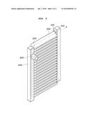
[0022] FIG. 1 is a perspective view of an exemplary TED heat exchanger according to the present invention;
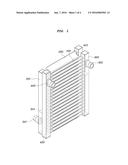
[0023] FIG. 2 is a diagram illustrating a cooling side of an exemplary TED heat exchanger according to the present invention;
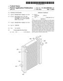
[0024] FIG. 3 is a diagram illustrating a heat radiation side of an exemplary TED heat exchanger according to the present invention; and
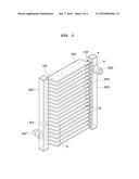
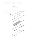
[0025] FIG. 4 is a diagram illustrating a tube and a thermoelectric element of an exemplary TED heat exchanger according to the present invention.
DETAILED DESCRIPTION
[0026] Reference will now be made in detail to various embodiments of the present invention(s), examples of which are illustrated in the accompanying drawings and described below. While the invention(s) will be described in conjunction with exemplary embodiments, it will be understood that present description is not intended to limit the invention(s) to those exemplary embodiments. On the contrary, the invention(s) is/are intended to cover not only the exemplary embodiments, but also various alternatives, modifications, equivalents and other embodiments, which may be included within the spirit and scope of the invention as defined by the appended claims.
[0027] FIG. 1 is a perspective view of a TED heat exchanger, FIG. 2 is a diagram illustrating a cooling side of a TED heat exchanger, FIG. 3 is a diagram illustrating a heat radiation side of a TED heat exchanger, and FIG. 4 is a diagram illustrating a tube and a thermoelectric element of a TED heat exchanger, according to various embodiments of the present invention.
[0028] The TED heat exchanger according to various embodiments includes: a plate part configured to have a cooling tube 100 and a heat radiation tube 200 which are formed in a tube shape having fluid passages formed therein, in which the cooling tube 100 and the heat radiation tube 200 are prepared in plural and continuously disposed and the cooling tubes 100 and the heat radiation tubes 200 are alternately disposed to each other; a cooling inflowing tank 310 and a cooling discharging tank 320 configured to be connected to an inlet and an outlet of the cooling tube 100, respectively; a heat radiation inflowing tank 410 and a heat radiation discharging tank 420 configured to be connected to an inlet and an outlet of the heat radiation tube 200, respectively; and a thermoelectric element 500 configured to have a cooling surface and a heat radiation surface and be disposed between the cooling tube 100 and the heat radiation tube 200, in which the cooling surface is attached to the cooling tube 100 and the heat radiation surface is attached to the heat radiation tube 200.
[0029] FIG. 4 illustrates the tube and the thermoelectric element, in which the plate part according to the exemplary embodiment of the present invention is configured of a plurality of the tubes which may be classified into the cooling tube 100 and the heat radiation tube 200. Each tube is formed in the tube shape which has the fluid passages formed therein and as illustrated in FIG. 4, a pair of upper and lower plates 10 is coupled with each other to form an inner space, in which the inner space is provided with pins 20 which are heat-exchanged with a fluid and the pins 20 may be coupled with each other by a brazing method, and the like.
[0030] Meanwhile, as illustrated in FIGS. 2 and 3, the cooling tube 100 and the heat radiation tube 200 are each prepared in plural and continuously disposed. Further, in the overall state in which the cooling tubes 100 and the heat radiation tubes 200 are coupled with each other as illustrated in FIG. 1, the cooling tubes 100 and the heat radiation tubes 200 are alternately disposed to each other.
[0031] As illustrated in FIG. 4, the thermoelectric element 500 is disposed between the cooling tube 100 and the heat radiation tube 200 which are alternately disposed to each other. In FIG. 1, the thermoelectric element is covered and thus is not illustrated, but it may be understood from FIG. 4 that the thermoelectric element 500 is disposed between the cooling tube 100 and the heat radiation tube 200. Further, the cooling surface of the thermoelectric element 500 is attached to the cooling tube 100 and the heat radiation surface is attached to the heat radiation tube 200, such that a fluid flowing in the cooling tube 100 is sufficiently cooled through the cooling surfaces of the thermoelectric elements 500 disposed at upper and lower portions but a fluid flowing in the heat radiation tube 200 heat-sinks the heat radiation surface of the upper and lower thermoelectric elements 500.
[0032] Further, as illustrated in FIGS. 1 to 3, an inlet 101 and an outlet 102 of the cooling tube 100 may be formed to be disposed at an opposite side to each other based on a center line a extended to a longitudinal direction of the cooling tube 100. Further, an inlet 201 and an outlet 202 of the heat radiation tube 200 may be formed to be disposed at an opposite side to each other based on a center line b extended to a longitudinal direction of the heat radiation tube 200. Therefore, the fluid flowing in the cooling tube 100 and the heat radiation tube 200 may sufficiently flow over the whole area or substantially the whole area through a channel obliquely formed and may be conducted. Further, the inlet 201 of the heat radiation tube 200 is disposed at the outlet 102 side of the cooling tube 100, such that a finally discharged cooling fluid may maximally keep a cooled state.
[0033] As illustrated in FIG. 1, the inlets or the outlets of the cooling tube 100 and the heat radiation tube 200 may be formed to be disposed at an opposite side to each other based on the center lines a and b extended to the longitudinal directions of the tubes. Further, the cooling inflowing tank 310 or the cooling discharging tank 320 is adjacently disposed at an opposite side to each other based on center lines a and b extended to the longitudinal direction of tubes of the heat radiation inflowing tank 410 or the heat radiation discharging tank 420 and thus may be connected to the inlets or the outlets of the cooling tube 100 or the heat radiation tube 200, respectively. By the configuration, it is possible to implement a compact size in a thickness direction of the heat exchanger and it is possible to uniformly circulate the fluid over the whole area.
[0034] Meanwhile, as illustrated in FIG. 3, all of the plurality of inlets 201 of the heat radiation tube 200 may be connected to the heat radiation inflowing tank 410. Further, all of the plurality of outlets 202 of the heat radiation tube 200 may be connected to the heat radiation discharging tank 420. By doing so, the heat radiation fluid for heat radiation are simultaneously introduced from the inlet 201 of one side and simultaneously discharged to the outlet 202 of the other side and thus a plurality of straight channels are formed, such that a flow velocity is fast, thereby performing the fast heat radiation and maximally bringing a radiated quantity of heat.
[0035] On the other hand, in the case of the cooling as illustrated in FIG. 2, the inlets and the outlets of the plurality of cooling tubes 100 communicate with each other through the cooling inflowing tank 310 or the cooling discharging tank 320, such that the plurality of cooling tubes 100 may form a series of continuous channels. That is, in the case of the heat radiation, a fast flow velocity, a large flow rate, and the heat radiation are performed through the plurality of parallel channels, while in the case of the cooling, the channels are continued in zigzag to add cooling to the continuous cooling, such that the flow rate and the flow velocity are small but the cooling is increased so much.
[0036] In detail, the plurality of cooling tubes 100 are divided into a first cooling set A having a fluid flow in one side and a second cooling set B having a fluid flow in the other side, in which the first cooling set A and the second cooling set B may be configured to have an inlet and an outlet disposed in an opposite direction to each other.
[0037] Further, the inlet of the first cooling set A may communicate with the outlet of the second cooling set B in the cooling inflowing tank 310 or the cooling discharging tank 320 and the outlet of the first cooling set A may communicate with the inlet of the second cooling set B in the cooling inflowing tank 310 or the cooling discharging tank 320. However, in the case of the inlet in which the fluid first flows or the outlet through which the fluid is finally discharged, the first cooling set A or the second cooling set B does not communicate with the cooling sets of the other side.
[0038] To this end, the cooling inflowing tank 310 and the cooling discharging tank 320 are each connected to ends of the cooling tube 100 and the insides of the cooling inflowing tank 310 and the cooling discharging tank 320 are provided with partition walls 314 and 324 to form a zigzag channel through which the fluid continuously flows in the first cooling set A and the second cooling set B.
[0039] That is, in cases such as those illustrated in FIGS. 1 and 2, the partition walls 314 and 324 are each prepared at different positions of the cooling inflowing tank 310 and the cooling discharging tank 320 one by one and thus the channel of first cooling set A--second cooling set B--first cooling set A may be formed. Through the process, the cooling fluid is continuously cooled and thus the temperature of the finally discharged cooling fluid is very low, while the heat radiation fluid implements the fast heat radiation through the plurality of parallel channels and thus the performance of the heat exchanger is finally very excellent.
[0040] Meanwhile, a method of disposing the cooling inflowing tank 310 and the cooling discharging tank 320 and disposing the partition walls 314 and 324 therein may be used, but a method of forming one channel, having the plurality of cooling inflowing tanks or cooling discharging tanks may also be used. That is, the cooling inflowing tank or the cooling discharging tank is designed to be divided into the plurality of tanks, and as a result it is possible to obtain the same or similar effect as the effect obtained by dividing the cooling inflowing tank or the cooling discharging tank by the partition wall. However, in this case, there is a problem in that the number of parts is increased and the assembling time may be increased.
[0041] As described above, according to various embodiments of the present invention, the TED heat exchanger may sufficiently reduce the temperature of the cooling fluid and rapidly discharge the heat radiation fluid in the heat exchanger using the thermoelectric element, thereby remarkably increasing the performance of the thermoelectric element. Therefore, the overall coefficient of performance (COP) performance of the heat exchanger may be very greatly improved.
[0042] For convenience in explanation and accurate definition in the appended claims, the terms "upper" or "lower", and etc. are used to describe features of the exemplary embodiments with reference to the positions of such features as displayed in the figures.
[0043] The foregoing descriptions of specific exemplary embodiments of the present invention have been presented for purposes of illustration and description. They are not intended to be exhaustive or to limit the invention to the precise forms disclosed, and obviously many modifications and variations are possible in light of the above teachings. The exemplary embodiments were chosen and described in order to explain certain principles of the invention and their practical application, to thereby enable others skilled in the art to make and utilize various exemplary embodiments of the present invention, as well as various alternatives and modifications thereof. It is intended that the scope of the invention be defined by the Claims appended hereto and their equivalents.
User Contributions:
Comment about this patent or add new information about this topic:
| People who visited this patent also read: | |
| Patent application number | Title |
|---|---|
| 20200228078 | LARGE INPUT CURRENT DETECTION AND FAST RESPONSE OPTICAL RECEIVER |
| 20200228077 | OPTICAL DIFFERENTIAL LOW-NOISE RECEIVERS AND RELATED METHODS |
| 20200228076 | DIGITAL-TO-ANALOG CONVERTER AND AMPLIFIER FOR HEADPHONES |
| 20200228075 | CLASS D AMPLIFIER CURRENT FEEDBACK |
| 20200228074 | RADIO FREQUENCY CIRCUIT AND COMMUNICATION APPARATUS |
Images included with this patent application:
 |  |
 |  |
 |
| Similar patent applications: | |
| Date | Title |
|---|---|
| 2016-03-03 | Air conditioning system and heat exchanger |
| 2016-03-31 | Integrated receiver and suction line heat exchanger for refrigerant systems |
| 2015-10-22 | Cryogenic gas circulation and heat exchanger |
| 2016-01-21 | Integration of thermosiphon tubing into accept heat exchanger |
| 2016-02-25 | Waste heat exchanger |
| New patent applications in this class: | |
| Date | Title |
|---|---|
| 2018-01-25 | Heating and cooling cup holder |
| 2016-12-29 | Temperature control unit for a gaseous or liquid medium |
| 2016-07-07 | Solar cooling system |
| 2016-06-23 | Temperature maintaining case |
| 2016-05-19 | Cooling and heating cup holder |
| New patent applications from these inventors: | |
| Date | Title |
|---|---|
| 2021-06-17 | Integrated coolant heating module for vehicle |
| 2021-01-14 | Thermal management system for vehicle battery and method of controlling the same |
| 2021-01-14 | Infrared warmer device and method for controlling the same |
| Top Inventors for class "Refrigeration" | |
| Rank | Inventor's name |
|---|---|
| 1 | Michael F. Taras |
| 2 | Alexander Lifson |
| 3 | Koji Yamashita |
| 4 | Hiroyuki Morimoto |
| 5 | Patrick J. Boarman |