Patent application title: COUPLER WITH UNITARY MOUNTING FLANGES
Inventors:
Eric Dahlquist (Damascus, OR, US)
IPC8 Class: AE02F336FI
USPC Class:
403345
Class name: Joints and connections interfitted members
Publication date: 2015-12-31
Patent application number: 20150376861
Abstract:
A coupler for coupling attachments to a construction machine includes
unitary mounting flanges for connecting the coupler body and the machine.
The unitary mounting flange eliminates machining and/or shimming of the
flanges after welding to the coupler body.Claims:
1. A unitary mounting flange for connecting a coupler body to a machine,
said mounting flange comprising: (a) a coupler interface portion
including a coupler interface surface spaced apart from an opposing first
surface; and (b) a machine interface portion united with said coupler
interface portion and including a machine interface surface spaced apart
from said first surface a lesser distance than said coupler interface
surface.
2. The unitary mounting flange of claim 1 wherein said coupler interface surface and said machine interface surface are substantially planar and said machine interface surface is substantially parallel to said coupler interface surface.
3. The unitary mounting flange of claim 1 further comprising a second machine interface surface substantially parallel to said first machine interface surface.
4. The unitary mounting flange of claim 3 wherein said second machine interface surface is substantially co-planar with said first machine interface surface.
5. The unitary mounting flange of claim 1 further comprising a third portion united with said coupler interface portion and said machine interface portion and having a second surface spaced apart from said first surface a lesser distance than said coupler interface surface.
6. The unitary mounting flange of claim 1 further comprising a third portion united with said coupler interface portion and said machine interface portion and having a second surface spaced apart from said first surface a lesser distance than said machine interface surface.
7. The unitary mounting flange of claim 1 further comprising a second machine interface surface substantially parallel to said machine interface surface.
8. The unitary mounting flange of claim 1 wherein said coupler interface surface is further defined by a perimeter edge of said coupler interface portion and a second edge spaced apart from said perimeter edge and extending substantially parallel to a portion of said perimeter edge, said second edge defining a relief surface spaced apart from said first surface a lesser distance than said coupler interface surface.
9. The unitary mounting flange of claim 1 further comprising a cast web portion uniting a cast coupler interface portion and a cast machine interface portion.
10. The unitary mounting flange of claim 1 further comprising a forged web portion uniting a forged coupler interface portion and a forged machine interface portion.
11. A coupler for securing an attachment to a machine, said coupler comprising: (a) a coupler body; and (b) a unitary mounting flange comprising: (i) a coupler interface portion including a coupler interface surface spaced apart from an opposing first surface, said unitary, mounting flange affixed to said coupler body with said coupler interface surface abutting said coupler body; and (ii) a machine interface portion united with said coupler interface portion and including a machine interface surface spaced apart from said first surface a lesser distance than said coupler interface surface, said machine interface portion defining an aperture to receive a pin for securing said coupler to said machine.
12. The coupler of 11 further comprising a web portion of said unitary mounting flange, said web portion uniting said coupler interface portion of said unitary mounting flange with said machine interface portion of said unitary mounting flange.
13. The coupler of claim 12 wherein said web portion, said coupler interface portion and said machine interface portion are cast.
14. The coupler of claim 12 wherein said machine interface surfaces comprises: (a) a stick interface surface; and (b) a spaced apart control link interface surface.
15. The coupler of claim 14 wherein said stick interface surface is co-planar with said control link interface surface.
Description:
CROSS-REFERENCE TO RELATED APPLICATIONS
[0001] Not applicable.
BACKGROUND OF THE INVENTION
[0002] The present invention relates to a coupler for coupling an implement to a construction machine and, more specifically, to a coupler having unitary mounting flanges for securing the coupler to the construction machine.
[0003] It is common to have more than one bucket for an excavator or backhoe. For example, a wide, large capacity bucket with a straight cutting edge is commonly used for cleanup and leveling or where the material to be excavated is relatively soft while a general purpose bucket which is typically smaller, stronger and has hardened teeth and/or side cutters is often used to break through hard soil or rocks. Buckets also come in a number of sizes and shapes for particular applications. In addition, the capabilities of excavators and backhoes have been expanded far beyond excavation with attachments for boring, ripping, crushing, compacting, cutting and lifting. Many excavators and backhoes include a coupler or hitch, such as the quick coupler disclosed in U.S. Pat. No. 7,828,070, to speed and simplify the engagement and disengagement of buckets and other attachments. While the weight of the coupler may reduce the capacity of the machine, a coupler can substantially increase the efficiency and flexibility of the machine by enabling rapid changes of buckets and other attachments.
[0004] A coupler typically comprises a coupler body including elongate spaced side plates to which are attached respective flange plates which include portions projecting above the coupler body to define the interface with the machine. The machine's stick is positioned between the projecting portions of the flange plates and the coupler is pivotally secured to the stick by a pin secured in aligned apertures in the stick and the flange plates. The coupler is also typically attached to the machine by a second pin which is secured in a spaced apart second pair of apertures in the flange plates and a cooperating aperture in a control link. Extension or retraction of a hydraulic bucket or attachment cylinder moves the control link pivoting the coupler relative to the stick.
[0005] The elongate body of the coupler typically includes a hook portion at one end which is engageable with a "front pin" affixed to the bucket or other attachment that is to be coupled to the machine. A slot-like mounting portion proximate the second end of the body is arranged approximately normal to the hook portion and is engageable with a "rear pin" on the attachment. After the front pin is seated in the hook portion, the coupler is pivoted relative to the stick by extension of the hydraulic attachment cylinder to engage the rear pin in the mounting portion of the coupler's body. To prevent the front and rear pins from disengaging from the respective hook and mounting portions of the coupler's body the coupler is typically locked to the attachment by one or more latches which are commonly hydraulically operable in a quick coupler.
[0006] The width of the stick and the control link and the distance between the mounting pin plates on buckets or other attachments varies for machines and attachments from different manufacturers and for different models of machines and attachments from the same manufacturer requiring spacing the inner surfaces of the flange plates various distances and offsetting the flange plates from the coupler body's side plates. The flange plates are typically offset from the side plates by inserting a spacer plate between the side plate and the flange plate. The spacer is welded to the flange plate and to the side plate of the coupler's body but the welding on the inside surface of the flange plate at the base of the projecting portion commonly distorts the unrestrained projecting portion of the flange plate. Typically, it is necessary to machine and/or attach spacers or shims of varying thickness to the inner surfaces of the flange plates after the welded coupler frame has cooled for several hours to obtain the proper fit up to the machine's stick. What is desired, therefore, is an improved coupler which is lighter, reduces part count and does not require machining or shimming of the inner surfaces of the mounting flanges after welding to the coupler body.
BRIEF DESCRIPTION OF THE DRAWINGS
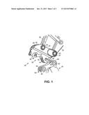
[0007] FIG. 1 is a perspective illustration of a quick coupler for coupling an attachment with a construction machine.
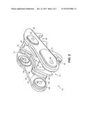
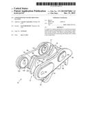
[0008] FIG. 2 is a perspective view of a coupler frame comprising unitary mounting flanges.
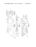
[0009] FIG. 3 is an elevation view of the outer surfaces of an exemplary unitary mounting flange.
[0010] FIG. 4 is an elevation view of an end of the exemplary unitary mounting flange of FIG. 3.
[0011] FIG. 5 is a bottom plan view of the exemplary unitary mounting flange of FIG. 3.
[0012] FIG. 6 is an elevation view of the inner surfaces of the exemplary unitary mounting flange of FIG. 3.
DETAILED DESCRIPTION OF PREFERRED EMBODIMENTS
[0013] Referring in detail to the drawings where similar parts are identified by like reference numerals, and, more particularly to FIG. 1, a coupler 20 for a construction machine, such as a back hoe or an excavator, enables rapid coupling and uncoupling of the stick 22 of the machine and attachments 24, such as buckets, jack hammers and compactors. A coupler 20 comprises, generally, a coupler body 26 affixed to a pair of laterally spaced mounting flanges 28, 30 which include portions extending above the coupler body and defining mounting pin apertures. The inner surfaces of the spaced projecting portions of the mounting flanges 28, 30 are arranged to interface with respective sides of the stick and the control link. The coupler is secured to the machine by a stick mounting pin 32 and a control link mounting pin 34 which are secured in apertures in the stick 26 and control link 36 and respective pairs of apertures defined by the projecting portions of the spaced mounting flanges.
[0014] Referring also to FIG. 2, the frame 70 of a coupler comprises, generally, a body frame 72 and a pair of flanges including portions projecting upward from the body frame. The body frame 72 of the coupler comprises, generally, a pair of elongate side plates 74, 76 which are spaced apart by a front plate 78 affixed transverse to the side plates proximate the first (front) ends of the side plates and a rear plate 80 affixed transverse to the side plates proximate the second (rear) ends of the side plates. A slot-like hook portion 82 is defined by the side plates proximate their first ends and extends generally longitudinally in the side plates. The side plates 74, 76 also define a slot-like mounting portion 84 proximate the second ends of the side plates which extends into the side plates in a direction substantially normal to the longitudinal axis of the hook portion.
[0015] To secure the coupler 20 to the stick 22 of the construction machine, the operator moves the stick to locate it between the inner surfaces of the projecting portions of the flanges 28, 30 and align an aperture in the stick with apertures defined by the flanges. The stick mounting pin 32 is inserted in the cooperating apertures in the stick and the flanges and secured, for example, by a collar 33 affixed to each end of the stick mounting pin. The operator then rotates the control link 36 by activating a hydraulic attachment or bucket cylinder (not shown) attached to the control link to align an aperture in the control link with a second pair of holes defined in the flanges. The coupler is pivotally secured to the machine's stick by the stick mounting pin and a control link mounting pin 34 which may be in secured cooperating apertures in the control link and the flanges of the coupler by collars 33.
[0016] To secure an attachment 24, such as a bucket, to the machine the operator of the maneuvers the stick 22 to locate the side plates 76, 78 of the coupler body 26 between spaced mounting plates 38, 40 on the attachment and retracts the hydraulic attachment cylinder attached to the control link 36 to rotate the coupler about the stick mounting pin 32 enabling a front pin 42 affixed to the attachment to enter the hook portion 82 of the coupler body 26. A spring biased locking knuckle 44, depressed by entry of the front pin into the hook portion, extends to lock the front pin into the hook portion. The operator then extends the attachment cylinder rotating the coupler 20 about the front pin 42 causing a rear pin 46 of the attachment to enter the mounting portion 84 in the coupler body. Extension of a hydraulic locking cylinder (not shown) located within the coupler body extends a locking wedge 48 into the mounting portion 84 securing the attachment to the stick 22 of the construction machine by locking the rear pin 46 in the mounting portion and the front pin in the hook portion. Hydraulically withdrawing the locking wedge 48 and the locking knuckle 44 enables separation of the coupler and the attachment.
[0017] The distance between the outer surfaces of the coupler body's side plates 74, 76 is dictated by the separation of the inner surfaces of the attachment's mounting plates 38, 40, which may be defined by bosses 50 and the distance between the innermost surfaces of the projecting portions of coupler's flanges 28, 30 is dictated by the outer width of the machine's stick 22 and control link 36. A spacer is typically inserted between each coupler side plate and flange plate to offset the surfaces to provide close fitting but freely movable interfaces between the coupler and the machine's stick and between the coupler and the attachment. However, heating and cooling accompanying welding on the flange plate's inner surface at the base of the projecting portion commonly distorts the projecting portions of the flange plates. It is often necessary to machine and/or add spacers to the inside surfaces of the projecting portions of the flange plates after the welded coupler has cooled for several hours to obtain the correct separation and orientation of the surfaces of the flange plates that interface with the machine's stick. The inventor reasoned that a unitary mounting flange incorporating the offset interfaces to both the coupler frame and the machine in a unitary element would eliminate the need for a spacer between the coupler body and the flange reducing the part count, enabling thickening and stiffening of the portion of the mounting flange welded to the coupler body and separate the flange to coupler body welding from the projecting portions of the flange minimizing welding induced distortion of the flange and the need to machine and/or shim the inner surfaces of the flange to obtain the proper fit up to the machine's stick and control link. In addition, the inventor reasoned that casting or forging the unitary flange would enable optimizing the placement of material making up the flange reducing the weight of the coupler.
[0018] Referring also to FIGS. 3-6, a coupler frame 70 includes a coupler body frame 72 having spaced elongate side plates 74, 76 to which are affixed respective unitary mounting flanges 86, 88. An exemplary cast or forged unitary mounting flange 88 (unitary mounting flange 86 is preferably a mirror image of mounting flange 88) comprises, generally, a machine interface portion 90, a coupler interface portion 92 and a web portion 94 uniting the coupler interface portion and the machine interface portion. The web portion 94 of the unitary mounting flange comprises generally a web 96 defined by a first (inner) surface 98 and a spaced, opposing second (outer) surface 100. One or more bosses 134, 136 providing bearing surfaces for collars 33 which are commonly used to secure the stick mounting pin 32 and the control link mounting pin 34 may project from the second surface 100 of the web. Preferably, the unitary mounting flange is cast or forged.
[0019] The coupler interface portion 92 which may include portions located proximate a first edge 102 of the web portion 94 projects outward from the first surface 98 of the web 96 to a substantially planar coupler interface surface 104 which is arranged for abutment with a respective side plate 76 of the coupler body's frame 72. The coupler interface surface 104 is preferably defined, in part, by the perimeter edge 106 of the coupler interface portion 92 which may include portions extending along the first edge 102 and preferably includes portions distal of the first edge and arranged to be substantially coextensive with the upper surface of the coupler side plate, for example the upper surface 77 of the coupler side plate 76, when the coupler interface surface is in abutment with the side plate. The coupler interface surface is also preferably defined by inner edges 108 and 110 spaced apart from and extending substantially parallel to portions of the perimeter edge. The inner edge 108 preferably defines a first relief surface 112 and the inner edge 110 preferably defines a second relief surface 114. The relief surfaces 112 and 114 are preferably spaced from the second surface 100 of the web 96 a lesser distance than the coupler interface surface 104 substantially reducing the weight of the unitary mounting flange and thereby the weight of the coupler.
[0020] The web 96 unifies the coupler interface portion 92 and the machine interface portion 90 of the unitary mounting flange 88. The machine interface portion 92 may comprise plural spaced machine interface portions 120, 122 projecting outward from the first surface 98 of the web 96.
[0021] Raw surfaces of the coupler interface portion 92 and the machine interface portion 94 most remote of the first surface 98 of the web portion 94 are preferably machined to provide a planar coupler interface surface 104 offset 132 from parallel machine interface surface(s) 124, 126. The machine interface surfaces 124, 126 may coplanar or may be offset from each other if required to match the respective widths of the stick and control link of a particular machine.
[0022] Plural apertures 128, 130 arranged to cooperate with respective apertures in the control link and the stick and receive the stick mounting pin and the control link mounting pin are defined by portions of the machine interface portion 90 and the web portion 94 of the unitary mounting flanges 86, 88.
[0023] The unitary mounting flanges 86, 88 are preferably attached to the coupler body by abutting the coupler interface surface 104 with the respective side plate, for example side plate 72, 76 of the coupler body's frame 72 and welding along portions of the perimeter edge 106 where the coupler interface surface and the side plate abut. The offset coupler interface surface 104 and machine interface surface(s) 124, 126 of the unitary mounting flange eliminates the need for a spacer between the coupler body side plates and the mounting flange reducing the part count and eliminating welding on the surface of the projecting portion of the flange. In addition, the portion of the unitary mounting flange welded to the coupler body is thicker and stiffer than the prior mounting plate which combined with distancing the mounting flange-to-coupler body welding from the projecting portion of the mounting flange reduces distortion of the portion of the flange interfacing with the machine eliminating the need to machine and/or shim the inner surface of the projecting portion of the flange.
[0024] The unitary mounting flange reduces the inventory required to produce couplers for machines with a range of stick and control link widths and arrangements, eliminates machining and shimming of the flanges after welding and reduces the weight of the coupler.
[0025] The detailed description, above, sets forth numerous specific details to provide a thorough understanding of the present invention. However, those skilled in the art will appreciate that the present invention may be practiced without these specific details. In other instances, well known methods, procedures, components, and circuitry have not been described in detail to avoid obscuring the present invention.
[0026] All the references cited herein are incorporated by reference.
[0027] The terms and expressions that have been employed in the foregoing specification are used as terms of description and not of limitation, and there is no intention, in the use of such terms and expressions, of excluding equivalents of the features shown and described or portions thereof, it being recognized that the scope of the invention is defined and limited only by the claims that follow.
User Contributions:
Comment about this patent or add new information about this topic:
Images included with this patent application:
 |  |
 |  |
| Similar patent applications: | |
| Date | Title |
|---|---|
| 2015-12-17 | Fastening system for mounting solar modules |
| 2015-11-12 | Spline press fit orientation lead in |
| 2015-11-19 | Catch portion, apparatus and manufacturing method of catch portion |
| 2015-12-10 | Cylinder unit having an adhesive bond |
| 2015-12-24 | Universal joint jaw, assembly for a double universal ball joint and machining method |
| New patent applications in this class: | |
| Date | Title |
|---|---|
| 2018-01-25 | Shaft hub connection in particular for a connecting rod |
| 2017-08-17 | Rotary machine unit |
| 2016-06-02 | Assembled body using fittings |
| 2016-05-26 | Electrical machine comprising a fastening flange |
| 2016-05-19 | Compressible vertical connector |
| Top Inventors for class "Joints and connections" | |
| Rank | Inventor's name |
|---|---|
| 1 | Steven E. Morris |
| 2 | Jennifer P. Lawall |
| 3 | Yu-Tao Chen |
| 4 | Chun-Che Yen |
| 5 | Te-Sheng Jan |