Patent application title: SYSTEMS AND METHODS FOR THE CONTROL OF WELDING PARAMETERS
Inventors:
Richard Martin Hutchison (Iola, WI, US)
Richard Martin Hutchison (Iola, WI, US)
IPC8 Class: AB23K9095FI
USPC Class:
21913001
Class name: Metal heating (e.g., resistance heating) by arc including circuits for monitoring arc parameters
Publication date: 2015-12-31
Patent application number: 20150375326
Abstract:
A welding system includes a welding torch, a power supply, one or more
sensors, and a controller is provided. The welding torch advances an
electrode toward a workpiece in a first direction. The power supply
provides a flow of electricity to the electrode for generating a welding
arc between the electrode and the workpiece. Generating the welding arc
generates a weld puddle behind the welding arc as the electrode moves in
the first direction. The sensor generates a voltage output signal based
on the amount of light received from the weld puddle. The controller is
communicatively coupled with the sensor to receive the voltage output
signal, and the sensor controls a welding parameter of the welding system
based the voltage output signal.Claims:
1. A welding system, comprising: a welding torch configured to advance an
electrode toward a workpiece; a power supply configured to provide a flow
of electricity to the electrode for generating a welding arc between the
electrode and the workpiece, wherein generating the welding arc generates
a weld puddle behind the welding arc as the electrode, the welding arc,
and/or the weld puddle produces radiation; a sensor disposed adjacent to
the welding torch and configured to detect radiation from the welding arc
reflected by the weld puddle and to generate output signals based on an
amount of radiation detected; and a controller communicatively configured
to receive the output signals or signals based upon the output signals
and to control a welding parameter of the welding system based upon
received signals.
2. The welding system of claim 1, wherein the controller is configured to control the welding parameter to maintain a penetration depth of the weld relative to a surface of the workpiece.
3. The welding system of claim 1, wherein the controller is configured to control the welding parameter to maintain a height of the weld puddle relative to a surface of the workpiece.
4. The welding system of claim 1, wherein the output signal is inversely related to a penetration depth of the weld or a height of the weld puddle relative to a surface of the workpiece.
5. The welding system of claim 1, wherein the controller is configured to detect an inception of a burn through event based upon the output signals or the signals based upon the output signals.
6. The welding system of claim 1, wherein the welding parameter comprises a current, a voltage of the flow of electricity provided to the electrode, a wire feed speed, a travel speed of the electrode, or a combination thereof.
7. The welding system of claim 1, wherein the controller is configured to control a welding parameter of a wire feeder, a power supply, a gas supply, a robotic device, the welding torch, or a combination thereof.
8. The welding system of claim 1, wherein the sensor comprises a photovoltaic cell, a photodiode, a photo-resistive element, or a combination thereof.
9. The welding system of claim 1, wherein the sensor comprises one or more apertures configured to receive radiation from the weld puddle.
10. A method, comprising: detecting, via a light sensor system, a characteristic of light emitted or reflected from a weld puddle, wherein the weld puddle is formed behind a welding arc that is produced between a welding torch and a workpiece of a welding system; determining, via an opto-electric component of the light sensor system, an output signal, wherein the output signal is representative of the characteristic of light emitted by and/or reflected from the weld puddle; and transmitting, via the light sensor system, the output signal to a controller of a welding system, wherein the controller of the welding system is configured to control a welding parameter of the welding system based on the output signal.
11. The method of claim 10, wherein the output signal is inversely related to a penetration depth of the weld or to a height of the weld puddle.
13. The method of claim 10, wherein detecting the characteristic of light comprises detecting intensity of light through an aperture of the light sensor system, wherein the aperture is configured to limit a detection area of the light sensor system.
14. The method of claim 10, wherein detecting the characteristic of light comprises detecting intensity of light at an angle relative to a central axis of the welding torch.
15. The method of claim 10, wherein the welding parameter comprises a current, a voltage of the flow of electricity provided to the electrode, a wire feed speed, a travel speed of the welding torch, or a combination thereof.
16. A welding system, comprising: control circuitry configured to: receive a signal indicative of light emitted and/or reflected by a weld puddle, wherein the weld puddle is formed behind a welding arc that is produced between a welding torch and a workpiece of a welding system; process the signal indicative of the light to monitor an operating parameter of the welding system; and determine a control signal based on the operating parameter, wherein the control signal is configured to adjust or update a welding parameter of the welding system.
17. The welding system of claim 16, wherein the operating parameter is a penetration depth of the weld relative to a surface of the workpiece, or a height of the weld puddle relative to the surface of the workpiece.
18. The welding system of claim 16, wherein the welding parameter comprises a current, a voltage of the flow of electricity provided to the electrode, a wire feed speed, a travel speed of the welding torch, or a combination thereof.
19. The welding system of claim 1, wherein the control circuitry is configured to control the welding parameter to maintain a penetration depth of the weld relative to a surface of the workpiece.
20. The welding system of claim 1, wherein the controller is configured to control a welding parameter of a wire feeder, a power supply, a gas supply, a robotic device, the welding torch, or a combination thereof.
Description:
BACKGROUND
[0001] The invention relates generally to welding systems, and more particularly, to systems and methods for controlling welding parameters of the welding system.
[0002] A wide range of welding systems and welding control regimes have been implemented for various purposes. In continuous welding operations, gas metal arc welding (GMAW) techniques allow for formation of a continuous weld bead by feeding filler material shielded by inert or active gas from a welding torch. Electrical power is applied to the welding wire and a circuit is completed through the workpiece to sustain an arc that melts the wire and the workpiece to form the desired weld. Certain related processes do not use shielding gas, and may rely upon constituents in the welding wire for forming and protecting the progressing weld.
[0003] In general, welding operations may be manual (e.g., the welding torch may be held and controlled by a human operator), and/or automated (e.g., the welding torch is manipulated by a robotic device). In either application, various welding parameters (e.g., voltage and current levels, wire feed speeds, travel speeds, etc.) are controlled to ensure an efficient and cost effective welding process. For example, in GMAW and related welding processes, various welding parameters are controlled to maintain a constant arc length. A constant arc length can provide a relatively consistent weld bead profile and weld penetration depth, thereby enhancing certain structural and aesthetic qualities of the weld. As a further example, the travel speed (e.g., rate of advancement of the torch to create the weld) may be regulated by the welding operator in manual operations, or it may be pre-set in advance for automated applications.
[0004] However, unpredictable variables in the welding environment make it difficult to accurately determine and control welding parameters. Accordingly, it may be beneficial to provide for systems and methods for controlling the various welding parameters based on a simple sensor feedback system.
BRIEF DESCRIPTION
[0005] In one embodiment, a welding system including a welding torch, a power supply, one or more sensors, and a controller is provided. The welding torch advances an electrode toward a workpiece in a first direction. The power supply provides a flow of electricity to the electrode for generating a welding arc between the electrode and the workpiece. Generating the welding arc generates a weld puddle behind the welding arc as the electrode moves in the first direction. The sensor generates a voltage output signal based on the amount of light received from the weld puddle. The controller is communicatively coupled with the sensor to receive the voltage output signal, and the sensor controls a welding parameter of the welding system based the voltage output signal.
[0006] In another embodiment, a method is provided. The method includes detecting, via a light sensor, an intensity of light emitted/reflected from a weld puddle. The weld puddle is formed behind a welding arc that is produced between a welding torch and a workpiece of a welding system. The method also includes determining, via an opto-electric component disposed within the light sensor, a voltage output signal. The voltage output signal is related (e.g., inversely related) to a light intensity of the weld puddle. The method also includes transmitting, via the light sensor, the voltage output signal to a controller of a welding system. The controller of the welding system is configured to control a welding parameter of the welding system based on the voltage output signal.
[0007] In another embodiment, a welding system with control circuitry is provided. The control circuitry receives a signal indicative of a light intensity of a weld puddle. The weld puddle is formed behind a welding arc that is produced between a welding torch and a workpiece of a welding system. The control circuitry processes the signal indicative of the light intensity to monitor an operating parameter of the welding system and determines a control signal based on the operating parameter. The control signal is configured to adjust or update a welding parameter of the welding system.
DRAWINGS
[0008] These and other features, aspects, and advantages of the present invention will become better understood when the following detailed description is read with reference to the accompanying drawings in which like characters represent like parts throughout the drawings, wherein:
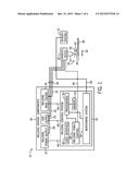
[0009] FIG. 1 is a block diagram of an embodiment of a welding system that may employ a sensor system for monitoring welding parameters, in accordance with an embodiment;
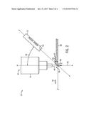
[0010] FIG. 2 is a perspective view of an embodiment of the sensor system of FIG. 1 used to detect a light intensity during the welding process, in accordance with an embodiment;
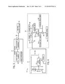
[0011] FIG. 3 is a block diagram of an embodiment of the sensor system of FIG. 1 communicatively coupled to a control system of the welding system of FIG. 1, in accordance with an embodiment;
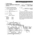
[0012] FIG. 4 is a block diagram of an embodiment of feedback loop utilized by the welding system of FIG. 1 to control various welding parameters, in accordance with an embodiment; and
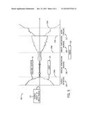
[0013] FIG. 5 is a plot of an embodiment illustrating the relationship between a voltage output of the sensor system of FIG. 1 and welding parameters of the welding process.
DETAILED DESCRIPTION
[0014] Embodiments of the present disclosure are directed toward systems and methods for controlling welding system parameters based on a light intensity of a weld pool (e.g., weld puddle) behind the welding arc produced by the welding system. In particular, a simple sensor system is positioned in proximity to the weld pool and is disposed in a manner that allows light to easily impinge upon it as the penetration depth of the weld is increased. In response to the light received, the sensor system produces an electrical output that is related to a welding parameter (e.g., penetration depth of the weld, height of a welding bead, etc.) achieved during the welding process. For example, the electrical output may be proportionally related, inversely related, directly related, etc. Specifically, the sensor system includes an opto-electrical component (e.g., photo-resistor, photo-voltaic, or photo-diode) with electrical characteristics that change in relationship to a magnitude of the light received from a sensing area (e.g., area behind the welding arc). In certain embodiments, the sensor system includes one or more apertures that focus the sensing area of the sensor system to the region of the weld pool (e.g., weld puddle) that is behind the welding arc. In this manner, the sensor system provides sensor feedback information of the welding process via a simple analog electric circuit and/or digital algorithm that can be implemented on an inexpensive microprocessor.
[0015] In certain embodiments, a monitoring system disposed within a welding control system of the welding system receives the electrical output (e.g., feedback signals) from the sensor system, and processes the received signals. Based on the sensor feedback, the welding control system can make adjustments to welding components and/or operating parameters to correct for deviations and/or errors in the welding process. For example, if the penetration depth of the weld is too great during the welding process, the welding control system can utilize the sensor feedback to compensate for the deviation and increase the travel speed of the welding torch. Conversely, if the penetration depth of the weld is too shallow, the welding control system can utilize the sensor feedback to compensate for the deviation and decrease the travel speed of the welding torch.
[0016] FIG. 1 is a block diagram of an embodiment of a welding system 10 that utilizes a sensor system 12 for monitoring welding parameters, in accordance with an embodiment. The illustrated embodiment depicts an automated welding system 10, with an automatic welding torch 14 that is manipulated by a robotic device 16. However, it should be noted that aspects of the embodiments described herein may be applicable to a manual welding system, such as any manual welding system where the welding torch 14 is held and controlled by a human operator.
[0017] The welding system 10 includes various components (e.g., welder 18) that provide supplies, such as welding wire, power, and so forth, to a welding operation 20 being performed by the robot 16. In the illustrated embodiment, the welder 18 includes a welding power supply 22, a gas supply 24, and a wire feeder 26 that supply power through a cable 28, gas through a cable 30, and wire through cable 32, respectively, to the welding torch 14 for use in the welding operation 20. It should be noted that in some embodiments, the cables 28, 30, and 32 may be combined into a single cable 34 that couples the welder 18 to the welding torch 14. In addition, the welder 12 also includes a welding control system 35 that is configured to control various aspects of the automatic welding system 10. For example, the amount of power, gas, and wire provided to the welding torch 14 may be regulated by the control system 35 based on the welding process, and/or based on various sensor feedback received from the sensor system 12.
[0018] The welding system 10 utilizes the various components 18 to produce a welding arc 36 on a workpiece 38. The welding arc 36 may be of any type of weld, and may be oriented in any desired manner, including MIG, metal active gas (MAG), various waveforms, tandem setup, and so forth. In particular, the power supply 22 provides a flow of electricity to the welding wire 40 (supplied by the wire feeder 26), which acts as an electrode. The welding wire 40 is fed through the welding torch 14 to form the welding arc 36, melted by the welding arc 36, and deposited on the workpiece 38. In addition, the workpiece 38 is coupled to the power supply 22 by a clamp connected to a work cable (not illustrated) to complete an electrical circuit when the welding arc 36 is established between the welding wire 40 and the workpiece 38. Placement of the welding torch 14 at a location proximate to the workpiece 38 allows electrical current, which is provided by the power supply 22 and routed to the welding torch 14, to arc from the welding wire 40 to the workpiece 38. As described above, this arcing completes an electrical circuit that includes the power supply 22, the welding torch 14, the workpiece 38, and the work cable. Particularly, in operation, electrical current passes from the power supply 22, to the welding torch 14, and to the workpiece 38, which is typically connected back to the power supply 22. The arcing generates a relatively large amount of heat that causes part of the workpiece 38 and the filler metal of the welding wire 40 to transition to a molten state. In particular, a weld puddle 42 in the molten state is formed behind the welding torch 14 as the torch 14 moves in a forward direction 44.
[0019] To shield the weld area from being oxidized or contaminated during welding, to enhance arc performance, and to improve the resulting weld, the welding system 10 also may feed an inert shielding gas to the welding torch 14 from the gas source 24. It is worth noting, however, that a variety of shielding materials for protecting the weld location may be employed in addition to, or in place of, the inert shielding gas, including active gases and particulate solids.
[0020] As noted above, the control system 35 control one or more welding parameters of the welding system 10. For example, the control system 35 is configured to regulate the amount of power, gas, or wire provided to the welding torch 14 via the cables 28, 30, or 32, respectively. Indeed, one or more control signals 46 between the control system 35 and other components of the welder 18 (e.g., the welding power supply 22, the gas supply 24, welding wire feeder 26, etc.) are used to regulate and control the timing and quantity of these supplies. For example, the control system 35 may control the welding power output that is applied to the welding wire 40 for carrying out the desired welding operation.
[0021] In certain embodiments, the control system 35 controls the one or more welding parameters in response to sensor feedback received from the sensor system 12. The sensor system 12 may provide signals relating to an operating parameter of the welding system, such as current, voltage, or light intensity of the welding arc 12. For example, the sensor system 12 includes one or more sensors located throughout the welding system 10, such as, for example, sensors disposed proximate to the welding torch such that the sensors react a magnitude of light of the weld puddle 42. Based on these detected parameters within the welding process, the control system 35 may output control signals to various components of the welding system 12 to adjust one or more welding parameters. For example, based on the sensor feedback, a welding torch control 48 disposed within the control system 35 may regulate the robotic device 16 coupled to the welding torch 14 to increase or decrease a travel speed of the torch 14. Other welding parameters may include the current provided to the welding wire 24, the voltage of the flow of electricity provided to the welding wire 24, welding wire feed speed, and so forth.
[0022] The control system 35 also includes one or more processors 50 (e.g., processing circuitry 50) and memory 52 (e.g., memory circuitry 52), and may be communicatively coupled to the welding torch control 48 and the monitoring system 54. The monitoring system 54 receives one or more feedback signals from the sensor system 12. The sensor system 12 may be a single sensor or an array of sensors used to detect the light emitted from the welding arc 36, such as for example, the light emitted/reflected/by the weld puddle 42. Based on the feedback signals received, the processing circuitry 50 may execute instructions stored in the memory circuitry 52 to generate one or more control signals to provide to the welding torch control 48, the welding power supply 22, the gas supply 24, the welding wire feeder 26, and so forth. Specifically, based on the control signals, the control system 35 may continuously adjust parameters of the welding system 10, such as the power supplied to the welding wire 40 or the speed of the welding torch 48, in order to maintain certain welding parameters. As an example, it may be desirable to maintain a certain penetration depth of the weld or a certain height of the weld puddle 42, and these parameters may be maintained approximately constant or consistent based on the sensor feedback from the sensor system 12. The various sensors may generate signals indicative of the different detected properties at a predetermined interval, and the processing circuitry may receive and process the sensor signals to output control signals nearly instantaneously. This may allow for relatively instantaneous control of the welding process.
[0023] Further, the control system 35 includes a user interface 56 that may allow for selection of settings such as the type of weld process, the type of wire to be used, welding parameter settings, and so forth. In particular, the user interface 56 may be utilized by a welding operator to input various thresholds, beginning values, ideal values, for the one or more welding parameters regulated by the welding system 10. For example, the user may input a certain threshold height of the weld puddle 42, and the processing circuitry 50 may utilize the sensor feedback to regulate the height of the weld puddle 42 based on the threshold.
[0024] FIG. 2 is a perspective view of an embodiment of the sensor system 12 of FIG. 1, where the sensor system 12 is used to detect a light intensity of the weld puddle 42 during the welding process, in accordance with an embodiment. In particular, in some embodiments, the sensor system 12 is positioned in proximity to the welding torch 14, in a manner that allows the light emitted/reflected from the weld puddle 42 to be captured by sensor system 12. For example, the sensor 12 can be positioned such that it is able to monitor the molten weld puddle 42 behind the welding arc 36 that is formed during the welding process. Indeed, the sensor 12 may be disposed anywhere within the welding system 10 (e.g., behind, next to, around, or near the arc 36, the torch 14, the robotic arm 16, or the welding operator, etc.), so long as it receives an amount of light from the weld puddle 42 of the welding process.
[0025] Light from the welding arc 36 (e.g., the weld puddle 42) may be intercepted by the sensor system 12, which converts the detected light intensity to an electronic signal that is sent to the control system 35 for processing. In the illustrated embodiment, the sensor system 12 communicates the feedback signal to the control system 35 via a wire 58 (as illustrated in FIG. 1). In other embodiments, however, the sensor system 35 may communicate the signal wirelessly. The sensor system 12 may include any device capable of outputting an electrical signal in response to incident light. For example, the sensor system 12 may include one or more optical sensors and one or more opto-electrical components, such as photovoltaic cells, photodiodes, photo-resistive elements, or a combination thereof. In some embodiments, the sensor system 12 may be configured to output an electrical signal that is linearly proportional to the detected light. In other embodiments, non-linearity within the light sensor 48 may be mapped to a corresponding linearizing function via the control system 35.
[0026] In some embodiments, the sensor system 12 may be disposed around the welding torch 14 in a specific position and/or orientation that allows it to detect the magnitude of the light from the weld puddle 42. For example, the sensor system 12 may be disposed at an angle 60 relative to an axis 62 (e.g., a central axis 62 of the welding torch 14) approximately perpendicular to the workpiece 38. In particular, the angle 60 may be between approximately 15° and 30°, between approximately 10° and 40°, or between approximately 5° and 50°. Further, the angle 60 of the sensor system 12 may be away from the axis 62 in a direction opposite to the direction of travel 44 (e.g., forward direction 44) of the torch 14. The angle 60 of the sensor system 12 may be adjusted to ensure that a maximum amount of light emitted/reflected from the weld puddle 42 is gathered by the sensor system 12.
[0027] In certain embodiments, the angle 60 of the sensor system 12 may be adjusted such that the light emitted/reflected from the weld puddle 42 is not obscured and/or overpowered by other light emitted during the welding process, such as light directly from the welding arc 36. The sensor system 12 includes one or more apertures 64 (e.g., pin holes 64, operable windows, etc.) that focus the sensing area of the sensor system 12 to the region of the weld puddle 42 (e.g., weld pool) that is behind the welding arc 36. In particular, the light incident upon the aperture 64 is related to the penetration depth of the weld 65 (or, conversely, to a height 66 of the weld puddle 42). The penetration depth of the weld 65 and the height 66 of the weld puddle 42 may be relative to the surface of the workpiece 38. The geometry of the aperture 64 is configured so that as the depth of penetration of the weld 65 is increased, the amount of light received by the sensor system 12 increases. Indeed, as the penetration depth of the weld 65 increases, the weld puddle 42 tends to be less convex, and this allows more of the light from the weld puddle 42 to be reflected to the sensor 12. In some situations, increased penetration depth 65 of the weld causes the arc column 36 to move down, allowing some of the light from the arc 36 to come into direct view of the sensor system 12.
[0028] FIG. 3 is a block diagram of an embodiment of the sensor system 12 of FIG. 1 communicatively coupled to the control system 35, in accordance with an embodiment. As noted above, the sensor system 12 includes one or more light apertures 64, a light sensitive element 68 (e.g., optical sensor 68), and one or more opto-electrical components 70 (e.g., photo-resistor, photo-voltaic, or photo-diode). The resistance of the opto-electrical component 70 changes in response to the magnitude of light incident on the light sensitive element 68. Typically, the resistance value of the component 70 is reduced in proportion to the amount of light that impinges upon it, and may include circuitry configured to convert incident light detected by it into an electrical signal.
[0029] Accordingly, the sensor system 12 provides a voltage output to the monitoring system 54 of the control system 35 based upon the amount of light picked up from the weld puddle 42. The sensor system 12 may be configured with wired communications (e.g., wire 58) and/or wireless communications with the control system 35. Further, as noted above with respect to FIG. 1, the control system 35 controls the one or more welding parameters in response to sensor feedback received from the sensor system 12. In some embodiments, the control system 35 may evaluate the sensor feedback, and may determine which control signals and which welding parameters should be altered, if any, to maintain a consistent and efficient welding process. For example, to maintain a desired arc length, the wire feed speed of the wire feeder 26 may be adjusted.
[0030] FIG. 4 is a block diagram of an embodiment of feedback loop 72 utilized by the welding system of FIG. 1 to control various welding parameters. In particular, once the welding system 10 has been activated and a welding operation has begun, the feedback loop 72 may be utilized by the welding control system 35 to obtain sensor feedback from the sensor system 12, adjust one or more welding parameters based on the sensor feedback via one or more control signals, and obtain updated sensor feedback from the sensor system 12 based on the updated welding operation. The feedback loop 72 may include various sensor feedback information (e.g., a signal related to the magnitude of the light emitted/reflected from the weld puddle 42) and various operating parameters (e.g., a voltage level, a weld current level, a travel speed, a wire feed speed, a power supply, a gas supply, etc.), or any combination thereof. In particular, the feedback loop 72 may be utilized to detect whether sensor feedback indicates deviations from a consistent welding process and/or welding defects. In certain embodiments, this typically involves a comparison of the feedback data, or data derived from the feedback data, to known "good weld" characteristics, known defect signatures, pre-set thresholds, limits, or values, or a combination thereof.
[0031] The feedback loop 72 includes first obtaining sensor feedback information from various components of the sensor system 12. For example, the illustrated embodiment depicts a photo-resistor 74 as the opto-electrical component 70 of the sensor system 12. Further, the illustrated embodiment includes a fixed resistor 76 the voltage across which changes based on a magnitude of light (e.g., radiation) incident upon the light sensitive element 68. As noted above, the resistance value of the opto-electrical component 70 is reduced in proportion to the amount of light that impinges on the light sensitive element via the apertures 64. Accordingly, in this example, the photo-resistor 74 and the fixed resistor 76 establish a voltage divider circuit such that the voltage across the photo-resistor 74 is reduced in direct proportion to the light incident upon it. This configuration may be beneficial for representing a relationship between a sensor voltage output 78 and the height 66 of the weld puddle 42. For example, as the penetration depth 65 and/or the height of the weld puddle 66 increases, a greater amount of light is incident upon the sensor system 12, there is a greater drop in sensor voltage. It should be noted that other configurations of the photo-resistor 74 may be beneficial for clearly showing other welding parameter relationships, and such configurations may be easily implemented within the embodiments described herein.
[0032] As noted above, the sensor voltage output 78 may be transmitted to the control system 35. The processor 50 may utilize the sensor feedback information received to determine adjustments to one or more welding parameters of the welding system 10. In the illustrated embodiment, the feedback loop 72 is configured for the adjustment of the travel speed of the welding torch 14. For example, the processor 50 may take the negative of the actual light 80 (e.g., Vlight 80) via an inverter 82 to obtain -Vlight 84. Further, the negative of the actual light (-Vlight 84) is summed, via a Σ function 86, with a light sensor voltage representative of a desired penetration level 88 (e.g., Vlight set 88). The desired penetration level 88, or any desired thresholds, limits, or level of other welding parameters, may be pre-set and stored within the memory 52 by a welding operator via the user interface 56. The sum of the negative of the actual light (-Vlight 84) with a light sensor voltage representative of a desired penetration level (e.g., Vlight set 88) produces an error term (ERRORlight 90). This error term is then multiplied by a gain factor 92 and the result (e.g., α(Vlight set-Vlight) 94) is summed, via the Σ function 86, with a voltage representing the nominal motor speed set point (e.g., Vmotor speed nom 96).
[0033] In some embodiments, if the sensor feedback 80 is lower than the set point 88 (indicating that the depth of the penetration 65 is too high), the error term 90 will be positive and a determined motor speed 98 (e.g., Vmotor speed 98) of the welding torch 14 will be increased from the nominal motor speed 98 to compensate for the increased depth of penetration 65. Likewise, if the sensor feedback 80 is greater than the set point 88 (indicating that the depth of the penetration 65 of the weld is too low), the error term 90 will be negative and the determined motor speed 98 (e.g., Vmotor speed 98) will be reduced from the nominal set point 98. In this manner, the travel speed of the welding torch 14 may be regulated by the control system 35 via one or more control signals to maintain a relatively constant penetration depth throughout the weld. Further, is should be noted that parameters other than travel speed (e.g., wire feed speed, arc power, etc.) could be employed to maintain constant penetration depth of the weld based upon the sensor feedback.
[0034] In particular, is should be noted that the embodiments described herein can be processed with a simple analog electrical circuit or digital algorithm that can be implemented on an inexpensive microprocessor. Indeed, in some embodiments, certain benefits of the present embodiments include the simplicity of the processing techniques utilized to determine parameters of the welding process (e.g., depth of penetration, height of weld puddle, etc.). In some situations, more complex optical sensing systems are utilized (e.g., cameras), which may require specialized vision analysis software to process the optical feedback received.
[0035] FIG. 5 is a plot 100 of an embodiment illustrating the relationship between the voltage output 78 of the sensor system 12, a magnitude of light 101 and/or radiation 101 incident upon the sensor system 12, the penetration depth 65 of the weld and/or the height 66 of the weld puddle 42. The timescale 102 of the plot 100 is divided into different time periods (e.g., a weld puddle initiation 104, a gradual penetration increase 106, an abrupt penetration increase 108, and a burn through 110) to illustrate this relationship between the voltage output 78, the penetration depth 65 of the weld and/or the height 66 of the weld puddle 42, and the magnitude of light incident upon the sensor system 12. As mentioned above, such as with respect to the feedback loop 72 of FIG. 4, the sensor voltage output 78 of the sensor system 12 can be correlated to the penetration depth 65 of the weld and/or the height 66 of the weld puddle 42. For example, as the penetration depth 65 and/or the height of the weld puddle 66 increases, the amount of light 101 incident upon the sensor system 12 increases, and the corresponding sensor voltage output 78 decreases.
[0036] Accordingly, in the illustrated embodiment, as a magnitude of the light 101 increases (e.g., the amount of light 101 incident upon the sensor system 12), the voltage output 78 decreases. For example, during the weld puddle initiation, the amount of light 101 incident upon the sensor system 12 gradually increases, leading to a gradual decrease in the voltage output 78. In some situations, the operator and/or the robotic device 16 may initiate a gradual increase in penetration depth, as illustrated by the time point 106a. Further, during the time period where the welding torch 14 gradually increases penetration depth (e.g., time period 106), the amount of light 101 and the voltage output 78 reflect a somewhat steady balance. Specifically, during the time period 106, the sensor system 12 may receive light reflected and/or emitted by the weld puddle 42. In particular, during this time period, the height 66 of the weld puddle 42 is generally around a desired height threshold 112. However, with the initiation of an abrupt increase in penetration depth, as indicated by the time point 108a, the sensor system 12 may begin to receive light from the weld puddle 42 and/or the welding arc 36. Accordingly, during the period of time where there is an abrupt penetration increase, (e.g., time period 108), the light 101 incident upon the sensor system 12 abruptly increases and the voltage output 78 of the sensor system 12 abruptly decreases.
[0037] In certain embodiments, the control system 35 may receive feedback signals related to the voltage output 78. Further, the control system 35 may process these signals, and take appropriate measures to correct for deviations in the welding process, such as if there are abrupt penetration depth increases, as illustrated in time period 108. For example, the control system 35 may transmit one or more signals to increase the travel speed of the welding torch 14 in order to correct for the abrupt increase in welding penetration 108. In the event that such adjustments are not taken, the welding process can lead to errors, such as a burn through incident (e.g., time period 110). These incidents may occur if excessive heat causes excess weld metal to penetrate through the location of the weld. That is, excess penetration may have occurred due to factors such as excess wire feed speed, excessively slow travel speed, and so forth. In some burn through incidents, the light disperses the welding location, leading to a sudden voltage output 78 increase.
[0038] Accordingly, it may be beneficial to detect an inception of the burn through incident, as indicated by the time point 110a, before the completion of the burn through incident, as indicated by the time point 110b. The inception of the burn through incident 110a is approximately around the time 102 where the amount of light 101 begins to disperse, such that the sensor system 12 receives less emitted and/or reflected light from the welding arc 32 and/or the weld puddle 42. Further, in some situations, the burn through incident 110 is at a completion (e.g., time point 110b) when the amount of light 101 received by the sensor is less than the amount of light received by the sensor system 12 during the puddle initiation 104.
[0039] Present embodiments of the light system 12 may be used to control welding parameters in both fully automated, semi-automatic, and manual welding systems 10. More specifically, the light system 12 may be positioned proximate to the welding torch 14 that is manipulated either robotically or manually by an operator. In some manual welding situations, the operator may respond to various audible or visual alerts or warnings provided by the control system 35 when the processing circuitry 50 determines that one or more welding parameter adjustments are needed based on the sensor feedback received. Further, the operator may take corrective measures, such as increasing or decreasing the travel speed of the welding torch 14 or any other parameter, in response to the alerts and warnings.
[0040] While only certain features of the invention have been illustrated and described herein, many modifications and changes will occur to those skilled in the art. It is, therefore, to be understood that the appended claims are intended to cover all such modifications and changes as fall within the true spirit of the invention.
User Contributions:
Comment about this patent or add new information about this topic:
| People who visited this patent also read: | |
| Patent application number | Title |
|---|---|
| 20210335007 | ACTIVE TARGETS FOR AUTOMATIC OPTICAL SENSOR ALIGNMENT |
| 20210335006 | INFORMATION PROCESSING APPARATUS, IMAGE ORIENTATION DETERMINATION METHOD, AND MEDIUM |
| 20210335005 | Enterprise System Augmented Reality Detection |
| 20210335004 | TEXTURE-BASED POSE VALIDATION |
| 20210335003 | SYSTEMS AND METHODS TO FACILITATE INTERACTION BY ONE OR MORE PARTICIPANTS WITH CONTENT PRESENTED ACROSS MULTIPLE DISTINCT PHYSICAL LOCATIONS |
Images included with this patent application:
 |  |
 |  |
 |
| Similar patent applications: | |
| Date | Title |
|---|---|
| 2016-03-31 | Systems and methods for gesture control of a welding system |
| 2016-03-24 | Systems and methods for welding zinc-coated workpieces |
| 2016-02-11 | System and method of marking a welding workpiece |
| 2016-03-10 | Systems and methods for coolant drawback |
| 2015-12-31 | System and method of monitoring welding information |
| New patent applications in this class: | |
| Date | Title |
|---|---|
| 2019-05-16 | Detection device for an active glare protection device |
| 2016-07-07 | Synchronized image capture for welding machine vision |
| 2016-01-21 | Disposition for signaling by means of a vibratory system placed in equipment for measuring and analysis of welding parameters in real time |
| 2015-12-10 | Welding device and welding method |
| 2015-03-05 | Systems, methods, and apparatuses for monitoring weld quality |
| New patent applications from these inventors: | |
| Date | Title |
|---|---|
| 2016-02-25 | Devices and methods for analyzing spatter generating events |
| 2015-12-31 | System and method for controlling wire feed speed |
| 2015-04-30 | Extraction of arc length from voltage and current feedback |
| 2015-03-19 | Synchronized rotating arc welding method and system |
| 2014-12-18 | Systems and methods for anomalous cathode event control |
| Top Inventors for class "Electric heating" | |
| Rank | Inventor's name |
|---|---|
| 1 | Steven R. Peters |
| 2 | Shou-Shan Fan |
| 3 | Chen Feng |
| 4 | Kai-Li Jiang |
| 5 | Chang-Hong Liu |