Patent application title: THIN BIN DISPLAY
Inventors:
Curtis Taylor (Chagrin Falls, OH, US)
Curtis Taylor (Chagrin Falls, OH, US)
Aaron Misener (Chagrin Falls, OH, US)
Aaron Misener (Chagrin Falls, OH, US)
IPC8 Class: AB65D2520FI
USPC Class:
206521
Class name: Special receptacle or package shock protection type (e.g., free fall)
Publication date: 2015-12-24
Patent application number: 20150367989
Abstract:
An improved storage and/or display system having one or more protection
strips or guards.Claims:
1. A system for storage and/or display, the system comprising: a first
side wall comprising a first front edge, a first outer face, and a first
inner face; a second side wall comprising a second front edge, a second
outer face, and a second inner face, the second inner face positioned to
face the first inner face; a back wall extending between the first side
wall and the second side wall; a first bin extending forward from the
back wall to be positioned between the first and second side walls,
extending from the first inner face to the second inner face, and
comprising a first top edge; and a protective component connected to at
least one other component selected from the group consisting of the first
front edge, the second front edge, first outer face, the second outer
face, the back wall, and the first top edge.
2. The system of claim 1, wherein the protective component is a protection strip or guard connected to at least one of the first front edge or the second front edge.
3. The system of claim 1, wherein the protective component is a protection strip or guard connected to the first top edge of the first bin.
4. The system of claim 3, wherein the first top edge is arcuate.
5. The system of claim 1, wherein the protective component is a protective panel connected to at least one of the first outer face or the second outer face.
6. The system of claim 1, wherein the protective component is a protective panel connected to the back wall.
7. The system of claim 1, wherein the protective component comprises rubber.
8. The system of claim 1, wherein the protective component comprises plastic.
9. The system of claim 1, wherein the protective component comprises metal.
10. The system of claim 1, wherein the first side wall has a width that is a distance from the back wall to the first front edge, the first side wall comprises a lower portion positioned at least partially beneath the first bin and an upper portion positioned at least partially above the first bin, and the lower portion is angled relative to the upper portion such that the width of the first side wall is greater at a lower edge of the lower portion relative to the width of the upper portion.
11. system of claim 10, wherein the second side wall has a width that is a distance from the back wall to the second front edge, the second side wall comprises a lower portion positioned at least partially beneath the first bin and an upper portion positioned at least partially above the first bin, and the lower portion is angled relative to the upper portion such that the width of the second side wall is greater at a lower edge of the lower portion relative to the width of the upper portion.
12. system of claim 10, wherein the protective component is connected to the upper portion and the lower portion.
13. The system of claim 1, wherein the protective component is connected by adhesive to the at least one other component.
14. The system of claim 1, wherein the protective component is connected by rivets to the at least one other component.
15. The system of claim 1, wherein the protective component is connected by screws to the at least one other component.
16. The system of claim 1, wherein the protective component is connected by bolts to the at least one other component.
17. The system of claim 1, wherein the protective component is connected by snap connection to the at least one other component.
18. The system of claim 1, wherein the protective component is connected by slot fit connection to the at least one other component.
19. A method comprising: storing an item in an apparatus comprising (i) a first side wall comprising a first front edge, a first outer face, and a first inner face; (ii) a second side wall comprising a second front edge, a second outer face, and a second inner face, the second inner face positioned to face the first inner face; (iii) a back wall extending between the first side wall and the second side wall; (iv) a first bin extending forward from the back wall to be positioned between the first and second side walls, extending from the first inner face to the second inner face, and comprising a first top edge; and (v) a protective component connected to at least one other component selected from the group consisting of the first front edge, the second front edge, first outer face, the second outer face, the back wall, and the first top edge.
20. A method comprising: displaying an item on an apparatus comprising (i) a first side wall comprising a first front edge, a first outer face, and a first inner face; (ii) a second side wall comprising a second front edge, a second outer face, and a second inner face, the second inner face positioned to face the first inner face; (iii) a back wall extending between the first side wall and the second side wall; (iv) a first bin extending forward from the back wall to be positioned between the first and second side walls, extending from the first inner face to the second inner face, and comprising a first top edge; and (v) a protective component connected to at least one other component selected from the group consisting of the first front edge, the second front edge, first outer face, the second outer face, the back wall, and the first top edge.
Description:
PRIORITY CLAIM
[0001] The present application claims priority to U.S. Provisional Patent Application No. 62/014,255, filed on Jun. 19, 2014, the entire contents of which are incorporated herein by reference.
BACKGROUND
[0002] The present invention is a container and, more particularly, a storage and/or display system.
BRIEF DESCRIPTION OF THE FIGURES
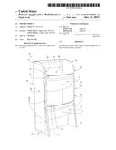
[0003] FIG. 1 shows a front perspective view of an embodiment of a storage and/or display system provided by the present disclosure.
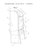
[0004] FIG. 2 shows a side perspective view of an embodiment of a storage and/or display system provided by the present disclosure.
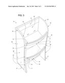
[0005] FIG. 3 shows a front perspective view of an embodiment of a storage and/or display system provided by the present disclosure.
DETAILED DESCRIPTION
[0006] Referring now to FIGS. 1-3, there is one non-limiting embodiment of the storage and/or display system 10 in accordance with the present invention, FIGS. 1-3 illustrate the storage and/or display system 10 having two storage bins 11,12; however, it can be appreciated that the storage and/or display system 10 can have more storage bins than the two storage bins 11,12. The height and width of the storage and/or display system 10 are non-limiting. The materials used to form the storage and/or display system 10 are non-limiting.
[0007] The front bases 21,31 of the storage and/or display system 10 is illustrated as being wider than the tops 22,32 of the storage and/or display system 10 so as to provide additional stability to the storage and/or display system 10; however, this is not required. The faces 13,14 of the bins 11,12 is arcuate or curved; however, this is not required. The front edges 23,33 of the storage and/or display system 10 can optionally include protection strips or guards 2434 to inhibit or prevent damage to the storage and/or display system 10; however, this is not required. The protection strips or guards 24,34 can be made of a durable material such as wood, metal, plastic, rubber, etc. The protection strips or guards 24,34 can be connected to the front edges 23,33 by various means (e.g., adhesive, rivets, screws, bolts, snap connection, slot fit connection, etc.). One or both sides 25,35 of the storage and/or display system 10 can optionally include a protective panel 26 to inhibit or prevent damage to the storage and/or display system 10; however, this is not required. The protective panel 26 can be made of a durable material such as wood, metal, plastic, rubber, etc. The protective panel 26 can be connected to the side by various means (e.g., adhesive, rivets, screws, bolts, snap connection, slot fit connection, etc.). The top edges 15,16 of the faces 13,14 of one or more of the bins 11,12 can include a protection strip or guard 17,18. The protection strip or guard 17,18 can be made of a durable material such as wood, metal, plastic, rubber, etc. The protection strip or guard 17,18 can be connected to the top edges 15,16 by various means (e.g., adhesive, rivets, screws, bolts, snap connection, slot fit connection, etc.). The back face 40 of the one or more of the bins 11,12 can include a protection panel 41. The protection panel 41 can be made of a durable material such as wood, metal, plastic, rubber, etc. The protection panel 41 can be connected to the back face 40 by various means (e.g., adhesive, rivets, screws, bolts, snap connection, slot fit connection, etc.).
[0008] It will thus be seen that the objects set forth above, among those made apparent from the preceding description, are efficiently attained, and since certain changes may be made in the constructions set forth without departing from the spirit and scope of the invention, it is intended that all matter contained in the above description and shown in the accompanying drawings shall be interpreted as illustrative and not in a limiting sense. The invention has been described with reference to preferred and alternate embodiments. Modifications and alterations will become apparent to those skilled in the art upon reading and understanding the detailed discussion of the invention provided herein. This invention is intended to include all such modifications and alterations insofar as they come within the scope of the present invention. It is also to be understood that the following claims are intended to cover all of the generic and specific features of the invention herein described and all statements of the scope of the invention, which, as a matter of language, might be said to fall therebetween. The invention has been described with reference to the preferred embodiments. These and other modifications of the preferred embodiments as well as other embodiments of the invention will be obvious from the disclosure herein, whereby the foregoing descriptive matter is to be interpreted merely as illustrative of the invention and not as a limitation. It is intended to include all such modifications and alterations insofar as they come within the scope of the appended claims.
User Contributions:
Comment about this patent or add new information about this topic:
| People who visited this patent also read: | |
| Patent application number | Title |
|---|---|
| 20160036705 | METHOD AND DEVICE FOR CONFIGURING LINK IN WIRELESS LAN SYSTEM |
| 20160036704 | Method for Adjusting Media Stream Transmission Bandwidth and Related Apparatus |
| 20160036703 | SCALABLE MAC ADDRESS VIRTUALIZATION |
| 20160036702 | FORWARDING PACKETS |
| 20160036701 | METHODS AND ARRANGEMENTS TO SIGNAL AN ACKNOWLEDGEMENT POLICY IN A SHORT FRAME |
Images included with this patent application:
 |  |
 |  |
| New patent applications in this class: | |
| Date | Title |
|---|---|
| 2018-01-25 | Shock-absorbing device and package thereof |
| 2016-09-01 | Method of packaging a product for shipment and product-shipping package |
| 2016-07-14 | Protective edge inserts, cases including such inserts and methods of making and using |
| 2016-07-07 | Hollow tube cushioning packaging material structure |
| 2016-07-07 | Bumpers for protective cases |
| New patent applications from these inventors: | |
| Date | Title |
|---|---|
| 2022-09-15 | Seam tape tool |
| 2021-12-30 | Expandable hose |
| 2019-01-03 | Security sensor |
| 2015-12-31 | Scissor lift pallet lifter |
| Top Inventors for class "Special receptacle or package" | |
| Rank | Inventor's name |
|---|---|
| 1 | Donald E. Weder |
| 2 | Brett R. Glass |
| 3 | Daniel Lee Bizzell |
| 4 | Andrea Biondi |
| 5 | Nicole E. Glass |