Patent application title: DEFROST APPLIANCE
Inventors:
John L. Stantinos (Astoria, NY, US)
IPC8 Class: AF25D2100FI
USPC Class:
62155
Class name: Preventing, removing or handling atmospheric condensate defrosting including time or program actuator
Publication date: 2015-12-17
Patent application number: 20150362247
Abstract:
A defrost appliance is provided that over comes the limitations of other
methods of defrosting by use of an insulated closed inner shell,
providing refrigeration and ultra violet light to control the
proliferation of bacteria and circulating liquid via a pump raining it
down on sealed frozen food to expedite thawing of frozen food in a
controlled environment a quick, efficient, safe, easy to use means for
defrosting frozen food.Claims:
1. A defrost appliance for thawing frozen foods comprising: an outside
shell, an inner shell disposed within the outer shell, the inner shell
providing an inner volume having an opening therein; a removable,
perforated drip pan disposed within the inner volume of the inner shell;
a water manifold disposed within the inner shell vertically higher than
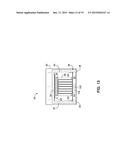
the drip pan, the water manifold coupled to a source of water; a door
hinged to at least one of the outside and inner shells for selectively
providing access through the opening; and a controller for monitoring and
controlling the temperature of the water dispensed from the water
manifold for at least one defrost cycle.
2. The appliance of claim 1, comprising a pump coupled to the water source and the water manifold, wherein the water source is a tank having a fixed volume and wherein the pump circulates water in a continuous cycle between the tank and the manifold.
3. The appliance of claim 1, comprising a heating element that controls a temperature of the water circulated through the appliance.
4. The appliance of claim 3, wherein the temperature is about room temperature.
5. The appliance of claim 3, comprising a temperature probe located within the drip pan, the heating element therewith controlling temperature of the water based on a temperature reading from the probe in the drip pan.
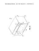
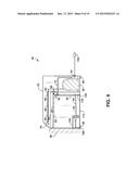
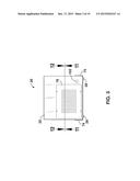
6. The appliance of claim 1, comprising a refrigeration unit for cooling the inner volume of the appliance after the defrost cycle.
7. The appliance of claim 6, comprising a pump coupled to the water source and the water manifold, wherein the water source is a tank having a fixed volume, the pump circulates water in a continuous cycle between the tank and the manifold, and wherein the defrost cycle has a finish time, the finish time determined based on a temperature of the water being recycled within the appliance.
Description:
BACKGROUND OF THE INVENTION
[0001] The present application relates to defrost appliances, in particular to defrost appliances for use in domestic, restaurant and other settings for defrosting food conveniently and safely.
[0002] A common situation, existing today, is that steaks purchased a few weeks previously are waiting in the freezer to be prepared. But first, the steaks have to be defrosted. Some leave the steaks on the counter all day, for example, from the time the person leaves for work until the person returns which is unsafe and can cause illness.
[0003] Today there are three other common choices for thawing any type of food. They are refrigerator thawing, cold water thawing and microwave thawing. All of these methods have further disadvantages.
[0004] Refrigerator thawing has the disadvantage of having to wait a long time for the food to defrost. Most of the time, with most foods, it takes a full day or longer to defrost food left in the refrigerator.
[0005] Cold water thawing requires a lot of attention. The food must be submerged in the water at the right temperature and the water has to be changed every thirty minutes or so to insure the water stays sufficiently cold to prevent bacterial growth. The food has to be cooked immediately after thawing occurs.
[0006] Microwave thawing requires diligent setting of the defrost controls to insure the outer edges of the food do no become cooked while the inner remainder is still frozen.
[0007] While it may be tempting to use any of the above-mentioned methods, the problem ultimately exists. With these methods, for the most part, the outer layer of food can potentially sit between the bacteria breeding temperature of 40 degrees and 140 degrees Fahrenheit for far to long to be safe.
[0008] Accordingly there is a need for a defrost appliance which over comes the limitations of the methods noted above and which provides a quick, efficient, safe, controlled, easy to use way for defrosting frozen food.
SUMMARY OF THE INVENTION
[0009] Additional aspects of the present invention will be apparent in view of the description which follows. A defrost appliance as described herewith.
BRIEF DESCRIPTION OF THE FIGURES
[0010] FIG. 1 is a perspective view of one side and the front of the defrost appliance according to one embodiment;
[0011] FIG. 2 is a front view thereof;
[0012] FIG. 3 is a back view thereof;
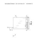
[0013] FIG. 4 is a left side view thereof;
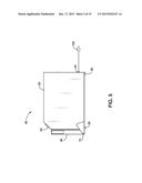
[0014] FIG. 5 is a right side view thereof;
[0015] FIG. 6 is a top view thereof;
[0016] FIG. 7 is a bottom view thereof;
[0017] FIG. 8 is a perspective view of one side and the front of the invention according to one embodiment;
[0018] FIG. 9 is a section view taken from FIG. 2.
[0019] FIG. 10 is a section view taken from FIG. 2.
[0020] FIG. 11 is a section view taken from FIG. 3.
[0021] FIG. 12 is a section view taken from FIG. 3.
[0022] FIG. 13 is a section view taken from FIG. 4.
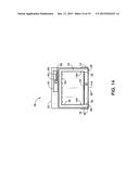
[0023] FIG. 14 is a section view taken from FIG. 4.
[0024] FIG. 15 is a section view taken from FIG. 12.
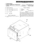
[0025] FIG. 16 is an exploded view of FIG. 1.
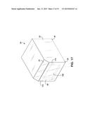
[0026] FIG. 17 is a perspective view of one side and the front of the invention according to a second embodiment.
[0027] FIG. 18 is a perspective view of one side and the front of the invention according to a third embodiment.
[0028] FIG. 19 is a perspective view of one side and the front of the invention according to a fourth embodiment.
DETAILED DESCRIPTION OF THE INVENTION
[0029] Subject matter will now be described more fully hereinafter with reference to the accompanying drawings, which form a part hereof, and which show, by way of illustration, exemplary embodiments in which the invention may be practiced. Subject matter may, however, be embodied in a variety of different forms and, therefore, covered or claimed subject matter is intended to be construed as not being limited to any example embodiments set forth herein; example embodiments are provided merely to be illustrative. It is to be understood that other embodiments may be utilized and structural changes may be made without departing from the scope of the present invention. Likewise, a reasonably broad scope for claimed or covered subject matter is intended. The following detailed description is, therefore, not intended to be taken in a limiting sense.
[0030] Throughout the specification and claims, terms may have nuanced meanings suggested or implied in context beyond an explicitly stated meaning. Likewise, the phrase "in one embodiment" as used herein does not necessarily refer to the same embodiment and the phrase "in another embodiment" as used herein does not necessarily refer to a different embodiment. It is intended, for example, that claimed subject matter include combinations of exemplary embodiments in whole or in part.
[0031] Referring to FIG. 1 through FIG. 17 of the defrost appliance 20 according to at least one embodiment includes the outside shell 22 and the inner shell 34, comprised of about 0.047 inch thick sheet metal, plastic, composite or other suitable material for forming a cabinet like structure.
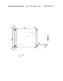
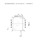
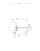
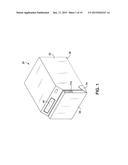
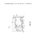
[0032] An outside shell 22 measures about 14.0 inches high by about 15.63 inches wide by about 21.37 inches long externally and is beveled at about 45 degrees on its front upper corner. Outside shell 22 houses the components of defrost appliance 20 that provide the functionality described herein. The display screen 24 is housed in the beveled surface and contains electronic or manual control means to operate defrost appliance 20. Control means can be such functions as on and off, timing cycles, temperature control, flow rates, light emitting device control and other functions. The compressor cover 78, made from like materials, serves as an access panel to the working components and fastens to the back of defrost appliance 20. The power cord 102 protrudes from the back of outside shell 22 and is affixed to outside shell 22 by the cord clamp 44 as a means to conduct energy into defrost appliance 20 from conventional power sources. An outer shell 22 is supported by bottom plate 26 comprised of about 0.094 inches thick sheet metal, plastic, composite or other suitable material for forming a platform. One or more supports 28 comprised of elastomer material are affixed to the bottom of plate 26 to absorb vibration from the compressor 30.
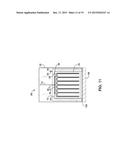
[0033] An inner shell 34 measures about 8.6 inches high by about 12.53 inches wide by about 12.50 inches long internally and is surrounded by the insulation 70 such as foam or fiber insulation 70. Inner shell 34 creates an inner volume that serves as the working chamber of defrost appliance 20. The drip pan 53 is a rectangular tray that sits at the bottom of inner shell 34 and holds about a gallon of liquid, such as water. The drip pan frame 52 is situated at the top of drip pan 53 and supports the perforated drip pan covers 54 that are removable and rest at about one degree slant to horizontal. An inner shell 34 houses the ultra violet light 42, the temperature probe 38, the exchanger 40 and the water manifold 50.
[0034] The door 56 is comprised of about 0.047 inch thick sheet metal, plastic, composite or other suitable material for forming a door structure. A door 56 measures about 11.52 inches high by about 15.63 inches wide by about 1.75 inches thick externally. The magnetic door seal 106 surrounds the inside of door 56 and affixes to outer shell 22 when in the closed position. The interior of door 56 can be filled with insulation 70. In other embodiments a door seal can be of mechanical means to secure door 56 to outside shell 22. One or more of the door stops 104 can be affixed to door 56 and the inside of inner shell 34 to hold door 56 at a ninety degree angle to the front of defrost appliance 20 when in an open position. One or more of the hinges 58 connect a door 56 to an outer shell 22 and can be concealed by the hinge covers 74. A door 56 can be opened and closed by use of the door handle 110. There can be one or more door handles 110 that are integral to the structure of door 56 or surface mounted on door 56.
[0035] A defrost appliance 20 is operated by opening a door 56, lifting out one or more removable drip pan covers 54 from the top of drip pan frame 52 and filling drip pan 53 with about a gallon of liquid such as water. Water may be filled to an appropriate amount as specified by a water level indicator in drip pan 53. According to one embodiment, drip pan 53 may be removable that would enable easier access to the drip pan to fill with water. In another embodiment, a direct water line from a domestic water source may be configured to feed into the drip pan 53 or a water tank. Drip pan covers 54 are then returned to their place on top of the drip pan frame 52, located above drip pan 53 creating the drip pan assembly within the inner volume of the applicant 20. Frozen food, in a closed plastic bag, is then placed in a centrally located position in the interior of inner shell 34 on the drip pan assembly. Display screen 24 is then set to the appropriate settings for the frozen food being defrosted and the defrosting cycle begins by pressing start on display screen 24. According to an alternative embodiment, drip pan 52 may include a smart scale configured to weigh the food to be defrosted and automatically calculate the time needed to defrost said food. This function may be enabled by selecting a "smart" defrost setting on display screen 24. The display wires 60 and the thermostat wires 62 carry and exchange command signals to respective compressor 30, pump 32, ultra violet light 42, temperature probe 38, power cord 102 and any other electronic devices that may be present in the defrost appliance 20 system.
[0036] The interior of inner shell 34 is kept cold by compressor 30 having the compressor electrical junction 80 connected to power cord 102 by cord clamp 44 and its internal electrical line connections covered by access compressor electrical cover 82. Compressor line 72 carries coolant to and from the compressor 30 to heat exchanger 40 to cool interior of inner shell 34.
[0037] Liquid in drip pan 53 flows through the pan fitting 68 into tank hose 36 by means of pump 32 which elevates liquid through manifold hose 46 to water manifold 50. Liquid rains from manifold 50 falling on frozen food to aid in the defrosting process and returns to drip pan 53 for continuous recycling of the liquid in a closed system by pump 32, which is a water saving feature of the appliance. Alternatively, the water may be fed to the manifold 50 directly or indirectly (e.g., bypassed through the heating element and thermostat) from a domestic water supply that provides a continuous stream of water for cool water defrosting. In this instance, the apparatus may also have a drain coupled to the domestic water collection system (e.g., a sewer system) to handle the effluent. A bowl accessory may be used in conjunction with the defrost appliance 20. The bowl accessory may include holes on the bottom that rest upon the drip pan 53 or drip pan covers 54. The holes located at the bottom of the bowl allows water to fill up the bowl in order to submerge food product under water, but yet allow water to drip back into the drip pan 53 along with water from over flowing in the bowl. The flow rate of the water dripping from the bowl can be slow enough to fill the bowl, but allow water enough time to build up for over flow.
[0038] The water filter 112 may or may not be included in the system to manage water quality, filter out minerals and preform other filtering functions. In one embodiment, a bacteria or pH sensor may be configured in drip pan 53 to monitor the cleanliness of the water to enabled continued usage of the water for additional defrost cycles. An auto-clean (self clean) function may perform a cleaning cycle to clear the drip pan 53 from residue buildup. The drain 114 may or may not be included in drip pan 54 to aid in removing liquid when necessary. A drain can be a valve, hose, plug or any other means suitable for quickly removing liquid from drip pan 54. Additionally, the defrost appliance 20 may include an auto fill/drain feature that can fill the drip pan 54 with fresh water after each defrosting cycle, or when bacteria or pH sensors deem it necessary to change water. During the process of circulating a room temperature liquid, a liquid's temperature is subject to change, primarily cooling, as a liquid travels trough temperature controlled inner shell 34. The second temperature probe 118 is installed in drip pan 53 to monitor the temperature of the liquid in a drip pan 53. As the temperature of the liquid in drip pan 53 lowers, the heating element 120 is engaged by a second temperature probe 118 and other system controls to raise the temperature of a liquid to room temperature or other appropriate temperature designated by the system.
[0039] Once the defrost cycle is complete display screen 24 will visibly and or audibly indicate frozen food is properly defrosted. Upon completion of the defrost cycle defrost appliance 20 refrigeration holds the unthawed food at standard recommended refrigeration temperature. At this time the ultra violet light 42 turns on to sterilize the inner volume of the applicant 20.
[0040] Referring more specifically to FIG. 17 through FIG. 19 perspective views of one side and the front of the invention according to other embodiments. A door 56 can be recessed into outside shell 22. In this embodiment one or more hinges 58 are concealed from external view. The front of door 56 may be comprised of tempered glass or translucent plastic as well as the forty five degreed beveled surface at the front of outside shell 22 that houses display screen 24. The window 108 may or may not be present in door 56, in these or other embodiments, to aid in viewing into inner shell 34 from outside defrost appliance 20.
[0041] Accordingly a defrost appliance 20 over comes the limitations of other methods of defrosting by having insulation 70 about a closed inner shell 34, providing refrigeration and ultra violet light 42 to control the proliferation of bacteria and circulating liquid via pump 32 raining it down on sealed frozen food to expedite thawing in a refrigerated environment which provides a quick, efficient, safe, controlled, easy to use way for defrosting frozen food.
[0042] While the foregoing invention has been described in some detail for purposes of clarity and understanding, it will be appreciated by one skilled in the art, from a reading of the disclosure, that various changes in form and detail can be made without departing from the true scope of the invention.
User Contributions:
Comment about this patent or add new information about this topic:
Images included with this patent application:
 |  |
 |  |
 |  |
 |  |
 |  |
 |  |
 |  |
 |  |
 |  |
 |  |
| Similar patent applications: | |
| Date | Title |
|---|---|
| 2015-12-03 | Dc brushless motor control system applicable for ac power |
| 2016-01-21 | Maximizing defrost mode in electrified vehicle having dual evaporator and dual heater core climate control system |
| 2016-02-04 | System and method for establishing a relative humidity with a chilled chamber of a refrigerator appliance |
| 2010-06-24 | Domestic appliance |
| 2010-07-08 | Domestic appliance |
| New patent applications in this class: | |
| Date | Title |
|---|---|
| 2017-08-17 | Refrigeration cycle apparatus and air-conditioning apparatus |
| 2016-07-14 | Vehicle air conditioner |
| 2016-07-07 | Vehicle air conditioner |
| 2016-06-23 | Air conditioner |
| 2016-06-23 | Air conditioner |
| Top Inventors for class "Refrigeration" | |
| Rank | Inventor's name |
|---|---|
| 1 | Michael F. Taras |
| 2 | Alexander Lifson |
| 3 | Koji Yamashita |
| 4 | Hiroyuki Morimoto |
| 5 | Patrick J. Boarman |