Patent application title: PNEUMATIC TOOL MOTOR ROTOR WITH THRUST AUGMENTATION EFFECT
Inventors:
Ching-Shun Chang (Taichung City, TW)
IPC8 Class: AF01C1344FI
USPC Class:
418 58
Class name: Rotary expansible chamber devices working member has planetary or planetating movement plural working members or chambers
Publication date: 2015-11-19
Patent application number: 20150330219
Abstract:
A pneumatic tool motor rotor with thrust augmentation effect has a rotor
body in the shape of a three-dimensional cylinder having a circular wall
and two end faces, and the circular wall is circularly arranged with
multiple concave grooves with preset intervals. Motive blades are
configured on the concave grooves, flexible on the radial direction. A
power outputting shaft protrudes from the rotor body. Augmenting concave
parts are formed nearby the concave grooves on the circular wall of the
rotor body and include a wind guiding surface and a pushed augmenting
surface, with the facing direction of the pushed augmenting surface being
the same as or close to that of the motive blades. Between the pushed
augmenting surface and the nearby concave groove, a separating rib is
formed, and the wind guiding surface extends outside from the inner end
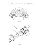
of the pushed augmenting surface and connects with the circular wall.Claims:
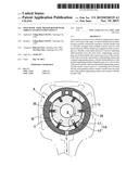
1. A pneumatic tool motor rotor with thrust augmentation effect
comprising: a rotor body, in the shape of a three-dimensional cylinder
having a circular wall and two end faces, and the circular wall is
circularly arranged with multiple concave grooves with preset intervals;
multiple motive blades, configured on the concave grooves formed on the
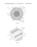
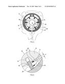
circular wall of the rotor body, flexible on the radial direction; a
power outputting shaft, protruding from one end face of the rotor body;
multiple augmenting concave parts, concavely formed nearby the concave
grooves on the circular wall of the rotor body, wherein, said augmenting
concave parts include a wind guiding surface and a pushed augmenting
surface, with the facing direction of the pushed augmenting surface being
the same as or close to that of the motive blades, moreover, between the
pushed augmenting surface and the nearby concave groove, a separating rib
is formed, and the wind guiding surface extends outside from the inner
end of the pushed augmenting surface and connect with the circular wall;
thus, when the motor rotor in the pneumatic tool is pushed by air
pressure, the pressure receiving area can be enlarged through the pushed
augmenting surface of the augmenting concave parts, so as to enhance the
rotational torque of the motor rotor.
2. The structure defined in claim 1, wherein, between the neighboring concave grooves, two augmenting concave parts are formed with opposite pushed directions, wherein the slanting directions of the wind guiding surfaces of the two augmenting concave parts are opposite of each other, and the pushed augmenting surfaces of the two augmenting concave parts are adjacent to different concave grooves; based on this, in the cases of both normal or reverse rotation of the motor rotor, augmentation can be accomplished through the augmenting concave parts.
3. The structure defined in claim 2, wherein the part between the augmenting concave parts and the two end faces of the rotor body is arranged as local sections with some spacing.
4. The structure defined in claim 2, wherein the augmenting concave parts are arranged as a full section with its two ends going through the rotor body to the two end faces.
5. The structure defined in claim 3, wherein the inside of the rotor body is in a solid style.
6. The structure defined in claim 3, wherein the inside of the rotor body has a hollow chamber, said hollow chamber is arranged to hold a hammering component, so as to form a rotor body with built-in hammering function.
Description:
CROSS-REFERENCE TO RELATED U.S. APPLICATIONS
[0001] Not applicable.
STATEMENT REGARDING FEDERALLY SPONSORED RESEARCH OR DEVELOPMENT
[0002] Not applicable.
NAMES OF PARTIES TO A JOINT RESEARCH AGREEMENT
[0003] Not applicable.
REFERENCE TO AN APPENDIX SUBMITTED ON COMPACT DISC
[0004] Not applicable.
BACKGROUND OF THE INVENTION
[0005] 1. Field of the Invention
[0006] The present invention relates generally to a local structure of pneumatic tools, and more particularly to an innovative structure of a pneumatic tool motor rotor with a thrust augmentation effect.
[0007] 2. Description of Related Art Including Information Disclosed Under 37 CFR 1.97 and 37 CFR 1.98.
[0008] In the structural design of pneumatic tools (such as a pneumatic spanner, pneumatic handle, pneumatic driver, etc.), the main motion part is the motor rotor inside the cylinder with motive blades circularly arranged with preset intervals. The motive blades are pushed by the pressure of the air introduced into the cylinder and drive the motor rotor to rotate, and then the rotation of the motor rotor further drives the tool end (such as socket, driver head fitting bar) of the pneumatic tool to rotate to accomplish its function.
[0009] As the rotary motion of the motor rotor is driven by the air pressure, the overall structural design of the motor rotor is directly related to the driving torque of the pneumatic tool, and is therefore a critical technical concern.
[0010] In the structure of present known pneumatic tools, usually the torque of the driving rotor is only determined by optimization of the air flow path and the area configuration of the blades. However, when the maximum size of the rotor is limited, the maximum area of the blades is also limited. There is not much space and possibility for expansion.
[0011] Some manufacturers have developed a new driving rotor structure with its motive blades formed with concave grooves to accumulate and increase air pressure. In this way, the torque of driving rotor can be enhanced without changing the area configuration of the blades. However, according to investigations, such known structure still has its limitation in actual applications. As the overall area and thickness of the blades of the driving rotor is limited (note: particularly so in the case of small-size pneumatic tool products), removing material from the blades with limited area and thickness to form concave grooves with sufficient air pressure accumulation will obviously affect the structural strength of the blades. Moreover, in the case of driving rotors having a need for torque augmentation in both normal and reverse rotational directions, it is necessary to form the above-mentioned grooves on both sides of the blades. However, as the thickness of the driving rotor blades is usually only about 3 mm, to form concave grooves on both sides of the blades and maintain sufficient thickness between the relative grooves, the depth of the concave grooves can not be large enough for sufficient augmentation effect. Hence, such known structure with air pressure augmentation through rotor blades is still not perfect and needs some improvement.
[0012] Thus, to overcome the aforementioned problems of the prior art, it would be an advancement in the art to provide an improved structure that can significantly improve the efficacy.
[0013] Therefore, the inventor has provided the present invention of practicability after deliberate design and evaluation based on years of experience in the production, development and design of related products.
BRIEF SUMMARY OF THE INVENTION
[0014] The present invention discloses a "pneumatic tool motor rotor with thrust augmentation effect" with an innovative and unique structural design featuring augmenting concave parts arranged between the concave grooves on the circular wall of the rotor body. In contrast to known structures introduced in "prior art", when the motor rotor is pushed by air pressure inside the pneumatic tool, the air pressure receiving area can be expanded through the pushed augmenting surfaces of the augmenting concave parts. Therefore, the present invention has a practical advancement and advantage to effectively enhance the rotational torque of the motor rotor without changing the overall size of the motor rotor. On the other hand, through arrangement of the augmenting concave parts, the present invention makes it possible to remove some material from the rotor body structure and form a strengthening rib structure (i.e. separating rib 50 parts) between the neighboring concave grooves. The lightweight design and enhanced structural strength of the motor rotor obviously constitute another practical advancement and advantage.
[0015] Although the invention has been explained in relation to its preferred embodiment, it is to be understood that many other possible modifications and variations can be made without departing from the spirit and scope of the invention as hereinafter claimed.
BRIEF DESCRIPTION OF THE SEVERAL VIEWS OF THE DRAWINGS
[0016] FIG. 1 is a perspective view of a preferred embodiment of the present invention (note: local components are shown in exploded state).
[0017] FIG. 2 is a plane sectional view of a preferred embodiment of the present invention.
[0018] FIG. 3 shows another embodiment of the augmenting concave parts of the present invention.
[0019] FIG. 4 shows the application state of the present invention.
[0020] FIG. 5 is an enlarged view of Part B in FIG. 4.
[0021] FIG. 6 is an illustrative view of the augmenting concave parts of the present invention with opposite configuration.
[0022] FIG. 7 shows an embodiment of the present invention with the rotor body having a hollow chamber to hold a hammering component.
DETAILED DESCRIPTION OF THE INVENTION
[0023] FIGS. 1 and 2 depict a preferred embodiment of the pneumatic tool motor rotor with thrust augmentation effect. However, such an embodiment is only for the purpose of illustration, and is not intending to limit the scope of patent application.
[0024] Said motor rotor A comprises a rotor body 10, in the shape of a three-dimensional cylinder having a circular wall 11 and two end faces 12, 13, and the circular wall 11 is circularly arranged with multiple concave grooves 14 with preset intervals.
[0025] Multiple motive blades 20 are configured on the concave grooves 14 formed on the circular wall 11 of the rotor body 10, flexible on the radial direction.
[0026] A power outputting shaft 30 protrudes from one end face 12 of the rotor body 10.
[0027] Multiple augmenting concave parts 40 are concavely formed nearby the concave grooves 14 on the circular wall 11 of the rotor body 10, wherein, said augmenting concave parts 40 include a wind guiding surface 41 and a pushed augmenting surface 42, with the facing direction of the pushed augmenting surface 42 being the same as or close to that of the motive blades 20, moreover, between the pushed augmenting surface 42 and the nearby concave groove 14, a separating rib 50 is formed, and the wind guiding surface 41 extends outside from the inner end of the pushed augmenting surface 42 (note: can be configured in the form of slope extension or arc extension) and connect with the circular wall 11.
[0028] Referring to FIGS. 3 and 4, based on the above structural design, when the motor rotor A in the pneumatic tool is pushed by air pressure (as marked by Arrow W), the pressure receiving area (marked by L1 in FIG. 4) can be enlarged through the pushed augmenting surface 42 of the augmenting concave parts 40, so as to effectively increase the air pushing force received by the rotor body 10, and consequently enhance the rotational torque of the motor rotor A.
[0029] Referring to FIG. 6, between the neighboring concave grooves 14, two augmenting concave parts 40 can be formed with opposite pushed directions, wherein the slanting directions of the wind guiding surfaces 41 of the two augmenting concave parts 40 are opposite of each other, and the pushed augmenting surfaces 42 of the two augmenting concave parts 40 are adjacent to different concave grooves 14. Based on this, in the cases of both normal or reverse rotation of the motor rotor A, augmentation can be accomplished through the augmenting concave parts 40 (as marked by Arrows L2 and L3 in FIG. 6).
[0030] Referring to FIG. 1, the part between the augmenting concave parts 40 and the two end faces 12, 13 of the rotor body 10 can be arranged as local sections with some spacing (L4).
[0031] Referring to FIG. 3, the augmenting concave parts 40 can also be arranged as a full section with its two ends going through the rotor body 10 to the two end faces 12, 13.
[0032] Referring to FIG. 2, the inside of the rotor body 10 can be in a solid style.
[0033] Further, referring to FIG. 7, the inside of the rotor body 10B can also have a hollow chamber 60, said hollow chamber 60 can hold a hammering component 70, so as to form a rotor body 10 with built-in hammering function. The structural detail of the hammering component 70 is a known technique not covered by the present invention, and is therefore not introduced herein.
User Contributions:
Comment about this patent or add new information about this topic:
Images included with this patent application:
 |  |
 |  |
 |
| Similar patent applications: | |
| Date | Title |
|---|---|
| 2016-05-19 | Pump integrated with two independently driven prime movers |
| 2016-05-12 | Compressor with liquid injection cooling |
| 2015-05-28 | Reversible pneumatic vane motor |
| 2015-12-17 | Shroud for rotary engine |
| 2015-12-17 | Oil pump for automatic transmission |
| New patent applications in this class: | |
| Date | Title |
|---|---|
| 2019-05-16 | Six-stroke rotary-vane internal combustion engine |
| 2016-07-07 | Rotary motor with geared transmission for use of compressible media drive |
| 2011-10-27 | Screw compressor with asymmetric ports |
| 2009-09-24 | Rotary compressor |
| 2008-11-27 | Multistage compression type rotary compressor |
| New patent applications from these inventors: | |
| Date | Title |
|---|---|
| 2017-02-16 | Pneumatic tool motor having an internal hammering device |
| 2015-01-15 | Pneumatic motor with built-in striker mechanism |
| 2013-08-08 | Cylinder dividing mechanism of a pneumatic tool |
| 2011-09-29 | Impact hammer with pre-pressing damping and buffering effect |
| 2011-09-29 | Integrated cylinder and reversing assembly module of a reciprocating pneumatic tool |
| Top Inventors for class "Rotary expansible chamber devices" | |
| Rank | Inventor's name |
|---|---|
| 1 | Byeongchul Lee |
| 2 | Masanori Masuda |
| 3 | Robert C. Stover |
| 4 | Masao Akei |
| 5 | Rene Schepp |