Patent application title: BATHROOM RACK
Inventors:
Cheng-I Hsieh (Changhua, TW)
Tung-Shu Yao (Changhua, TW)
Assignees:
JIN JU HAN INDUSTRIAL CORPORATION
IPC8 Class: AA47B9606FI
USPC Class:
211 8801
Class name: Specially mounted wall or window tray
Publication date: 2015-11-19
Patent application number: 20150327681
Abstract:
A bathroom rack may include a main body and at least two positioning
units. The main body has a hanging portion at a rear portion thereof.
Each of the positioning unit has a connecting head, a screw, and a cover.
The connecting head has a first end and a second end, and the second end
has a threaded connecting section. The cover has an inner hole that has a
threaded connecting portion corresponding to the connecting section. A
notch is formed at a periphery near a center portion of the positioning
unit, and a locking hole toward the direction of the first end is located
at a rear end of the notch, and the main body is configured to
horizontally slide into the notch of the connecting head through the
hanging portion to engage with the connecting head.Claims:
1. A bathroom rack comprising: a main body having a hanging portion at a
rear portion thereof; and at least two positioning units, each having a
connecting head, a screw, and a cover, wherein the connecting head has a
first end and a second end, and the second end has a threaded connecting
section, and the cover has an inner hole that has a threaded connecting
portion corresponding to the connecting section, wherein a notch is
formed at a periphery near a center portion of the positioning unit, and
a locking hole toward the direction of the first end is located at a rear
end of the notch, and wherein the screw is inserted into the locking hole
of the connecting head and be secured in a plastic receiving unit, and
through the pressure applied from the screw, the connecting head is
securely attached to the wall surface through the first end; the main
body is configured to horizontally slide into the notch of the connecting
head through the hanging portion to engage with the connecting head, and
when the connecting section of the cover engages with the connecting
portion to connect to the second end of the connecting head, the main
body is securely positioned by the connecting head and cover.
2. The bathroom rack of claim 1, wherein the main body is a basket.
3. The bathroom rack of claim 2, wherein a stick extends downwardly from a lateral side of the basket.
4. The bathroom rack of claim 2, wherein a receiving space is formed underneath the basket.
5. The bathroom rack of claim 1, wherein a hook portion is formed at a lower portion of the hanging portion.
6. The bathroom rack of claim 1, wherein the diameter of the second end is smaller than the first end.
7. The bathroom rack of claim 1, wherein the connecting portion and connecting section are engaged with each other through the threads thereof.
8. The bathroom rack of claim 1, wherein the main body is secured in the notch, an opening of which can be sealed by the cover to prevent the main body from falling off when external force is applied to the main body.
Description:
FIELD OF THE INVENTION
[0001] The present invention relates to a bathroom rack, and more particularly to a bathroom rack that can be more stably secured to prevent from falling off when external force is applied.
BACKGROUND OF THE INVENTION
[0002] Conventionally, a bathroom rack has one or more locking holes on the rack structure to receive the screws, which can be drilled into the wall to secure the rack. When in use, toiletries are placed and organized on the rack.
[0003] However, the screws can be seen with the bathroom rack, which reduces the aesthetic value of the bathroom rack. Also, the bathroom rack structure is not stable. Therefore, there remains a need for a new and improved bathroom rack to overcome the problems presented above.
SUMMARY OF THE INVENTION
[0004] The present invention provides a bathroom rack that includes a main body and at least two positioning units. The positioning unit has a connecting head, a screw, and a cover. The main body has a basket and hanging portion. A stick extends downwardly from a lateral side of the basket, or a receiving space is formed underneath the basket. The connecting head has a first end and a second end with a reduced size, and the second end has a threaded connecting section. A notch is formed at a periphery near a center portion of the positioning unit, and a locking hole toward the direction of the first end is located at a rear end of the notch. The cover has an inner hole that has a threaded connecting portion.
[0005] Comparing with conventional bathroom racks, the present invention is advantageous because (i) the cover can cover the screw to increase the aesthetic value of the main body, and the cover can also be used as a decorative unit; and (ii) the main body is secured in the notch, the opening of which can be sealed by the cover to prevent the main body from falling off when external force is applied to the main body.
BRIEF DESCRIPTION OF THE DRAWINGS
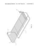
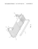
[0006] FIG. 1 is a three-dimensional view of the bathroom rack in the present invention.
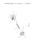
[0007] FIG. 2 is an exploded view of the bathroom rack in the present invention.
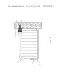
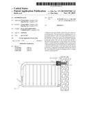
[0008] FIG. 3 is a sectional view of the bathroom rack of the present invention when being secured against the wall.
[0009] FIG. 4 is a three-dimensional view of the bathroom rack of the present invention when being secured against the wall.
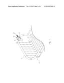
[0010] FIG. 5 is a schematic view of the bathroom rack of the present invention with the stick.
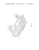
[0011] FIG. 6 is a schematic view of the bathroom rack of the present invention with the receiving space.
DETAILED DESCRIPTION OF THE INVENTION
[0012] The detailed description set forth below is intended as a description of the presently exemplary device provided in accordance with aspects of the present invention and is not intended to represent the only forms in which the present invention may be prepared or utilized. It is to be understood, rather, that the same or equivalent functions and components may be accomplished by different embodiments that are also intended to be encompassed within the spirit and scope of the invention.
[0013] Unless defined otherwise, all technical and scientific terms used herein have the same meaning as commonly understood to one of ordinary skill in the art to which this invention belongs. Although any methods, devices and materials similar or equivalent to those described can be used in the practice or testing of the invention, the exemplary methods, devices and materials are now described.
[0014] All publications mentioned are incorporated by reference for the purpose of describing and disclosing, for example, the designs and methodologies that are described in the publications that might be used in connection with the presently described invention. The publications listed or discussed above, below and throughout the text are provided solely for their disclosure prior to the filing date of the present application. Nothing herein is to be construed as an admission that the inventors are not entitled to antedate such disclosure by virtue of prior invention.
[0015] In order to further understand the goal, characteristics and effect of the present invention, a number of embodiments along with the drawings are illustrated as following:
[0016] Referring to FIGS. 1 and 4, the present invention provides a bathroom rack that includes a main body (10) and at least two positioning units (20). The positioning unit 20 has a connecting head (21), a screw (22), and a cover (23). The main body (10) has a basket (11) and hanging portion (12). A stick (13) extends downwardly from a lateral side of the basket (11) (see FIG. 5), or a receiving space (14) is formed underneath the basket (11) (see FIG. 6). The connecting head (21) has a first end (211) and a second end (212) with a reduced size, and the second end (212) has a threaded connecting section (213). A notch (214) is formed at a periphery near a center portion of the positioning unit (20), and a locking hole (215) toward the direction of the first end (211) is located at a rear end of the notch (214). The cover (23) has an inner hole (231) that has a threaded connecting portion (232).
[0017] In one embodiment, a hook portion (121) is formed at a lower portion of the hanging portion (12).
[0018] Referring to FIGS. 3 to 6, when in use, the user has to drill holes on the wall and inserts a plastic receiving unit (30), so the screw (22) can insert into the locking hole (215) of the connecting head (21) and be secured in the plastic receiving unit (30). Through the pressure from the screw (22), the connecting head (21) can securely attach to the wall surface through the first end (211). The main body (10) is configured to horizontally slide into the notch (214) of the connecting head (21) through the hanging portion (12) to engage with the connecting head (21). When the connecting section (213) of the cover (23) engages with the connecting portion (232) to connect to the second end (212) of the connecting head (21), the main body (10) can be securely positioned by the connecting head (21) and cover (23). It is noted that the cover (23) can not only cover the screw (22) but also seal the opening of the notch (214).
[0019] Comparing with conventional bathroom racks, the present invention is advantageous because (i) the cover (23) can cover the screw (22) to increase the aesthetic value of the main body (10), and the cover (23) can also be used as a decorative unit; and (ii) the main body (10) is secured in the notch (214), the opening of which can be sealed by the cover (23) to prevent the main body (10) from falling off when external force is applied to the main body (10).
[0020] Having described the invention by the description and illustrations above, it should be understood that these are exemplary of the invention and are not to be considered as limiting. Accordingly, the invention is not to be considered as limited by the foregoing description, but includes any equivalents.
User Contributions:
Comment about this patent or add new information about this topic:
Images included with this patent application:
 |  |
 |  |
 |  |
 |
| New patent applications in this class: | |
| Date | Title |
|---|---|
| 2016-04-07 | A corner caddy |
| 2014-10-02 | Storage system for utlizing space between wall studs |
| 2014-09-18 | System and method for assembling and using assisted storage |
| 2014-08-28 | Shelving system |
| 2012-10-11 | Modular display and storage tray system |
| Top Inventors for class "Supports: racks" | |
| Rank | Inventor's name |
|---|---|
| 1 | Stephen N. Hardy |
| 2 | Wen-Tsan Wang |
| 3 | Gregory M. Bird |
| 4 | Shane Obitts |
| 5 | Kaveh Didehvar |