Patent application title: Witness Material and Method for Monitoring the Environmental History of an Object
Inventors:
Gary E. Georgeson (Tacoma, WA, US)
Gary E. Georgeson (Tacoma, WA, US)
Morteza Safai (New Castle, WA, US)
Assignees:
The Boeing Company
IPC8 Class: AG01L124FI
USPC Class:
116201
Class name: Signals and indicators indicators methods
Publication date: 2015-10-29
Patent application number: 20150308907
Abstract:
A witness material for monitoring an environmental history of an object
may include a material containing a dye of a type that fluoresces in
response to actinic radiation in one or both of a shift in color and a
change in intensity when subjected to a predetermined stress above a
predetermined level; and the material forming a coating on one or more of
an outer container for the object, an inner container for the object, a
tape that is applied to an outer container for the object, a tape that is
applied to an inner container for the object, a shrink wrap enclosing the
object, an outer surface of the object, and an inner surface of the
object.Claims:
1. A witness material for monitoring an environmental history of an
object, the witness material comprising: a material containing a dye of a
type that fluoresces in response to actinic radiation in one or both of a
shift in color and a change in intensity when subjected to a
predetermined stress above a predetermined level; and the material
forming a coating on one or more of an outer container for the object, an
inner container for the object, a tape that is applied to an outer
container for the object, a tape that is applied to an inner container
for the object, a shrink wrap enclosing the object, an outer surface of
the object, and an inner surface of the object.
2. The witness material of claim 1, wherein the predetermined stress is one or both of temperature and impact.
3. The witness material of claim 1, wherein the predetermined stress is temperature, and the material contains a dye of a type that fluoresces in response to actinic radiation in one or both of a shift in color and a change in intensity when subjected to the predetermined stress above the predetermined level for a predetermined time interval.
4. The witness material of claim 1, wherein the dye is of a type that fluoresces in response to actinic radiation other than visible light.
5. The witness material of claim 1, wherein the actinic radiation is ultraviolet light.
6. The witness material of claim 1, wherein the material includes a resin containing the dye.
7. The witness material of claim 1, wherein the dye is selected from a mechanochromatic dye and a thermochromatic dye.
8. The witness material of claim 1, wherein the tape is an adhesively backed tape.
9. The witness material of claim 8, wherein the tape is applied to one or both of the outer edges and features of the object.
10. The witness material of claim 8, wherein the tape is applied to one or both of edges and corners of the outer container for the object.
11. The witness material of claim 8, wherein the tape is applied to one or both of edges and corners of the inner container of the object.
12. The witness material of claim 1, wherein the shrink wrap enclosing the object is a shrink-wrappable sheet.
13. A system using witness material for monitoring an environmental history of an object, the system comprising: a material containing a dye of a type that fluoresces in response to actinic radiation in one or both of a shift in color and a change in intensity when subjected to a predetermined stress above a predetermined level; the material forming a coating on one or more of an outer container for the object, an inner container for the object, a tape that is applied to an outer container for the object, a tape that is applied to an inner container for the object, a shrink wrap enclosing the object, an outer surface of the object, and an inner surface of the object; and a source of the actinic radiation, the source configured to direct the actinic radiation on the coating after a predetermined event.
14. The system of claim 13, wherein the source of actinic radiation is an ultraviolet light.
15. The system of claim 13, wherein the predetermined event is selected from transportation of the object and storage of the object.
16. The system of claim 13, further comprising a device for recording the one or both of the shift in color and the change in intensity when the material fluoresces in response to the actinic radiation after the predetermined event, the device for recording including one or both of a camera and a video camera.
17. The system of claim 16, wherein the device for recording includes a component for measuring the one or both of shift in color and the change in intensity, the component selected from image analysis software and a fluorometer.
18. A method for monitoring an environmental history of an object, the method comprising: providing a material containing a dye of a type that fluoresces in response to actinic radiation in one or both of a shift in color and a change in intensity when subjected to a predetermined stress above a predetermined level; and forming a coating of the material on one or more of an outer container for the object, an inner container for the object, a tape that is applied to an outer container for the object, a tape that is applied to an inner container for the object, a shrink wrap enclosing the object, an outer surface of the object, and an inner surface of the object.
19. The method of claim 18, further comprising irradiating the coating of the material with the actinic radiation to determine whether one or both of the shift in color and the change in intensity have occurred.
20. The method of claim 19, further comprising one or both of documenting and measuring the presence of the one or both of a shift in color and a change in intensity in the material after a predetermined event.
Description:
TECHNICAL FIELD
[0001] The present invention relates to non-destructive inspection techniques for detecting barely visible impact damage, and more particularly, to non-destructive inspection techniques that utilize a witness material that changes properties in response to an applied stress.
BACKGROUND
[0002] Objects that are shipped or stored in containers may be damaged by stress applied externally to the container. Such externally applied stress may take the form of one or more of rough handling, dropping, and bumping the container. Externally applied stress also may take the form of thermal cycles in which the container is subjected to extended periods of temperatures sufficiently high to damage the objects in the container or package. Damaging thermal cycles also may take the form of localized heating of less than the entire container to a temperature and for a time sufficient to damage the objects within.
[0003] Objects such as sensitive electronic instruments may be vulnerable to external stresses resulting from such rough handling, dropping and bumping, and also sensitive to exposure to high temperatures. Sensitive objects may include items such as chemicals, paints, biological substances, and live animals such as fish. These objects must be maintained within a relatively narrow temperature range when transported, and also may be susceptible to damage resulting from impacts to the containers in which they are shipped.
[0004] Such objects may arrive damaged to the recipient, but the exposure of the shipped or stored objects to damaging impacts, or to extended high temperatures during transportation or storage of the object, may not be readily apparent from an inspection of the object or the container. Consequently, it may difficult to prove that damage to the object within the container was sustained during the transportation of the object in the container, as opposed to the object being shipped in an original, damaged condition. It is therefore difficult in such circumstances to file a claim with a transporter of the object because there is no evidence that the damaging impact or damaging high temperature occurred during shipment.
[0005] Accordingly, there is a need for a non-destructive inspection technique that may readily and inexpensively indicate whether an object is subjected to stresses in the nature of impacts and/or damaging high temperatures during shipment.
SUMMARY
[0006] In an embodiment, a witness material for monitoring an environmental history of an object may include a material containing a dye of a type that fluoresces in response to actinic radiation in one or both of a shift in color and a change in intensity when subjected to a predetermined stress above a predetermined level; and the material forming a coating on one or more of an outer container for the object, an inner container for the object, a tape that is applied to an outer container for the object, a tape that is applied to an inner container for the object, a shrink wrap enclosing the object, an outer surface of the object, and an inner surface of the object.
[0007] In another embodiment, a system using witness material for monitoring an environmental history of an object may include a material containing a dye of a type that fluoresces in response to actinic radiation in or both of a shift in color and a change in intensity when subjected to a predetermined stress above a predetermined level; the material forming a coating on one or more of an outer container for the object, an inner container for the object, a tape that is applied to an outer container for the object, a tape that is applied to an inner container for the object, a shrink wrap enclosing the object, an outer surface of the object, and an inner surface of the object; and a source of the actinic radiation, the source configured to direct the actinic radiation on the coating after a predetermined event.
[0008] In yet another embodiment, a method for monitoring an environmental history of an object may include providing a material containing a dye of a type that fluoresces in response to actinic radiation in one or both of a shift in color and a change in intensity when subjected to a predetermined stress above a predetermined level; and forming a coating of the material on one or more of an outer container for the object, an inner container for the object, a tape that is applied to an outer container for the object, a tape that is applied to an inner container for the object, a shrink wrap enclosing the object, an outer surface of the object, and an inner surface of the object.
[0009] Other objects and advantages of the disclosed witness material and method for monitoring the environmental history of an object will be apparent from the following description, the accompanying drawings, and the appended claims.
BRIEF DESCRIPTION OF THE DRAWINGS
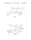
[0010] FIG. 1 is a schematic view of a witness material for monitoring an environmental history of an object, in which the witness material is in the form of a tape or shrink wrap sheet having a dye sprayed upon a surface of the tape or shrink wrap sheet;
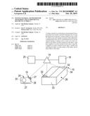
[0011] FIG. 2 is a schematic view of a witness material for monitoring an environmental history of an object in which the material containing a dye is applied to an object and a container for the object;
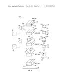
[0012] FIG. 3 is a schematic flow chart showing the process of transporting an object in which the object and/or a container for the object is coated with the disclosed witness material; and
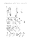
[0013] FIG. 4 is a schematic showing the process of directing actinic radiation on the witness material after the preparation and transportation depicted in FIG. 3.
DETAILED DESCRIPTION
[0014] As shown in FIG. 1, in one embodiment, the witness material for monitoring an environmental history of an object, generally designated 10, may be in the form of a tape 12 that is sprayed by a sprayer 14 to have a pattern or coating 16 of a material containing a dye or probe of a type that fluoresces in response to actinic radiation in one or both of a shift in color and a change in intensity when subjected to a predetermined stress above a predetermined level. In an embodiment, the coating 16 may include a mechanochromatic dye that is supplied to the sprayer from a source 18 of mechanochromatic dye. In an embodiment, the coating 16 may include a thermochromatic dye supplied to the sprayer 14 from a source 20 of thermochromatic dye. In other embodiments, the coating 16 may comprise a combination of a mechanochromatic dye and a thermochromatic dye.
[0015] In an embodiment, the source 18 may be a source of mechanochromatic dye obtainable under the brand AJNDE16, and the thermochromatic dye from source 20 may be obtained under the brand AJNDE17. Both AJNDE16 and AJNDE17 may be obtained from Soluxra, LLC located in Seattle, Wash. Other dyes or probes may be utilized, such as AJNDE30, AJNDE31, AJNDE32, AJNDE33 and AJNDE34, all available from the aforementioned Soluxra, LLC.
[0016] In an embodiment, the tape 12 may be an adhesive-backed tape. In another embodiment, the tape 12 may take the form of a sheet of shrink wrap material. As will be described, the tape 12 containing the coating 16, collectively referred to as a witness material or witness tape 22, may be applied to an object and/or a container for an object to be shipped or stored.
[0017] As shown in FIG. 2, in another embodiment the witness material 10 may be formed by spraying a coating 27 of witness material 10 in the form of mechanochromatic and/or thermochromatic dye from sources 18, 20, respectively, from the sprayer 14 on an object, generally designated 24, or a container, generally designated 26. The object 24 may be an object that is to be shipped and/or stored, and the container 26 may be a container for the object to be shipped and/or stored. Although container 26 is depicted as a box with flaps, the container may be any type of container, including a drum, an insulated foam chest, a cardboard box, a cardboard tube, a corrugated box, a plastic bag, and a bag or envelope made of Tyvek® (a trademark of E. I. du Pont de Nemours and Company). The coating 27 of witness material 10 may be applied to an external surface 28 of the object 24 to be shipped or stored, and/or to an internal surface 30 of the object. The coating 27 may be applied to the entire external and/or internal surfaces 28, 30 of the object 24, or to a selected portion or to selected portions of the external and/or internal surfaces. For example, the coating 27 may be applied to a selected external or internal corner or projection of the object 24, and/or to a selected external or internal edge of the object. The external or internal corner or edge of the object 24 may be selected as likely locations for sustaining a predetermined external stress, such as an impact or localized heating above a predetermined level.
[0018] Similarly, a coating 32 of witness material 10 may be applied to an external surface 33 of a container 26, or to an internal surface 34 of the container. The coating 32 may be applied to the entire external and/or internal surfaces 33, 34 of the container 26, or to a selected portion or portions of the external and/or internal surfaces, such as corners and/or edges of the container. Other locations on the object 24 and container 26 may be selected to receive coatings 27, 32 of witness material 10 and not depart from the scope of the disclosure. The external or internal corner or edge of the container 26 may be selected as likely locations for sustaining a predetermined external stress, such as an impact or localized heating above a predetermined level.
[0019] In an embodiment, the coatings 16, 27, and 32 of thermochromatic and/or mechanochromatic dye preferably are of a type that fluoresces in response to actinic radiation other than visible light. In a particular embodiment, the dyes AJNDE16 and AJNDE17 may be employed either separately, alternatively, in combination, or each in discrete areas on the object 28 or container 26. Such dyes may fluoresce in response to actinic radiation in the form of ultraviolet light. Also in an embodiment, the dye or dyes may be applied in the form of any one of the coatings 16, 27, and 32 embodied in a resin. In a particular embodiment, the resin may comprise di-glycidyl ether of bisphenol-A (DGEBA) with diethylenetriamine (DETA) as a curing agent. In an embodiment, the coatings 16, 27, 32 of witness material may contain a dye of a type that fluoresces in response to actinic radiation in one or both of a shift in color and a change in intensity when subjected to the predetermined stress, such as impact or heating, above a predetermined level for a predetermined time interval (in the case of a thermochromatic dye).
[0020] As shown in FIG. 3, the system, generally designated 100, for utilizing the witness material 10 may take many forms. In one form, the object 24 to be transported and/or stored does not receive a coating of witness material 10 and may be placed in a container 26A in which the outer surface 33 receives the tape 22 described with reference to FIG. 1. Application of the tape 22 may occur at the time the object 24 is packed within the container 26A, or the tape may be applied to the container 26A prior to packing In one particular embodiment, an inventory of containers 26A may be maintained, each having tape 22, and used when needed. The tape 22 may be applied to selected areas of the container 26A, such as the corners and/or outer edges of the container 26A. In other embodiments, the tape 22 may be applied to flat surfaces of the outer surface 33 of the container 26A.
[0021] In another aspect of the system 100, a container 26B may be fitted with the witness tape 22 applied to an interior surface 38. The tape 22 may be applied to edges, corners, or flat surfaces of the interior surface 38. Witness tape 22 may be applied either at or prior to the time the object 24 is packed in container 26B. In another aspect of the system 100, a container 26C may receive a coating 32 of the witness material 10 sprayed on an exterior surface 40 thereof, and in addition, or alternatively, may receive a coating 32 on an interior surface 42. Coatings 32 may be applied at the time of packing the containers 26C, or prior to packing and the containers 26C and kept on hand. The coatings 32 may be applied by a spray device such as spray device 14 described with reference to FIG. 2, and may receive either thermochromatic dye, mechanochromatic dye, or a combination of both. In another aspect of the system 100, the container 26D may be wrapped in a shrink wrap 44 that has been sprayed with the witness material 16, as described with reference to FIG. 1.
[0022] In another aspect of the system 100, the object 24A itself may receive witness tape 22 at corners and projecting surfaces of the outer surface or surfaces 46 of the object. In another aspect of the system 100, the object 24B may receive witness tape 22 applied to an interior surface or surfaces 48. In yet another aspect of the system 100, the object 24C may be shrink wrapped with a sheet of shrink wrap 22 that has been coated with a coating 16 of witness material. The coating 22 may cover all of the sheet of shrink wrap 22, or only selected portions of the sheet.
[0023] In another aspect of the system 100, the object 24D may itself be spray coated with a coating 27 of witness material 16 on an external surface 28, or selected portions of the external surface. In still another aspect of the system 100, object 24E may have a coating 27 of witness material on an internal surface 30. The coatings 27, 30 on the external and/or internal surfaces 28, 30 may cover the entire surfaces, or selected portions of the surfaces. Objects 24A-24E may be treated with witness material 10 at the time of packing, or earlier, as at the time of assembly.
[0024] Each of the objects 24, 24A, 24B, 24C, 24D, and 24E may be placed within and packed in any one of the containers 26A, 26B, 26C, and 26D. Such packing may include adding packing material around the object 24, 24A-24E, then sealing the container 26, 26A-26D. Because the objects 24A-24E themselves may contain witness material 10 in the form of tapes 22 or in coatings 27, 30, it may not be necessary to treat the container 26 with witness material if such objects are packed in it.
[0025] In the embodiment of the system 100 shown, the containers 26A-26D may themselves serve as shipping or storage containers. In another embodiment of the system 100, containers 26A-26D may serve as internal containers, and may be packed within outer containers 26E, 26F, 26G, and 26H. As with internal containers 26A-26D, outer container 26E may be fitted with witness tape 22 on corners and edges of an external surface 46, and outer container 26F may be fitted with witness tape 22 on corners and edges of an internal surface 48. Outer container 26G may receive a coating 32 on an external surface 50, and/or or a coating 32 on an internal surface 52. Again, the coatings 32 and 34 on surfaces 50 and 52 may be concentrated on edges and corners because such locations are the most likely to receive impacts during shipping and/or storage. Outer container 26H may be enclosed in a shrink wrap 44 similar to that of container 26D. Application of witness material 10 may be at the time the outer containers 26E-26H are packed, or prior to packing and kept on hand.
[0026] The outer containers 26E-26H, or individual ones of them, or in the alternative, containers 26, 26A-26D without containers 26E-26H, containing the objects 24, 24A-24E packed within, may be loaded onto and transported on a vehicle 54, such as a land vehicle that may include a truck (e.g., a semitrailer), a train (e.g., a railcar), a delivery truck, or the like. Alternatively, or in addition, containers 26E-26H may be transported in a vehicle in the form of an aircraft 56, such as a cargo plane, jet aircraft, propeller-driven air craft, dirigible, and the like. The vehicles 54, 56 also may take the form of marine vehicles, such as cargo ships, barges, container ships (e.g., the containers 26E-26H travel in a sealed intermodal container), submarines, and the like. In an embodiment, one or more of the containers 26E-26H may take the form of an intermodal container of a type transported on a container ship. In addition, the vehicles 54, 56 may transport the object 24, 24A-24E to be stored in a storage facility, such as a warehouse 57, which may involve offloading the container 26E-26H from the vehicle, storing it or them in the storage facility, then reloading it or them back onto the vehicle, or onto another vehicle or form of vehicle.
[0027] As shown in FIG. 4, after the containers 26A-26H have been transported by vehicles 54 and/or 56, and optionally stored in warehouse 57, they may be offloaded at the location of the recipient of the object 24 and tested. The system 100 may include testing in the form of nondestructive testing for stress that the object 24 may have been subjected to during its transportation and possible storage from the sender to the recipient (i.e., while in the custody of the shipper or transporter). The testing may include irradiating the coating 16, 27, and/or 32 of the material with actinic radiation 64 from, for example, an ultraviolet light 58 energized by a power source 60. The irradiation or illumination 64 with such an ultraviolet light 58 may cause fluorescing of the coating 16, 27, 32 that shows discoloration in the form of one or both of a shift in color and/or a change in intensity of color in the coatings of the witness material 10 resulting from an externally applied stress.
[0028] For example, when illuminated by actinic radiation 64 from the ultraviolet light projector 58, the tape 22 on the container 26A may fluoresce and exhibit a discoloration in the form of a shift in color and/or a change in intensity of the color in the coating 16, indicated at 62, in an area on the container 26A that may have been subjected to an externally applied stress, such as an impact or shock above a predetermined level. Alternatively, or in addition, the discoloration 62 may result from heating the container 26A, or an area of localized heating of the container 26A, above a predetermined temperature beyond a predetermined time interval. The impact and/or elevated temperature and time collectively or individually may be considered a predetermined event that may result in damage to the object 24 that is shipped within the container 26A.
[0029] If the container takes the form of container 26C, exposure to actinic radiation 64 from projector 58 may reveal a discoloration in the fluorescing at 66, in an area that has received a coating 32 of witness material, the discoloration caused by a predetermined stress in the form of an impact and/or heating, the latter of which may be localized and for a predetermined time interval. Such discoloration 66 may indicate an impact in that area, and/or an area of localized heating above a predetermined temperature for a predetermined time, during transportation and/or storage during transportation.
[0030] As shown with reference to container 26B, the tape 22 on an interior surface 38 of the container that has been subjected to an impact or an elevated temperature for a predetermined period of time may exhibit discoloration when it fluoresces in response to radiation 64 from projector 58, as indicated at 68. As shown with reference to container 26'C, when that container is opened and the object 24 removed from it, the container may be irradiated by source 58 to receive actinic radiation 64 in the form of ultraviolet light which, when directed at the interior 42 of the container, may cause the coating 34 to discolor at 70 when it fluoresces in a shifted color or a change in intensity due to the stress event.
[0031] With respect to the container 26D, prior to removing the shrink wrap 44, the shrink wrap may be illuminated with actinic radiation 64 from the ultraviolet lamp 58 and an area 72 show discoloration when it fluoresces that may indicate an impact or an area of localized heating beyond a predetermined temperature and time interval. All of the foregoing indicators 62, 66, 68, 70, 72 may be relied upon by the recipient of the object 24 as evidence that the container 26A-26D, and the object 24 contained therein where subjected to an undesirable impact, and/or heating above a predetermined temperature for a predetermined time during shipment and/or storage during shipment.
[0032] Also as shown in FIG. 4, the same methodology may be applied to the container 26E with witness tape 22 on an outside surface 46 thereof, container 26F with witness tape 22 on an insider surface thereof, container 26G with a spray coating 32 of witness material 10 on a outside surface 50 thereof, container 26'G with a coating 32 of witness material 10 on an inside surface thereof, and container 26H with a coating 72 of witness material 10 on a shrink wrap 44. Similarly, the object 24 itself, if treated to receive the coating 16, may be tested to determine whether it has been subjected to undesirable impact and/or elevated temperature. In specific embodiments, object 24A that carries tape 22 (see FIG. 1) may display a discoloration when it fluoresces when illuminated by actinic radiation 64 in a shift in color or intensity 74, object 24D may display a discoloration 76 in coating 27 on an exterior surface 28 of the object 24D, object 24B may, when irradiated, display a discoloration 78 in a tape 22 on an interior surface 48 of the object 24B, object 24E may display a discoloration 80 in coating 30 when irradiated on the interior surface 48, and the shrink wrap 22 may when irradiated display a discoloration 82 adjacent object 24C.
[0033] In an embodiment, the system 100 may include an imaging device 84 that may take the form of a video camera or camera that can record the changes 62, 66, 68, 70, 72, 74, 76, 78, 80, 82 and store digital images in storage 86 as evidence of damage sustained to the object 24 during transportation and/or storage. In another embodiment, the containers 26A-26H, and/or the objects 24A-24E, may be placed on a conveyor 88 and moved beneath the ultraviolet light projector 58 and imaging device 84 so that they may be irradiated, and damage detected by the imaging device and stored in storage 86. Thus, the operation of illuminating the containers 26A-26H and/or objects 24A-24E may be automated by placing the containers and/or objects on the conveyor 88 and allowing them to pass serially by the illuminating device 58 and imaging device 84. The system may be automated and the imaging device 84 and storage 86 may provide a method of quantifying the detected changes in fluorescent intensity or color using image analysis software, or a fluorometer.
[0034] The disclosed witness material and method for monitoring the environmental history of the object 24 thus provides a non-destructive methodology for determining whether an object that has been shipped or stored has been subjected either to an undesirable impact above a predetermined stress level, and/or subjected to heating stress above a predetermined temperature for a predetermined time interval, which may damage the object, or the contents of the object. The object 24 may comprise sensitive electronic components, biological material, live animals, paint, chemicals, and other objects sensitive to temperature and impact. The coating 16 may be sprayed and applied to cover the tape 12 entirely, or may be sprayed in a pattern on the tape, or in a pattern on the container 26 or object 24.
[0035] While the forms of apparatus and methods described herein constitute preferred embodiments of the witness material and method for monitoring the environmental history of an object, it is to be understood that changes made be made therein without departing from the scope of the invention.
User Contributions:
Comment about this patent or add new information about this topic:
Images included with this patent application:
 |  |
 |  |
| Similar patent applications: | |
| Date | Title |
|---|---|
| 2014-10-30 | Dishwasher monitoring device |
| 2011-09-29 | Shape memory thermal sensors |
| 2015-12-03 | Luminescent hitch angle detection component |
| 2015-10-22 | Rotorcraft actuator seal leakage monitor |
| 2009-09-24 | Bell having one-way clapper |
| New patent applications in this class: | |
| Date | Title |
|---|---|
| 2017-08-17 | Landscape feature placement tool, system, and methods |
| 2017-08-17 | Time validation indicator |
| 2016-12-29 | Process variable measurement and local display with multiple ranges |
| 2016-12-29 | Container filling device having an indicator |
| 2016-06-30 | Time validation indicator |
| Top Inventors for class "Signals and indicators" | |
| Rank | Inventor's name |
|---|---|
| 1 | Dawn E. Smith |
| 2 | Vyacheslav B. Birman |
| 3 | Dene H. Taylor |
| 4 | Clinton A. Branch |
| 5 | Alfred S. Braunberger |