Patent application title: Oil Blow out Prevention Kit for Caterpillar Engines
Inventors:
Michael Lyner Crouch (Jackson'S Gap, AL, US)
IPC8 Class: AF01M1300FI
USPC Class:
123 4186
Class name: Internal-combustion engines crankcase ventilation
Publication date: 2015-10-15
Patent application number: 20150292373
Abstract:
Problem/Reason for Solution and Idea
We have a 2004 210 hp Caterpillar C7 ACERT engine in a F650 Pro-loader
truck that at approximately 260,000 miles would blow out massive amounts
of oil through the crankcase breathing tube while running. Once the
vehicle got over 260,000 miles a piston ring wore out enabling
compression to blow into the crankcase and build up pressure. The
pressure inside the crankcase pushed the normally calm circulating oil
that lubricates the engine, all around the inside of the crankcase. This
is the same as blowing in a bucket of oil with a high power air hose. The
crankcase breather tube is at the top of the crankcase, just below the
pistons and hangs straight down to the bottom of the engine pointing to
the ground. The position of this tube gave oil an easy route to escape
due to the built up pressure, pushing the oil out of the crankcase
through the breather and onto the ground. Once the oil was exiting out
the crankcase breather, the vehicle was rendered inoperational due to
Department of Transportation, (DOT) and Environmental Protection Agency,
(EPA) standards. As the vehicle would leave a trail of oil along the
entire route, DOT would cease our ability to drive the truck until fixed.
Additionally, the truck would lose so much oil during a long trip that
main engine parts would receive insufficient lubrication leading to a
possible ceasing of the engine. If this mechanical issue is left unfixed
and the oil was refilled every trip, the oil would coat additional parts
of the outer engine creating more trouble in the full functioning of many
additional parts. Caterpillar's, (this engine's manufacturer)
recommendation, for this type of engine, is to replace after 150,000 to
170,000 miles, due to the way it was manufactured. The approximate cost
of a new engine of this type is $21,000 excluding labor.
Solution: Idea to be Patent
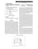
There are two attachments created for this idea that once added to the
engine fixed the problem noted above. The first is an extension of the
crankcase breather tube and the second is an extension of the oil filler
with a breather cap attached at the top. By extending the crankcase
breather tube up and over the engine to point towards the ground on the
other side of the engine, gravity kept the oil from blowing up and out
the tube while emissions still exited the tube from the crankcase. The
extension of the breather tube still allows the pressure built up in the
crankcase to release as originally intended by the manufacturer while
using gravity to keep the oil in the crankcase. Then an extension was
added to the oil filler with a breather cap on it. This oil filler
extension allows for addition pressure release from the crankcase while
also using gravity to keep the engine oil from escaping through the oil
filler. Since this invention was added to the vehicle, there has been no
oil blow out and/or leakage, and normal oil usage during continues
vehicle usage. From 2 Nov. 2013 to 20 Feb. 2014 we have added an
additional 22,000 miles to the vehicle while maintaining normal vehicle
operation with no more major mechanical issues.
Closing
Since the creation of this apparatus, we have temporarily saved the costs
of a new engine costing approximately $21,000 while maintaining an
operational vehicle capable of all originally intended tasks and
maneuvers. This apparatus will work on most diesel engines with this type
of mechanical problem as a, (currently Undetermined amount of time)
temporary solution in avoiding purchasing a new engine. Thus far we have
observed nearly five months of no oil blow out, normal oil usage, and a
fully operation vehicle that would have been otherwise inoperational and
grounded in place.Claims:
1. This is an apparatus that by adding to a diesel engine, stops the
engine oil blow out in many diesel engines. It is made of copper and
rubber piping that extends from original engine parts that worked
insufficiently due to mechanical issues that arouse in the engine. Due to
ingenuity and observation, I created this apparatus in order to use the
force of gravity to keep oil in the engine while allowing pressure to
exhaust from the engine. As an issue arose from the engine, with no
identifiable solution from the manufacturer, I invented this apparatus.
This apparatus was invented on 2 Nov. 2013 in order to solve the problem
of oil blow out in a Caterpillar engine owned by the inventor. The
invention has worked better than expected for the last six months and
continues to be a great solution to the oil loss problem in the engine.
Limitations This apparatus will only work on diesel engines with similar
setups such as the Caterpillar engine I used this apparatus on. The
copper piping used can sustain high heat as it exhausts from the engine
creating much longer lifespan of the crankcase breather tube and
extension. Thus far the apparatus I created has worked to alleviate oil
blowout and is expected to work as long as the engine itself.Description:
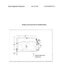
DRAWING LEGEND
Oil Blow out Prevention Kit for Caterpillar Engines
[0001] This legend is set up in an organized number format. Each number on the drawing matches to a number on this legend and beside it follows a description of that part of the drawing.
[0002] 1. Is a 210 Caterpillar C7 ACERT Engine (in our case), but can resemble many diesel engines that can be the base for this apparatus in functionality.
[0003] 2. Oil Filler, like all engines, the oil filler is where oil is added to the engine for lubricating purposes. The oil filler is usually made of a 11/2'' diameter steel pipe and ranges from six to 36 inches long. This is an original engine part, and not a part of the invention or apparatus to be patented. This is instead a basic engine part we added to in part of a solution and the invention.
[0004] 3. Oil Filler extender; a part of our invention that connects to the engine manufacturer's oil filler. This is part of the invention and is made of 11/2'' in diameter galvanized aluminum pipe and is 18'' long.
[0005] 4. Oil Filler Cap with venting holes on bottom side for breathing is 21/2'' wide×11/2'' high/it is a Mr. Gasket Performance Breather Cap (bought at AutoZone, Part number: 2068). This is a part of the solution and is needed to make the invented apparatus to work, but is not a part of the invention. This part is on most automotive parts dealer's shelves and can be substituted for other parts that cap off exhaust piping while allowing it to vent out and relieve pressure.
[0006] 5. Crankcase Breather tube. This is another basic and original engine part from the manufacturer and is 26'' long and made of a 11/2''-in diameter rubber tubing. The tube itself is manufactured to hang vertically where the pressure of the crankcase can relieve pressure straight down to the ground. In part for a solution to keep engine oil from leaking out the downward pointing rubber tubing, we turned it up and connected an extension to it.
[0007] 6. Breather tube extender, made to connect to the breather tubing in order to use gravity to keep the engine from leaking. It is made of a 1'' in diameter copper piping that can stand high heat exiting the crankcase through the breather tube. The breather tube extension is 83'' long and can vary in length from engine to engine, depending on the size of the engine. The purpose of the copper piping is to round the top of the engine to allow pressure from the crankcase to be relieved while gravity keeps the engine oil itself in the crankcase.
[0008] 7. Is a 11/4'' in diameter rubber tube that is 24'' long and is attached to breather tube extender. This part extends the crankcase breather to the ground on the opposite side of the engine compared to the crankcase breather and original manufacturer set up. It also is pointed towards the ground as intended by the manufacturer and original crankcase breather tube.
[0009] 8. Hose clamp/tightening ring clamp for connecting copper breathing pipe (invention part) and rubber tubing (original part) on the driver's side of the engine.
[0010] 9. Hose clamp/tightening ring clamp for connecting cooper breathing pipe (invention part) and rubber tubing (invention part) on the passenger side of the engine.
User Contributions:
Comment about this patent or add new information about this topic:
Images included with this patent application:
 |  |
 |
| Similar patent applications: | |
| Date | Title |
|---|---|
| 2015-12-03 | Intake valve closure control for dual-fuel engines |
| 2016-03-24 | Ignition unit for an internal combustion engine |
| 2015-12-03 | Fuel apportionment for multi fuel engine system |
| 2016-03-31 | Continuous variable valve duration apparatus and engine provided with the same |
| 2015-12-17 | Oil cooling system for supercharged engine |
| New patent applications in this class: | |
| Date | Title |
|---|---|
| 2016-06-02 | Evacuator system for supplying high suction vacuum or high suction flow rate |
| 2015-11-26 | Separation device for an aerosol stream |
| 2015-11-26 | Oil separator |
| 2015-05-21 | Systems and methods for closed crankcase ventilation and air filtration |
| 2015-04-30 | Engine and straddle-type vehicle including the same |
| Top Inventors for class "Internal-combustion engines" | |
| Rank | Inventor's name |
|---|---|
| 1 | Ross Dykstra Pursifull |
| 2 | Gopichandra Surnilla |
| 3 | Joseph Norman Ulrey |
| 4 | Thomas G. Leone |
| 5 | Chris Paul Glugla |