Patent application title: APPARATUS FOR REDUCING WATER-BLOOM AND REMOVING FLOATING MATTERS USING INFRARED RAY SENSOR AND GPS
Inventors:
Hyung Eui Hong (Gyeonggi-Do, KR)
IPC8 Class: AE02B1510FI
USPC Class:
21017005
Class name: Structural installation geographic floating means
Publication date: 2015-10-15
Patent application number: 20150292174
Abstract:
Provided is an apparatus for reducing water-bloom and removing floating
matters using an infrared ray sensor and a GPS, wherein driving force can
be supplied through a solar photovoltaic power module, and there are
provided a motored propelling unit, for example, a propeller, and an
infrared ray sensor for detecting the presence of a predetermined thing,
so the apparatus can automatically move on the surface of water, and the
generation of water-bloom, for example, algae, may be inhibited using
ultrasonic waves, and in case where electric power supply is impossible
because the lack of quantity of solar radiation, the apparatus may
automatically return to the dock using the GPS device, thus being
electrically charged.Claims:
1. An apparatus for reducing water-bloom and removing floating matters,
comprising: wherein a plurality of buoys each having a solar photovoltaic
power generation module are grouped and fixed to each other, thus
floating on the surface of water, a blade which is provided at a front
side of the apparatus for reducing water-bloom and removing floating
matters, so as to filter the floating matters or water-bloom on the
surface of water; a motored propelling unit which is provided at a rear
side of the apparatus for reducing water-bloom and removing floating
matters, so as to generate propelling force with the aid of electric
power generated through the solar photovoltaic power generation module;
and one or a plurality of detection means which is provided at a
predetermined portion of the apparatus for reducing water-bloom and
removing floating matters, so as to detect the presence of a
predetermined obstacle under the water or on the surface of water for the
sake of a direction change during the operations on the surface of water.
2. The apparatus of claim 1, further comprising: one or a plurality of ultrasonic wave generators which is provided at a predetermined portion of the apparatus for reducing water-bloom and removing floating matters, so as to remove water-bloom by emitting ultrasonic waves into water.
3. The apparatus of claim 1, further comprising: a GPS control unit and a GPS receiving unit which are provided at a predetermined portion of the apparatus for reducing water-bloom and removing floating matters, so as to trace the position of the apparatus for reducing water-bloom and removing floating matters or move the apparatus for reducing water-bloom and removing floating matters to a predetermined position.
4. The apparatus of claim 3, wherein a charging terminal is provided at one side of the apparatus for reducing water-bloom and removing floating matters, so as to receive external electric power, and the apparatus for reducing water-bloom and removing floating matters is able to return to a charging dock with the aid of the GPS receiving unit and the GPS control unit, and the charging terminal is connected to a charging unit of the charging dock, thus being electrically charged.
5. The apparatus of claim 1, wherein at a wall surface of each of the buoy, there is provided a rail groove the cross section of which is formed in a `` shape, and the bottom of which is closed, and the top of which is open, and there is further provided a connector the cross section of which is formed in a ``-shape so that the connector is inserted downward from the open top of the rail groove and separates upward, and when the outer walls of each buoy face each other, the connectors are concurrently inserted into the rail grooves in a state where each rail groove faces each other, thus fixedly interconnecting the neighboring buoys.
6. The apparatus of claim 5, wherein the blade or the motored propelling unit is fixed at one side of the connector, respectively, and the other side of the connector slides and is inserted in the rail groove of the buoy, so the blade or the motored propelling unit is fixed at the buoy, respectively.
Description:
CROSS REFERENCE
[0001] This application claims foreign priority under Paris Convention to Korean Patent Application No. 10-2014-0041401, filed 7 Apr. 2014, with the Korean Intellectual Property Office.
BACKGROUND
[0002] The present invention relates to an apparatus for reducing water-bloom and removing floating matters using an infrared ray sensor and a GPS, and in particular to an apparatus for reducing water-bloom and removing floating matters using an infrared ray sensor and a GPS, wherein a blade and a propeller are installed at a buoy equipped with a solar photovoltaic power generation module, and an automatic sailing may be obtained using the infrared ray sensor and the GPS, while removing algae, impurities and various floating matters on the surface of water.
[0003] A dam in general is constructed for the sake of hydroelectric power generation or agriculture water supply or in order to prevent any overflow of a stream or a river due to flood. A variety of floating matters, for example, leaves, wastes, etc. at a reservoir, a lake or the like made by the dam may contaminate the quality of water and the quality of water may be contaminated because of water-bloom in summer or fishes may die from such contamination, for which social cost increases.
[0004] In order to improve the above-mentioned problems, a predetermined method or apparatus has been suggested, which is designed to resolve anaerobic states or inhibit the generation of algae, for example, water-bloom in such a way to generate superfine air bubbles using a micro bubble generator and spurt into water; however lots of cost and time is entailed because it is almost impossible to spurt superfine air bubbles into the water of the whole area of lake which reserves a lot of water, which thus is impractical. There is a limit in the way that such a bubble generator can't remove floating matters, for example, leaves, wastes, etc.
[0005] As a prior art on the apparatus for removing matters (bubbles, scum, etc.) floating on the surface of water, there is the Korean Utility Model Registration No. 0445430 (Patent Document 1) entitled a sunlight-based apparatus for automatically removing floating matters, wherein a frame is installed on the ground, and an operation panel is installed at a backside of the frame, and a solar cell is installed on the top of the operation panel, and a screw jack, a driving unit, is fixed at the top of a front side of the frame, and a connection pipe and a collection hopper are coaxially connected to a screw nut which moves up and down based on the rotation of the screw of the screw jack, and operate upward and downward together, and a sensor bracket fixed at the connection hopper, a water level detection sensor engaged to the sensor bracket and a water level problem detection sensor all serve to detect the level of water, thus adjusting the position of the collection hopper, and a piston pipe is attached to the bottom of a cone of the collection hopper 22, and a piston housing is configured to perform a guide function in order for the ascending and descending operations to be performed reliable without any swaying.
[0006] Since the apparatus of the patent document 1 is driven by sunshine, it is advantageous in that power consumption-related operation cost is not necessary, but it is constructed in a structure wherein water is used to guide water into the apparatus, so further cost for retreatment is entailed. In addition, since the apparatus is fixed at a predetermined portion when in use, it is hard to effectively remove the matters randomly floating over the whole surface of a reservoir or a lake.
SUMMARY OF THE INVENTION
[0007] Accordingly, it is an object of the present invention to provide an apparatus for reducing water-bloom and removing floating matters using an infrared ray sensor and a GPS, wherein electric power is supplied with the aid of a solar photovoltaic power generation module, and there are provided a motored propelling unit, for example, a propeller and an infrared ray sensor or recognizing the presence of a predetermined matter, so the apparatus is automatically operable on the surface of water, and the generation of algae, for example, water-bloom, etc. may be inhibited, and in case where electric power supply is hard due to the lack of quantity of solar radiation, the apparatus may automatically return to a dock using a GPS device and may be electrically charged.
[0008] To achieve the above object, there is provided an apparatus for reducing water-bloom and removing floating matters, which wherein a plurality of buoys each having a solar photovoltaic power generation module are grouped and fixed to each other, thus floating on the surface of water, may include a blade which is provided at a front side of the apparatus for reducing water-bloom and removing floating matters, so as to filter the floating matters or water-bloom on the surface of water; a motored propelling unit which is provided at a rear side of the apparatus for reducing water-bloom and removing floating matters, so as to generate propelling force with the aid of electric power generated through the solar photovoltaic power generation module; and one or a plurality of detection means which is provided at a predetermined portion of the apparatus for reducing water-bloom and removing floating matters, so as to detect the presence of a predetermined obstacle under the water or on the surface of water for the sake of a direction change during the operations on the surface of water.
[0009] As an exemplary embodiment of the present invention, there is further provided one or a plurality of ultrasonic wave generators which is provided at a predetermined portion of the apparatus for reducing water-bloom and removing floating matters, so as to remove water-bloom by emitting ultrasonic waves into water.
[0010] In the present invention, there may be further provided a GPS control unit and a GPS receiving unit which are provided at a predetermined portion of the apparatus for reducing water-bloom and removing floating matters, so as to trace the position of the apparatus for reducing water-bloom and removing floating matters or move the apparatus for reducing water-bloom and removing floating matters to a predetermined position.
[0011] In the present invention, a charging terminal is provided at one side of the apparatus for reducing water-bloom and removing floating matters, so as to receive external electric power, and the apparatus for reducing water-bloom and removing floating matters is able to return to a charging dock with the aid of the GPS receiving unit and the GPS control unit, and the charging terminal is connected to a charging unit of the charging dock, thus being electrically charged.
[0012] According to the present invention, most of the electric power which may be used to drive the apparatus comes from the solar photovoltaic power generation module, thus minimizing the operation cost, and since the apparatus automatically sails everywhere on the surface of water, a floating matter removal and a water-bloom reduction operation are very effective on the whole surfaces of water even at a lack or a reservoir that holds a lot of water.
[0013] In addition, since it is possible to detect the operation state of the apparatus for reducing water-bloom and removing floating matters, using the GPS, monitoring the apparatus is easy, and in case where electric power lacks, the apparatus may automatically return to the dock where there is provided an electric power charger and may be charged and may start working again, thus minimizing the number of workers.
BRIEF DESCRIPTION OF THE DRAWINGS
[0014] The present invention will become better understood with reference to the accompanying drawings which are given only by way of illustration and thus are not limitative of the present invention, wherein;
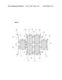
[0015] FIG. 1 is a plane view illustrating an apparatus for reducing water-bloom and removing floating matters according to an exemplary embodiment of the present invention;
[0016] FIG. 2 is a side view illustrating an apparatus for reducing water-bloom and removing floating matters according to an exemplary embodiment of the present invention;
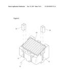
[0017] FIG. 3 is a plane view illustrating a charging state of an apparatus for reducing water-bloom and removing floating matters according to an exemplary embodiment of the present invention;
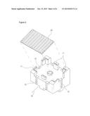
[0018] FIG. 4 is a separated perspective view illustrating a buoy and a solar photovoltaic power generation module which belong to an apparatus for reducing water-bloom and removing floating matters according to an exemplary embodiment of the present invention;
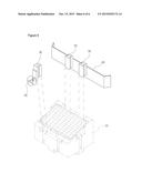
[0019] FIG. 5 is a view for describing an assembled configuration of a buoy which belongs to an apparatus for reducing water-bloom and removing floating matters according to an exemplary embodiment of the present invention; and
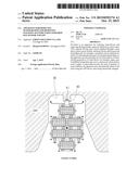
[0020] FIG. 6 is a view for describing an assembled configuration of other components which belong to an apparatus for reducing water-bloom and removing floating matters according to an exemplary embodiment of the present invention.
DETAILED DESCRIPTION OF THE INVENTION
[0021] The exemplary embodiment of the present invention will be described with reference to the accompanying drawings. The embodiments disclosed below are provided so as to help the understanding of the present invention, not intending to limit the scope of the present invention. The descriptions on the technology that a person having ordinary skill in the art may easily understand may be omitted.
[0022] FIG. 1 is a plane view illustrating an apparatus for reducing water-bloom and removing floating matters according to an exemplary embodiment of the present invention, FIG. 2 is a side view illustrating an apparatus for reducing water-bloom and removing floating matters according to an exemplary embodiment of the present invention, and FIG. 3 is a plane view illustrating a charging state of an apparatus for reducing water-bloom and removing floating matters according to an exemplary embodiment of the present invention.
[0023] As illustrated in FIGS. 1 and 2, an apparatus for reducing water-bloom and removing floating matters using an infrared ray sensor and a GPS according to the present invention is characterized in that a plurality of buoys 10 each having a solar photovoltaic power generation module 20 are grouped and fixed each other and float on the surface of water. Here, the buoys 10 may be constituted by connecting six buoys 10, and the number of the buoys 10 may increase or decrease, if necessary, and the buoys 10 may be made of a predetermined material or in a predetermined shape as long as the buoys 10 can float on the surface of water.
[0024] The solar photovoltaic power generation modules 20 are configured to generate electric power with the aid of sunshine and are commercially available in a variety of fields, so the descriptions thereof will be omitted.
[0025] In front of the apparatus for reducing water-bloom and removing floating matters of the present invention, a mesh type or bar type blade 4 is installed so as to remove the floating matters on the surface of water or water-bloom. It is preferred that both ends of the blade 4 may be bent at a predetermined angle in a forward direction so as to prevent the floating matters filtered by the blade 40 from escaping in lateral directions.
[0026] Behind the apparatus for reducing water-bloom and removing floating matters of the present invention, a motored propelling unit 50, for example, a propeller, is provided so as to move, on the surface of water, the apparatus for reducing water-bloom and removing floating matters. The motored propelling unit 50 generates a propelling force as it rotates with the aid of electric power which is generated y the solar photovoltaic power generation module 20.
[0027] Meanwhile, a detection unit 60, for example, an infrared ray sensor, may be provided in at least one portion of or at a plurality of near portions of the apparatus for reducing water-bloom and removing floating matters so as to prevent a collision of the apparatus for reducing water-bloom and removing floating matters, with respect to a predetermined obstacle, rock, land, etc. when the apparatus for reducing water-bloom and removing floating matters sails unmanned, with the aid of the motored propelling unit 50. When the detection unit 60 detects a predetermined obstacle, a control unit 14 provided inside or outside the buoy 10 adjusts the motored propelling unit 50, thus changing the moving direction of the apparatus for reducing water-bloom and removing floating matters of the present invention.
[0028] The detection scope of the detection sensor 60 ranges long enough to detect meters or tens of meters under the water and/or on the surface of water, thus detecting in advance all obstacles such as rocks, walls, etc.
[0029] Meanwhile, the apparatus for reducing water-bloom and removing floating matters may include an ultrasonic wave generator 70 which is able to inhibit the growth of water-bloom and remove the water-bloom by emitting ultrasonic waves into the water while moving on the surface of water. The ultrasonic wave generator 70 may be installed at a portion of or multiple portions of the apparatus for reducing water-bloom and removing floating matters.
[0030] The ultrasonic waves emitted from the ultrasonic wave generator 70 destroy the cell membranes of the water-bloom in order to make the water-bloom not float onto the surface of water, but submerge under the water, thus removing the water-bloom.
[0031] In addition, the apparatus for reducing water-bloom and removing floating matters of the present invention may include a GPS control unit 15 and a GPS receiving unit 16 at a predetermined portion of the apparatus for reducing water-bloom and removing floating matters so as to track the position of the apparatus for reducing water-bloom and removing floating matters or so as to control the apparatus for reducing water-bloom and removing floating matters to move to a predetermined portion of the reservoir or the lake.
[0032] Here, the GPS (Global Positioning System) is a common system which is able to recognize the position of a predetermined thing with the aid of a satellite. In case where the apparatus for reducing water-bloom and removing floating matters includes the GPS control unit 15 and the GPS receiving unit 16, it is possible to detect in real time the position of the apparatus for reducing water-bloom and removing floating matters, and when an operator inputs a coordinate corresponding a predetermined position and transmits the coordinate, the apparatus for reducing water-bloom and removing floating matters can automatically move to the predetermined position.
[0033] Meanwhile, in case where the operation of the apparatus for reducing water-bloom and removing floating matters is impossible because of the low electric power generation of the solar photovoltaic power generation module 20 or the lack of the electric power charged in the charging unit 13, a charging terminal 80 may be provided at one side of the apparatus for reducing water-bloom and removing floating matters so as to receive external electric power.
[0034] As illustrated in FIG. 3, the charging terminal 80 may be electrically connected to the charging unit 91 of the charging dock 90 provided at a predetermined portion of a reservoir or a lack for the sake of charging the apparatus for reducing water-bloom and removing floating matters, thus receiving electric power. At this time, when the GPS receiving unit 16 and the GPS control unit 15 are installed at the apparatus for reducing water-bloom and removing floating matters, as described above, it is possible to move the apparatus for reducing water-bloom and removing floating matters to a position where the charging dock 90 is installed.
[0035] For example, if the charged voltage of the charging unit 13 is detected lower than a predetermined level in the middle of the operation of the apparatus for reducing water-bloom and removing floating matters, the control unit 14 may move the apparatus for reducing water-bloom and removing floating matters to a previously inputted coordinate position, namely, to the position where the charging dock 90 is installed. In addition, the charging terminal 80 and the charging unit 91 may be automatically connected to each other with the aid of the detection unit 60 and the direction changing function of the propelling unit 50.
[0036] FIG. 4 is a separated perspective view illustrating a buoy and a solar photovoltaic power generation module which belong to an apparatus for reducing water-bloom and removing floating matters according to an exemplary embodiment of the present invention, FIG. 5 is a view for describing an assembled configuration of a buoy which belongs to an apparatus for reducing water-bloom and removing floating matters according to an exemplary embodiment of the present invention, and FIG. 6 is a view for describing an assembled configuration of other components which belong to an apparatus for reducing water-bloom and removing floating matters according to an exemplary embodiment of the present invention.
[0037] Referring to FIGS. 4 and 5, the upper surface of the buoy 10 may be obliquely formed, and a support end portion 11 is formed at multiple portions of the edge of the top of the buoy 10 so as to fixedly mount the solar photovoltaic power generation module 20.
[0038] In addition, at a wall surface of each of the buoys 10, there is provided a rail groove 12 the cross section of which is formed in a "" shape, the bottom of which is closed, and the top of which is open. In this case, when the outer walls of the neighboring buoys 10 face each other, and the corresponding rail grooves 12 face each other, the cross section looks like a "" shape.
[0039] Therefore, a connector 30 is provided so as to interconnect the neighboring buoys 10, and the connector 30 has a cross section which looks like a "" shape and may slide and be inserted from the open top of the rail groove 12 into the lower side and may be separated as the connector 30 slides upward in the inserted state.
[0040] In this way, the connectors may concurrently slide and be inserted into the rail grooves 12 of the neighboring buoys 10, thus fixing the neighboring buoys 10.
[0041] Referring to FIG. 6, according to an example for reliably fixing the components such as the blade 40, the motored propelling unit 50, etc. at a predetermined portion of the buoy 10, the blade 40 or the motored propelling unit 50 may be fixed at one side of the connector 30, and the other side of the connector 30 may be inserted in the rail groove 12 of the buoy 10.
[0042] In this case, the blade 40 or the motored propelling unit 50 may be detachably installed through the connector 30.
[0043] As the present invention may be embodied in several forms without departing from the spirit or essential characteristics thereof, it should also be understood that the above-described examples are not limited by any of the details of the foregoing description, unless otherwise specified, but rather should be construed broadly within its spirit and scope as defined in the appended claims, and therefore all changes and modifications that fall within the meets and bounds of the claims, or equivalences of such meets and bounds are therefore intended to be embraced by the appended claims.
User Contributions:
Comment about this patent or add new information about this topic:
| People who visited this patent also read: | |
| Patent application number | Title |
|---|---|
| 20220037526 | SEMICONDUCTOR DEVICE |
| 20220037525 | HIGH VOLTAGE SEMICONDUCTOR DEVICE HAVING BOOTSTRAP DIODE |
| 20220037524 | TRANSISTOR SEMICONDUCTOR DIE WITH INCREASED ACTIVE AREA |
| 20220037523 | SEMICONDUCTOR DEVICE AND METHOD FOR MANUFACTURING SAME |
| 20220037522 | TRENCH MOSFET AND METHOD FOR MANUFACTURING THE SAME |
Images included with this patent application:
 |  |
 |  |
 |  |
 |
| Similar patent applications: | |
| Date | Title |
|---|---|
| 2016-04-07 | Apparatus for separating materials from an influent stream |
| 2015-10-29 | Apparatus for removing protein-bound toxins from blood plasma |
| 2016-04-07 | Fluid filtration apparatuses and fluid filtration systems related thereto |
| 2015-12-31 | Apparatus for blood purification by extracorporeal circulation |
| 2016-01-14 | Fuel water separator having filter and sensor |
| New patent applications in this class: | |
| Date | Title |
|---|---|
| 2016-06-30 | A device for removal of oil under ice |
| 2016-06-30 | Floating filtration apparatus transfers seawater without harm to marine life, |
| 2015-02-05 | Oil collecting apparatus |
| 2015-01-29 | Oil recovery system |
| 2014-12-04 | Purification apparatus, system, and method |
| Top Inventors for class "Liquid purification or separation" | |
| Rank | Inventor's name |
|---|---|
| 1 | Robert W. Childers |
| 2 | Joseph A. King |
| 3 | Martin T. Gerber |
| 4 | John R. Hacker |
| 5 | Rodolfo Roger |