Patent application title: MEMRISTOR LINEAR MODELING METHOD FOR SWITCHED RELUCTANCE MOTOR
Inventors:
Hao Chen (Jiangsu, CN)
Yan Liang (Jiangsu, CN)
Dongsheng Yu (Jiangsu, CN)
IPC8 Class: AG06F1711FI
USPC Class:
Class name:
Publication date: 2015-08-06
Patent application number: 20150220484
Abstract:
A memristor linear modeling method for a switched reluctance motor. A
non-inverting operational amplifier circuit and an inverting operational
amplifier circuit are employed to construct a switched reluctance motor
linear phase inductance characteristic element.Claims:
1. A memristor-based linear modeling method for switched reluctance
motors, the method comprising: connecting the input of a non-inverting
operational amplifier circuit with the input of an inverting operational
amplifier circuit as the input terminal θ of a linear phase
inductance characteristic element of a switched reluctance motor, adding
the output of the non-inverting operational amplifier circuit with the
output of the inverting operational amplifier circuit via a non-inverting
additional operational circuit as the output terminal L(θ) of the
linear phase inductance characteristic element of the switched reluctance
motor, to construct a linear phase inductance characteristic element W
for the switched reluctance motor; taking the positional angle θ of
the rotor of the switched reluctance motor as the input of the linear
phase inductance characteristic element of the switched reluctance motor,
and obtaining a memorized conductance value L(θ) comprising the
phase inductance of the switched reluctance motor from the output of the
constructed linear phase inductance characteristic element of the
switched reluctance motor; treating the angular velocity ω(t) of
the switched reluctance motor via a scaling operational circuit OA1
and an integrator circuit OA2, to obtain the positional angle
θ of the rotor of the switched reluctance motor; connecting a
current reversing circuit OA3 between an input terminal 1 of a
multiplier U1 and an output terminal 7 of the multiplier U1; connecting
the output terminal L(θ) of the linear phase inductance
characteristic element of the switched reluctance motor to an input
terminal 3 of the multiplier U1, and connecting the terminal g of input
current i(t) and input voltage V(t) to the input terminal 1 of the
multiplier U1; the input current i(t), the input voltage V(t) and the
phase inductance L(θ) meeting the following relational expression:
i(t)=[αL(θ)]V(t), where, α is a constant.Description:
CROSS-REFERENCE TO RELATED APPLICATIONS
[0001] This application is a national phase entry under 35 U.S.C. §371 of International Patent Application PCT/CN2013/070929, filed Jan. 24, 2013, designating the United States of America and published as International Patent Publication WO 2014/063452 A1 on May 1, 2014, which claims the benefit under Article 8 of the Patent Cooperation Treaty to Chinese Patent Application Serial No. 201210403809.X 2012, filed Oct. 22, 2012.
TECHNICAL FIELD
[0002] This disclosure relates to electronic generally and more particularly to a memristor-based modeling method for switched reluctance motors, which is applicable to switched reluctance motors with any number of phases.
BACKGROUND
[0003] The modeling of a switched reluctance motor has direct influence on the optimal design, static and dynamic performance analysis, and evaluation of control strategy, etc., of the motor. It is difficult to apply the performance analysis and modeling methods for conventional motors to the modeling of switched reluctance motors, owing to the nonlinear electromagnetic property and close coupling among multiple variables in switched reluctance motors. A linear model of switched reluctance motor highlights the physical nature of internal electromagnetic relation in switched reluctance motors and sets a basis for the design and analysis of switched reluctance motors. The linear model of switched reluctance motor neglects nonlinear factors such as magnetic field saturation, eddy current, magnetic hysteresis, and inter-phase mutual inductance, etc., so that the inductance of each phase is only related with the positional angle of the rotor and independent of the phase current magnitude. Such simplification brings great convenience for analysis of the operating characteristics of switched reluctance motors. With that model, it is easy to obtain an analytical expression of phase current vs. electromagnetic torque of switched reluctance motors, and thereby, the rule of influence of status parameters such as turn-on angle, turn-off angle, and given voltage on the characteristics of motor can be analyzed conveniently, and the performance of control scheme for a switched reluctance motor can be assessed, so as to provide valuable reference for controller design and debugging.
[0004] A memristor is a passive two-terminal element and has unique memory function, and its resistance can be changed by controlling the voltage across it or the current flowing through it. Thanks to the memory function, memristors have a high application potential in nonvolatile memory unit, artificial neural network, and image processing fields. A mathematical model has to be set up to carry out theoretical analysis for switched reluctance motors. A key in the modeling is that the model must be able to reflect the inductance (or magnetic linkage) characteristics of switched reluctance motors. The memristor theory and method can be used to try to set up a model of switched reluctance motors, in which the phase inductance of switched reluctance motor is controlled by the positional angle of the rotor and the resistance change trend can be memorized.
DISCLOSURE
[0005] To solve the problems in the prior art, the disclosure described herein provides a memristor-based linear modeling method for switched reluctance motors, which is simple and can improve static and dynamic system properties, and implement real-time simulation and real-time control of the switched reluctance motor system.
[0006] The memristor-based linear modeling method for switched reluctance motors comprises:
[0007] a) connecting the input of a non-inverting operational amplifier circuit with the input of an inverting operational amplifier circuit as the input terminal θ of a linear phase inductance characteristic element of a switched reluctance motor, adding the output of the non-inverting operational amplifier circuit with the output of the inverting operational amplifier circuit via a non-inverting additional operational circuit as the output terminal L(θ) of the linear phase inductance characteristic element of the switched reluctance motor, to construct a linear phase inductance characteristic element W for the switched reluctance motor;
[0008] taking the positional angle θ of the rotor of the switched reluctance motor as the input of the linear phase inductance characteristic element of the switched reluctance motor, and obtaining a memorized conductance value L(θ) (i.e., phase inductance of the switched reluctance motor) from the output of the constructed linear phase inductance characteristic element of the switched reluctance motor;
[0009] b) treating the angular velocity ω(t) of the switched reluctance motor via a scaling operational circuit OA1 and an integrator circuit OA2 to obtain the positional angle θ of the rotor of the switched reluctance motor;
[0010] c) connecting a current reversing circuit OA3 between an input terminal 1 of a multiplier U1 and an output terminal 7 of the multiplier U1;
[0011] d) connecting the output terminal L(θ) of the linear phase inductance characteristic element of the switched reluctance motor to an input terminal 3 of the multiplier U1, and connecting the terminal g of input current i(t) and input voltage V(t) to the input terminal 1 of the multiplier U1;
[0012] the input current i(t), the input voltage V(t) and the phase inductance L(θ) meeting the following relational expression:
[0013] i(t)=[αL(θ)]V(t), where, a is a constant; in this way, a memristor-based linear model of switched reluctance motor is obtained.
[0014] Beneficial effects: with the method provided in this disclosure, based on the electromagnetic property of phase windings of a switched reluctance motor and an ideal linear inductance model, a memristor-based linear model of switched reluctance motor is set up, in which the phase inductance is independent of the phase current magnitude but is controlled only by the positional angle of the rotor, and the phase inductance can memorize the resistance change trend. The phase circuit model, which is a memristor-based model and reflects the phase inductance characteristics of a switched reluctance motor, in which the positional signal of rotor and phase inductance terminal voltage are considered as input variables of a three-terminal memristor, and the resistance of the memristor varies following the position change of the rotor. That method sets a basis for constructing a complete switched reluctance motor system model, and is helpful for implementing nonlinear analytical modeling and real-time control of switched reluctance motors. Application of a memristor to the switched reluctance motor model can facilitate integration and optimization of the model, is helpful for optimizing the design and control parameters of switched reluctance motors and effectively improving static and dynamic system properties, and can implement real-time simulation and real-time control of switched reluctance motor systems. Therefore, the method has broad application prospects.
BRIEF DESCRIPTION OF THE DRAWING
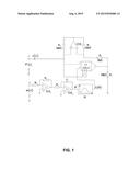
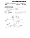
[0015] FIG. 1 is a schematic diagram of the memristor-based model of a phase circuit of a switched reluctance motor provided in the herein-described disclosure.
DETAILED DESCRIPTION
[0016] Hereunder, this disclosure will be further detailed in an embodiment, with reference to the accompanying drawing.
[0017] As shown in FIG. 1, the memristor-based linear modeling method for switched reluctance motors in the herein-described disclosure comprises:
[0018] a) connecting the input of a non-inverting operational amplifier circuit with the input of an inverting operational amplifier circuit as the input terminal θ of a linear phase inductance characteristic element of a switched reluctance motor, adding the output of the non-inverting operational amplifier circuit with the output of the inverting operational amplifier circuit via a non-inverting additional operational circuit as the output terminal L(θ) of the linear phase inductance characteristic element of the switched reluctance motor, to construct a linear phase inductance characteristic element W for the switched reluctance motor;
[0019] taking the positional angle θ of the rotor of the switched reluctance motor as the input of the linear phase inductance characteristic element W of the switched reluctance motor, and obtaining a memorized conductance value L(θ) (i.e., phase inductance of the switched reluctance motor) from the output of the constructed linear phase inductance characteristic element W of the switched reluctance motor;
[0020] b) treating the angular velocity ω(t) of the switched reluctance motor via a scaling operational circuit OA1 and an integrator circuit OA2 at terminal d, to obtain the positional angle θ of the rotor of the switched reluctance motor, wherein, an operational amplifier Y1 in OA1 works with an external resistor R1 and an external resistor R2 to provide proportional amplification function, and an operational amplifier Y2 in OA2 works with an external resistor R3 and an external capacitor C1 to provide integration function;
[0021] c) connecting a current reversing circuit OA3 between an input terminal 1 of a multiplier U1-AD633 and an output terminal 7 of the multiplier U1-AD633, wherein, the external resistors R4 and R5 have the same resistance, i.e., R4=R5=10 kΩ, the external resistor R6=1 kΩ, and the external resistor R7=10 kΩ; input terminals 2 and 4 of the multiplier U1-AD633 are grounded, and an input terminal 6 of the multiplier U1-AD633 is also connected to the terminal g;
[0022] d) connecting the output terminal L(θ) of the linear phase inductance characteristic element W of the switched reluctance motor to an input terminal 3 of the multiplier U1, and the input voltage V(t) at the terminal g is connected to the input terminal 1 of the multiplier U1-AD633;
[0023] e) input current i(t) at the terminal g, input voltage V(t) at the terminal g and phase inductance L(θ) meeting the following relational expression:
[0023] α = 1 10 R 6 = 1 1000 ##EQU00001##
[0024] i(t)=[αL(θ)]V(t), where, α is a constant;
[0025] in that way, a memristor-based linear model of switched reluctance motor is obtained.
User Contributions:
Comment about this patent or add new information about this topic:
| People who visited this patent also read: | |
| Patent application number | Title |
|---|---|
| 20170174166 | HORN CIRCUIT |
| 20170174165 | CLAMPING ARRANGEMENT FOR SECURING AN AIRBAG TO AN INFLATOR |
| 20170174164 | AIR BAG SENSOR ASSEMBLY |
| 20170174163 | OCCUPANT PROTECTION METHOD AND OCCUPANT PROTECTION DEVICE OF A VEHICLE |
| 20170174162 | IMPACT SENSOR ASSEMBLY FOR ACTIVE HOOD SYSTEM |
Images included with this patent application:
 |  |
| New patent applications in this class: | |
| Date | Title |
|---|---|
| 2022-09-08 | Shrub rose plant named 'vlr003' |
| 2022-08-25 | Cherry tree named 'v84031' |
| 2022-08-25 | Miniature rose plant named 'poulty026' |
| 2022-08-25 | Information processing system and information processing method |
| 2022-08-25 | Data reassembly method and apparatus |
| New patent applications from these inventors: | |
| Date | Title |
|---|---|
| 2021-12-23 | Pharmaceutical composition comprising parp inhibitors |
| 2016-03-31 | Fault diagnosis method for freewheeling diodes of dual-switch power converter of switched reluctance motor |
| 2015-11-19 | Node energy diagnosis method for fault of switched reluctance motor double-switch power converter |