Patent application title: PORTABLE DWELLING ASSEMBLY
Inventors:
Terry Bunce (Carlisle, IA, US)
IPC8 Class: AE04B1343FI
USPC Class:
Class name:
Publication date: 2015-08-06
Patent application number: 20150218792
Abstract:
A portable dwelling assembly that has a dome shape and a door assembly.
The dome assembly is provided with a base ring and top ring connected by
a plurality of wall segments. Connected to the exterior of the dome
assembly is a covering with optional flaps to allow for greater
ventilation. Anchoring devices are attached around the exterior of the
dwelling to provide additional stability during adverse weather.Claims:
1. A portable dwelling assembly comprising; a dome assembly having a base
ring and a top ring and a plurality of wall segments therebetween; a door
assembly positioned on the dome assembly; and a covering adhered to an
exterior of the dome assembly.
2. The portable dwelling assembly of claim 1 further comprising anchoring devices positioned on the exterior of the covering.
3. The portable dwelling assembly of claim 1 further comprising a plurality of feet connected to the base ring.
4. The portable dwelling assembly of claim 1 further comprising a plurality of attachment devices connected to an exterior of the covering.
5. The portable dwelling assembly of claim 4 further comprising anchor devices connected to the plurality of attachment devices.
6. The portable dwelling assembly of claim 1 further comprising the covering having an electric conduit connected to a generator.
7. The portable dwelling assembly of claim 1 further comprising reinforcing loops attached to an interior side of the wall segments.
8. The portable dwelling assembly of claim 1 further comprising a hammock positioned between reinforcing loops.
9. The portable dwelling assembly of claim 1 further comprising the top ring having an opening not covered by the covering.
10. The portable dwelling assembly of claim 1 further comprising the base ring having a plurality of base ring segments connected to one another.
11. The portable dwelling assembly of claim 10 further comprising the plurality of base ring segments connected by segment sleeves.
Description:
BACKGROUND OF THE INVENTION
[0001] This invention relates to portable dwellings. More specifically, this invention relates to a dome shaped dwelling to be used as low cost and easy to setup housing.
[0002] Natural disasters have displaced millions. A primary objective of disaster relief is to provide a form of emergency housing to those displaced. Prior to the development of permanent structures low cost and easy to setup dwellings are used to provide immediate protection from the elements.
[0003] Such portable dwellings are old and well known in the art. While these dwellings may be low-cost and easy to setup, they do not adequately address extreme temperatures or severe weather conditions. Thus, a need in the art exists for a dwelling that is low-cost and easy to setup, while providing improved protection from the extreme heat by increasing ventilation, and increased protection from high winds and rain associated with storms.
[0004] Thus it is a principal object of the present invention to provide a portable dwelling that improves ventilation.
[0005] Another object of the invention is to provide a dwelling that is low-cost, easy to setup, transport, and reuse.
[0006] Yet another object of the invention is to provide a dwelling that provides improved protection against the elements.
[0007] These and other objects, features, and advantages will become apparent from the specification and claims.
BRIEF SUMMARY OF THE INVENTION
[0008] A portable dwelling assembly is provided by connecting a plurality of wall segments to a base ring and a top ring. A door assembly is placed between a set of wall segments and a covering is placed on the exterior of the assembly to protect from the elements. In addition, anchoring devices are attached to the covering to add additional weight to the dwelling.
BRIEF DESCRIPTION OF THE DRAWINGS
[0009] FIG. 1 is a perspective view of a portable dwelling assembly;
[0010] FIG. 2 is a perspective view of a portable dwelling assembly;
[0011] FIG. 3 is a perspective view of a portable dwelling assembly; and
[0012] FIG. 4 is a perspective view of a portable dwelling assembly.
DETAILED DESCRIPTION OF THE PREFERRED EMODIMENT
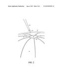
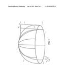
[0013] FIG. 1 shows a portable dwelling assembly 10 that has a dome assembly 11. The dome assembly 10 has a base ring 12 that is generally round in shape and is made of a hollow aluminum alloy, but can be made of any plastic, metal, fiberglass, or any other suitable lightweight material to provide strength and durability. The base ring 12 is preferably twelve feet in diameter, but may be of any size. In one embodiment the base ring 12 is made of a plurality of base ring segments 14 that have a first end 16 and a second end 18. The first end 16 of a base ring segment 14 is connected to the second end 18 of a second ring segment 14 by a segment sleeve 20 that is positioned between the ring segments 14 and receives and frictionally engages the respective ends 14 and 16 within the openings 22 in the sleeve 20. The ring segments 14 may also be connected to one another by welding, bolting, screwing, snap fitting, or any other conventional manner. In one embodiment the sleeve 20 has a foot 24 that extends outwardly and generally perpendicular to the sleeve openings 22 to add stability to the base ring by engaging the ground. Alternatively, the feet 24 are attached directly to the base ring 12. The sleeve may also be permanently attached to the second end 18 of the ring segment 14. In an alternative embodiment the base ring 12 is a continuous body.
[0014] Positioned on the top surface of the base ring 12 are a plurality of openings 26. Preferably the openings 26 are spaced three feet apart along the circumference of the base ring 12, but spacing may be of any length. In one embodiment the openings 26 are located on connection sleeves 28 that extend upwardly from the ring segments 14. Alternatively, the connection sleeves 28 can extend upwardly from the segment sleeves 20.
[0015] Received within the openings 26 is a bottom end 30 of a plurality of wall segments 32. Preferably, the wall segments 32 frictionally engage the openings 26 but can connect by bolting, screwing, snap fitting, welding, or by any other conventional means. The wall segments 30 are generally arcuate in shape and extend upwards and are curved towards the center of the base ring 12. The wall segments 30 are made of a hollow aluminum alloy, but can be made of any plastic, metal, fiberglass, or any other suitable lightweight material that provides strength and durability. The wall segments 30 are preferably six feet in height, but may be of any height.
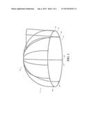
[0016] A top end 34 of the wall segments 32 is received within openings 36 of a plurality of top sleeves 35. The top end 34 is connected preferably be frictional engagement but may be connected by bolting, screwing, snap fitting, or any other conventional means. The top sleeves 35 are connected to a top ring 38 at the apex of the dome assembly 11. The top ring 38 is generally arcuate and rounded in shape and is made of a hollow aluminum alloy, but can be made of any plastic, metal, fiberglass, or any other suitable lightweight material to provide strength and durability. The top ring 38 is in parallel spaced alignment with the base ring 12. In one embodiment the openings 36 are positioned directly on the surface of the top ring 38 to receive the top end 34 of the wall segments 32 directly.
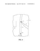
[0017] Positioned between a set of wall segments 32 is a door assembly 40 made of a hollow aluminum alloy, but can be made of any plastic, metal, fiberglass, or any other suitable lightweight material to provide strength and durability. The door assembly 40 has a cross bar 42 that is connected to a set of wall segments 32 near the top ring 38. The cross bar 42 may be connected to the wall segments 32 by a T-shaped sleeve 44 or by any other conventional manner such as by bolting, screwing, or welding. Near the center of the cross bar 42 is a support bar 46 that extends outwardly at a 90 degree angle from the cross bar 42 and generally perpendicular to the ground. Connected to the end of the support bar 46 is a frame 48, which in one embodiment is U-shaped. The top portion 50 of the frame 48 extends perpendicular to the support bar 46 and parallel to the cross bar 42. At the ends 52 of the top portion 50 of the frame 48 has a set of curved portions 52 that curves downward towards the base ring 12. Extending downward from the curved portions 52 is a set of side portions 54 that extend to openings 26 in the base ring 12.
[0018] Connected to the exterior of the dome assembly 11 is a covering 56 that in one embodiment is a one-piece cover made of vinyl coated polyester, but may be made of any durable and weather resistant material. For cold weather climates the covering 56 may be made of bubble wrap and foil to provide insulation. In an alternative embodiment the covering 56 may be made of numerous pieces connected together to cover the exterior of the dome assembly 10. The covering 56 may be attached to the dome assembly 10 by gluing, stitching, tying, or heating the covering so it adheres to the dome assembly 10.
[0019] In one embodiment the covering 56 does not cover an opening 58 of the top ring 38. The covering 56 may also have a flap 59 cut in the covering 56. This allows the opening 58 to be used for ventilation or for a heating stack.
[0020] The covering 56 may be attached to leave an opening 60 in the door assembly 40 for additional ventilation in warmer climates. In an alternative embodiment the covering 56 may cover the door opening 60 but can be removed by conventional means such as Velcro, buttons, or tying. For additional ventilation, additional flaps 59 may be cut into the covering 56.
[0021] Attached to the covering 56 is a floor 62 that covers the interior of the dwelling assembly 10 below the base ring 12. The floor 62 may be included in the one-piece covering 56 or a separate piece of material.
[0022] Positioned around the exterior of the covering 56 are a plurality of attachment devices 64 that either connect directly to the dome assembly 11 or to the covering 56. The attachment devices 64 connect to anchor devices 66 made of any heavy object such as buckets or sandbags to prevent the dwelling assembly 10 from being overturned by adverse weather conditions. In one embodiment, the attachment devices connect to anchors 66 that are placed within the ground to hold the dwelling assembly 10 in place.
[0023] An electric conduit 68 may pass through the covering 56 to the interior 70 of the dwelling assembly 10. The electric conduit 68 can bring in electrical power from portable generators 72.
[0024] Attached to the interior surface of the wall segments 32 are reinforcing loops 74. The reinforcing loops 74 can be used to hang items including a hammock 76 within the interior 70 of the dwelling assembly 10.
[0025] In operation, an individual connects the first end 16 of base ring segments 14 into the openings 22 of sleeves 20 on the second end 18 of other base ring segments 14 until a base ring 12 is formed. Wall segments 32 are connected to the base ring 12 by inserting the bottom ends 30 of the wall segments 32 into the openings 26 of connection sleeves 28. The top ends 34 of the wall segments 32 are then inserted into top sleeves 35 positioned around the top ring 38. Next, a cross bar 42 is positioned between two wall segments 32. A support bar 46 is then connected to a t-shaped sleeve 44 located on the cross bar 42. A U-shaped frame 48 is then connected to the cross bar 42 and the side portions 54 of the frame 48 are placed within openings 26 in the base ring 12 to form the door assembly 40. The individual then attaches the covering 56 and floor 62 to the exterior of the dome assembly 11. Anchoring devices 66 are then attached to the exterior of the covering 56 by attachment devices 64.
[0026] Thus provided is a dwelling assembly 10 that is easily setup, low cost, and portable. In addition, the geodesic shape of the assembly 10 provides improved weather resistance and improved circulation over previous portable dwellings. Further, the door assembly 40 and optional flaps 59 provide for additional ventilation. Finally, the placement of anchoring devices 66 placed around the exterior of the assembly 10 provides for additional stability in harsh conditions.
[0027] It will be appreciated by those skilled in the art that other various modifications could be made to the device without departing from the spirit and scope of this invention. All such modifications and changes fall within the scope of the claims and are intended to be covered thereby.
User Contributions:
Comment about this patent or add new information about this topic:
Images included with this patent application:
 |  |
 |  |
 |
| New patent applications in this class: | |
| Date | Title |
|---|---|
| 2022-09-08 | Shrub rose plant named 'vlr003' |
| 2022-08-25 | Cherry tree named 'v84031' |
| 2022-08-25 | Miniature rose plant named 'poulty026' |
| 2022-08-25 | Information processing system and information processing method |
| 2022-08-25 | Data reassembly method and apparatus |