Patent application title: SCREENED LANAI
Inventors:
Robert A. Johnson (Paxton, MA, US)
IPC8 Class: AE04B119FI
USPC Class:
Class name:
Publication date: 2015-08-06
Patent application number: 20150218791
Abstract:
A multi-seasonal lanai includes a rigid, metal support structure, or
frame, that is installed against a building over a designated area in
need of screened enclosure, such as a patio or pool. A plurality of
retractable screen assemblies is slidably coupled to and selectively
encloses the frame. A plurality of guide mechanisms serves to facilitate
displacement of the screen assemblies between an extended position, in
which the frame is substantially enclosed, and a retracted position, in
which the frame is rendered open. A plurality of fixedly mounted,
substantially enclosed, housing units retains the screen assemblies in a
relatively compact configuration when retracted and thereby protects
certain sensitive components, such as wire mesh screens, from potentially
damaging elements that are prevalent in cold weather environments, such
as snow and ice.Claims:
1. A lanai comprising: (a) an open frame; and (b) at least one screen
assembly slidably coupled to the frame and displaceable between an
extended position and a retracted position.
2. The lanai as claimed in claim 1 wherein the frame includes a plurality of beams that together define at least one opening that is selectively enclosed by the at least one screen assembly.
3. The lanai as claimed in claim 2 wherein the frame includes a plurality of parallel, spaced apart beams, each beam including a vertical segment and a horizontal segment that are joined at a rounded corner.
4. The lanai as claimed in claim 3 wherein the frame additionally includes at least one brace coupled to the plurality of beams to provide structural support to the frame.
5. The lanai as claimed in claim 1 wherein each screen assembly comprises an enlarged screen that includes a first end, a second end, and a pair of side edges.
6. The lanai as claimed in claim 1 further comprising a guide mechanism for limiting displacement of the at least one screen assembly along a defined path between the extended position and the retracted position.
7. The lanai as claimed in claim 6 wherein the guide mechanism comprises: (a) an elongated, continuous chain fixedly connected to the at least one screen assembly; and (b) a guide track coupled to the open frame, the guide track being adapted to continuously engage the chain and limit displacement of the at least one screen assembly along a defined path.
8. The lanai as claimed wherein the guide track includes at least one sprocket disposed to rotatably engage the chain and thereby limit displacement of the at least one screen assembly along a defined path.
9. The lanai as claimed in claim 8 wherein the chain comprises: (a) a series of inner side plates; (b) a series of outer side plates, and (c) a plurality of transverse cross-links connecting the series of inner and outer side plates, wherein at least one of the plurality of transverse cross-links includes a loop at one end that is coupled to the at least one screen assembly.
10. The lanai as claimed in claim 1 further comprising a substantially enclosed housing unit that is shaped to define an interior cavity dimensioned to receive the majority of the at least one screen assembly when disposed in its retracted position.
11. The lanai as claimed in claim 10 wherein the housing unit includes a drive sprocket rotatably mounted within the interior cavity, the drive sprocket selectively engaging and displacing the screen assembly between its extended and retracted positions.
12. The lanai as claimed in claim 11 further comprising a handle adapted to be coupled to the drive sprocket, wherein actuation of the handle results in rotation of the drive sprocket.
13. The lanai as claimed in claim 11 wherein the housing unit additionally includes a plurality of guide elements that together collapse the at least one screen assembly into an accordion-style configuration when disposed in its retracted position.
14. The lanai as claimed in claim 10 wherein the housing unit includes a roller rotatably mounted within the interior cavity.
15. The lanai as claimed in claim 14 further comprising an elongated, continuous cable coupled to the at least one screen assembly and the roller.
16. The lanai as claimed in claim 15 further comprising a handle adapted to be coupled to the roller, wherein actuation of the handle results in rotation of the roller.
17. The lanai as claimed in claim 15 wherein the housing unit additionally includes a plurality of guide elements that together wind the at least one screen assembly into a spiral-shaped configuration when disposed in its retracted position.
18. The lanai as claimed in claim 1 further comprising a fixedly mounted latch mechanism for selectively engaging the at least one screen assembly, the latch mechanism releasably retaining the at least one screen assembly in its extended position.
Description:
FIELD OF THE INVENTION
[0001] The present invention relates generally to the field of architectural works and more particularly to screened outdoor enclosures, such as lanais.
BACKGROUND OF THE INVENTION
[0002] A screened lanai, or lanai, is a screened structure that is mounted in an outdoor environment in abutment against the rear of a building, such as a residential structure. Together, the lanai and the building against which it is disposed create a fully enclosed, outdoor area that can be furnished and maintained as an additional room in communication with the building, such as a sunroom, patio room, enclosed porch, enclosed pool area, or the like.
[0003] Lanais are traditionally utilized in warm weather, often tropical, environments in order to enclose an outdoor area, such as a pool, and thereby keep out certain undesirable elements, such as insects, rodents, reptiles, or birds. At the same time, the screened construction of the lanai preserves the outdoor conditions for the user by enabling sunlight, wind and other desirable conditions to filter therethrough.
[0004] A lanai is typically constructed as a four-sided structure that includes three upstanding, generally vertical sidewalls and a horizontal roof, the rear of the building serving as the fourth sidewall of the enclosed structure. A lanai typically includes an open frame, or support structure, that is connected to the rear of the building over the designated outdoor area (e.g. an outdoor pool or patio), the frame being constructed of a rigid and durable material, such as aluminum. A plurality of screens are mounted into corresponding openings formed in the vertical sidewalls, with a screened door often provided in at least one sidewall to provide a means of egress from the enclosed area.
[0005] The roof of the lanai is often enclosed using either a plurality of screens or a lightweight, semi-translucent, vinyl material. However, it has been found that constructing the roof using materials that lack adequate durability poses a significant problem when the lanai exposed to certain cold weather environmental conditions, such as ice, sleet and snow. Specifically, the weight of such environmental conditions can cause the roof of a lanai to significantly cave or even tear. It is for this reason that the use of screened lanais is typically restricted to locales that experience warm weather conditions year round.
[0006] For the reason set forth above, screened lanais are not generally constructed in geographic regions that experience both warm weather and cold weather conditions year round. Rather, in such environments, outdoor enclosures are typically constructed with a more rigid and durable roof structure, such as a cement or shingled roof. However, it has been found that constructing an outdoor enclosure with a more rigid roof, or covering, introduces a number of notable shortcomings including, but not limited to, a significant increase in manufacturing costs as well as a considerable decrease in sunlight exposure within the designated area.
SUMMARY OF THE INVENTION
[0007] It is an object of the present invention to provide a new and improved lanai for enclosing an outdoor area.
[0008] It is another object of the present invention to provide a lanai as described above that includes a plurality of upstanding sidewalls and a horizontally disposed roof.
[0009] It is yet another object of the present invention to provide a lanai as described above wherein at least a portion of the plurality of upstanding sidewalls and the horizontally disposed roof is screened so as to enable sunlight, wind and other desirable environmental conditions to filter therethrough.
[0010] It is still another object of the present invention to provide a lanai as described above that is adapted to protect the horizontally disposed roof from damage in cold weather environments, thereby enabling the lanai to be installed and used in geographic regions with significantly varying climates.
[0011] It is yet still another object of the present invention to provide a lanai as described above that has a limited number of parts, is inexpensive to manufacture, is easy to install and simple to use.
[0012] Accordingly, as one feature of the present invention, there is provided a lanai comprising (a) an open frame, and (b) at least one screen assembly slidably coupled to the frame and displaceable between an extended position and a retracted position.
[0013] Various other features and advantages will appear from the description to follow. In the description, reference is made to the accompanying drawings which form a part thereof, and in which is shown by way of illustration, an embodiment for practicing the invention. The embodiment will be described in sufficient detail to enable those skilled in the art to practice the invention, and it is to be understood that other embodiments may be utilized and that structural changes may be made without departing from the scope of the invention. The following detailed description is therefore, not to be taken in a limiting sense, and the scope of the present invention is best defined by the appended claims.
BRIEF DESCRIPTION OF THE DRAWINGS
[0014] In the drawings wherein like reference numerals represent like parts:
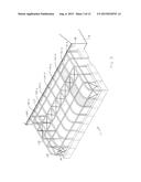
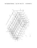
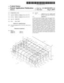
[0015] FIG. 1 is a top perspective view of a first embodiment of a lanai constructed according to the teachings of the present invention, the lanai being shown disposed in abutment against the rear of a building and over an outdoor pool, the pool and selected hidden portions of the lanai being shown in dashed form for purposes of clarity;
[0016] FIG. 2 is a fragmentary section view of the lanai shown in FIG. 1, taken along lines 2-2;
[0017] FIG. 3 is a top perspective view of a modified version of the lanai shown in FIG. 1, the lanai being shown in relation to a building and an outdoor pool represented in dashed form;
[0018] FIG. 4 is a fragmentary section view of the lanai shown in FIG. 3, taken along lines 4-4;
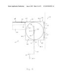
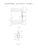
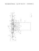
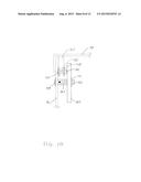
[0019] FIG. 5 is a fragmentary section view of the lanai shown in FIG. 1, taken along lines 5-5;
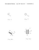
[0020] FIG. 6 is a perspective view of the spacer shown in FIG. 5;
[0021] FIG. 7 is a front view of the sprocket shown in FIG. 5;
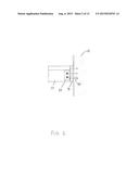
[0022] FIG. 8(a) is a front perspective view of the chain shown in FIG. 5;
[0023] FIG. 8(b) is a section view of the chain shown in FIG. 8(a), taken along lines 8b-8b;
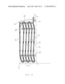
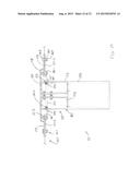
[0024] FIG. 9 is a section view of the lanai shown in FIG. 1, taken along lines 9-9, the lanai being shown with the screen assembly disposed in its retracted state;
[0025] FIG. 10 is a fragmentary section view of the lanai shown in FIG. 1, taken along lines 10-10;
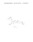
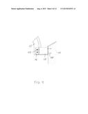
[0026] FIG. 11 is a front view of a handle for use in conjunction with the screen assembly housing shown in FIG. 10;
[0027] FIG. 12 is an enlarged, fragmentary, top plan view of the lanai shown in FIG. 1;
[0028] FIG. 13 is an enlarged section view of the latch and the residential structure shown in FIG. 12, taken along lines 13-13;
[0029] FIG. 14 is a fragmentary, section view of a second embodiment of a lanai constructed according to the teachings of the present invention, the lanai being shown disposed in abutment against the rear of a building; and
[0030] FIG. 15 is a fragmentary, section view of the lanai shown in FIG. 14, taken along lines 15-15.
DETAILED DESCRIPTION OF THE INVENTION
Construction of Lanai 11
[0031] Referring now to FIG. 1, there is shown a first embodiment of a multi-seasonal lanai constructed according to the teachings of the present invention, the lanai being identified generally by reference numeral 11. As will be explained further in detail below, lanai 11 is specifically designed to function as a fully screened enclosure around a designated outdoor area during warm weather conditions. In addition, lanai 11 is adapted to be reconfigured in anticipation of cold weather conditions to protect certain sensitive components from potentially damaging elements, such as snow, ice, wind and the like, which is a principal object of the present invention.
[0032] For ease of understanding, lanai 11 is shown connected to the rear of a two-story residential structure, or house, 13 so as to enclose a pool 15 provided in a common ground surface 17 located directly behind structure 13. However, it should be noted that lanai 11 is not limited to either the types of structures to which it can be attached or the types of items which it can enclose. Rather, it is to be understood that lanai 11 could be secured to alternative types of structures (e.g. a one-story residential structure) and enclose alternative types of items (e.g. a patio) without departing from the spirit of the present invention.
[0033] As can be seen, lanai 11 is constructed as a generally four-sided structure that includes three sidewalls 19-1, 19-2, and 19-3, which extend upward from common ground surface 17 (e.g. a patio deck), and a generally horizontal roof 21. Together, house 13, sidewalls 19, and roof 21 create an enclosure around pool 15 and define an interior space 17 that is protected from insects and other undesirable outdoor elements, which is an object of the present invention.
[0034] Lanai 11 comprises a fixed, rigid, and open support structure 25, a plurality of retractable screen assemblies 27 coupled to support structure 25, a plurality of guide mechanisms 29 to facilitate displacement of each screen assembly 27 between an extended, or closed, position and a retracted, or open, position, and a plurality of box-like, screen assembly housing units 31 for receiving and enclosing screen assemblies 27 when each is disposed in its retracted state.
[0035] Support structure, or frame, 17 is a rigid member that is fixedly secured to ground surface 17 and house 13. As can be seen, frame 25 is a largely open structural support, or skeleton, that is constructed of a material suitable for providing structural integrity and stability to lanai 11 (e.g. aluminum). Due to its structural integrity and limited surface area, frame 25 receives minimal load forces from potential harmful environmental conditions, such as wind, snow, ice and the like, and therefore is capable of remaining in its assembled state year round.
[0036] Frame 25 includes nine, equidistantly spaced, generally L-shaped and tubular, primary support members, or beams, 33-1 thru 33-9, each beam 33 including a vertical segment 35 and a horizontal segment 37 that are joined at a rounded corner 39. The free end of each vertical segment 35 is preferably permanently secured to ground surface 17 (e.g. using a bolt or cement), whereas the free end of each horizontal segment 37 is permanently secured to house 13.
[0037] Specifically, as shown in FIG. 2, the free end of each horizontal segment 37 is preferably secured to a common, elongated, aluminum end rail 41 by a right angle bracket 43. In turn, elongated end rail 41 is secured to house 13 by driving a plurality of fastening elements 45 (e.g. lag bolts) through end rail 41 and into house 13.
[0038] It should be noted that alternative means for securing lanai 11 to house 13 could be achieved without departing from the spirit of the present invention. For instance, referring now to FIGS. 3 and 4, there is shown an alternatively constructed lanai 111 that is designed principally for use with a house 113 that is one-story in height. As can be seen in FIG. 3, lanai 111 is similar to lanai 11 in that lanai 111 includes a support structure 117 that includes nine, equidistantly spaced, generally L-shaped beams 133-1 thru 133-9, each beam 133 including a vertical segment 135 and a horizontal segment 137 that are joined at a rounded corner 139.
[0039] Lanai 111 differs from lanai 11 in the means which lanai 111 is secured to house 113. Specifically, rather than secure the free end of each horizontal segment 137 to a common end rail, the free end of each horizontal segment 137 is curved slightly downward and secured to a common, horizontally disposed gutter 139 using an aluminum right angle bracket 141 and corresponding thru-bolts 143, with gutter 139 secured to housing 113 by any suitable means (e.g. using galvanized lag bolts 145).
[0040] Referring back to FIG. 1, frame 25 additionally includes a first set of equidistantly spaced vertical beams 47-1 thru 47-5, each of beams 47-1 thru 47-5 being fixedly secured at one end to ground surface 17 (e.g. using a bolt or cement) and fixedly secured at its opposite end to the underside of beam 33-1 (e.g. using right angle brackets and associated fastening elements). Together, beam 33-1 and beams 47-1 thru 47-5 define the primary support structure for sidewall 19-1.
[0041] Similarly, frame 25 includes a second set of equidistantly spaced vertical beams 47-6 thru 47-10, each of beams 47-6 thru 47-10 being fixedly secured at one end to ground surface 17 (e.g. using a bolt or cement) and fixedly secured at its opposite end to the underside of beam 33-9 (e.g. using right angle brackets and associated fastening elements). Together, beam 33-9 and beams 47-6 thru 47-10 define the primary support structure for sidewall 19-3.
[0042] To ensure adequate structural integrity, frame 25 preferably includes additional structural elements, as deemed necessary. Specifically, frame 25 includes a plurality of tubular, aluminum braces 49 that extend laterally between adjacent L-shaped beams 33 as well as between adjacent vertical beams 47. Frame 25 additionally includes a plurality of cable-type braces 51 that extend laterally between selected adjacent L-shaped beams 33 as well as between selected adjacent vertical beams 47.
[0043] As referenced briefly above, lanai 11 includes a plurality of retractable screen assemblies 27 that are coupled to frame 25. As a feature of the present invention, each screen assembly 27 is adapted to be disposed between an extended, or closed, position and a retracted, or open, position. In this manner, with each screen assembly 27 disposed in its extended position, frame 25 is fully enclosed by screens, thereby protecting interior space 17 from insects and other undesirable outdoor elements. Furthermore, with each screen assembly 27 disposed in its retracted position, frame 25 remains open and screen assemblies 27 are protected from potentially harmful load-bearing stress from common cold weather conditions, such as ice and snow.
[0044] Preferably, a screen assembly 27 is slidably mounted between each adjacent pair of L-shaped beams 33 as well as between all but one adjacent pair of vertical beams 47, the sole exception being a pivotable screen door 53 installed between one pair of adjacent vertical beams 47-8 and 47-9 to provide a means of egress from interior space 17. It should also be noted that glass sections 55-1 thru 55-3 are fixedly mounted onto frame 25 in lieu of a retractable screen assembly 27 both above door 53 and within a pair of small, irregularly-shaped openings.
[0045] For ease of illustration only, a single screen assembly 27 is shown coupled to frame 25, the screen assembly 27 being shown in its extended state. However, it is to be understood that additional similarly constructed screen assemblies 27 are preferably provided to selectively enclose the entirety of frame 25.
[0046] Each screen assembly 27 comprises an elongated, generally rectangular screen 57 that is constructed out of any suitable material that (i) permits sunlight and wind to penetrate therethrough but, at the same time, blocks insects or other relatively small undesirable elements and (ii) is relatively flexible and thereby capable of being collapsed or rolled into a compact configuration (e.g. a wire mesh material). As will be explained further below, screen 57 includes a distal end 57-1 that remains disposed, at all times, within the interior of a corresponding housing unit 31, a proximal end 57-2 adapted to be releasably secured to a latch mechanism, and a pair of opposing side edges 57-3 and 57-4.
[0047] As seen most clearly in FIG. 5, a plurality of hard rubber formed gaskets 59 are mounted over side edges 57-3 and 57-4 at defined, equidistantly spaced locations. Each gasket 59, which is generally C-shaped in transverse cross-section, is secured to side edges 57-3 and 57-4 by inner and outer fastening elements 61-1 and 61-2, each fastening element 61 comprising a carriage bolt 63, an enlarged washer 64, and a corresponding nut 65.
[0048] As noted above, a pair of opposing guide mechanisms 29 couples each screen assembly 27 to frame 25 and, in turn, facilitates displacement of screen assembly 27 between its closed and open positions. In the present embodiment, each guide mechanism 29 relies on, inter alia, complementary chains and sprockets to feed each screen assembly 27 into its designated position. However, it is to be understood that alternative types of drive, or feed, mechanisms could be used in place thereof without departing from the spirit of the present invention.
[0049] As shown in FIG. 5, each guide mechanism 29 comprises a guide track 67 coupled to frame 25 and an elongated, continuous chain 69 coupled to each screen assembly 27. In use, guide track 67 is designed to receive and engage chain 69 to maintain adequate tension in screen 57 and, in addition, feed each screen assembly 27 properly into its collapsed state within its associated housing unit 31, as will be explained further below.
[0050] It is to be understood that interior beams 33 and 47 that are not connected to door 53 (namely, beams 33-2 thru 33-8 and beams 47-2 thru 47-7) would have a pair of guide tracks 67 mounted thereon, as shown in FIG. 5. By contrast, door supporting and end beams 33 and 47 (namely, beams 33-1, 33-9, 47-1, 47-8 thru 47-10) would only have a single guide track 67 mounted thereon since only a single screen assembly 27 would be coupled thereto.
[0051] Guide track 67 preferably includes a hollow, two-piece, aluminum, outer casing 71, which is generally rectangular in transverse cross-section. Outer casing 71 is affixed by screws 72 to the exposed outer surface of each L-shaped beam 33 as well as each vertical beam 47.
[0052] Outer casing 71 is shaped to define a narrow slot, or channel, 73 that is defined, in part, by an outwardly protruding flange 75. Outer casing 71 is also shaped to include a plurality of inwardly extending, longitudinal tacks, or ribs, 77. Furthermore, a generally U-shaped molded rubber cover 79 is affixed to the outer surface of casing 71 and extends laterally outward therefrom, the function of flange 75, tacks 77 and cover 79 to become apparent below.
[0053] A hollow, cylindrical spacer 81, shown in isolation in FIG. 6, extends laterally within outer casing 71 and is rotably coupled thereto by a complementary nut 83 and screw 85. A sprocket 87, shown in isolation in FIG. 7, is axially mounted on spacer 81 and is therefore capable of rotational displacement within casing 71.
[0054] Referring now to FIGS. 5, 8(a) and 8(b), elongated, continuous chain 69 is coupled to each gasket 59 on screen assembly 27 by outer fastening element 61-2. Chain 69 includes a series of inner side plates 89-1 and a series of outer side plates 89-2, the free ends of adjacent side plates 89 being overlapped and pivotally coupled together by first and second sets of alternating, transverse cross-links, or pins, 91 and 93. As seen most clearly in FIG. 8(b), each of second set of pins 93 is extended in length and includes an enlarged loop 93-1 at its outer end. As can be appreciated, loop 93-1 is dimensioned to fittingly receive bolt 63 and thus serves as the point of connection with gasket 59.
[0055] As shown in FIG. 5, each pin 93 extends through channel 73 and is supported, as needed, by both flange 75 and cover 79. Additionally, each of the inner and outer side plates 89-1 and 89-2 align between a corresponding pair of tacks 77 in outer casing 71. Lastly, sprocket 87 is designed to engage pins 91 and 93 on chain 69. Together, the aforementioned elements retain each screen assembly 27 coupled to frame 25 and apply the required outward tension on screen 57.
[0056] Referring back to FIG. 1, lanai 11 preferably includes a plurality of box-like, screen assembly housing units 31 for receiving and enclosing screen assemblies 27 when each is disposed in its retracted state. In this manner, housing units 31 protect screen assemblies 27 when not in use (e.g. in the presence of cold weather conditions).
[0057] Each screen assembly housing unit 31 is shown permanently secured to ground surface 17 at the base of its corresponding screen assembly 27. However, it is to be understood that each unit 31 could be located at an alternative location (e.g. secured to house 13 aligned with a corresponding screen assembly 27) without departing from the spirit of the present invention.
[0058] As seen most clearly in FIG. 9, each screen assembly housing unit 31 is preferably constructed of a rigid and durable material, such as aluminum, and includes a multi-paneled, open topped, rectangular base 95 shaped to define an interior cavity 97 dimensioned to receive a corresponding screen assembly 27 while in its retracted state. Unit 31 additionally includes a cover 99 mounted over open base 95 so as to substantially enclose interior cavity 97, cover 99 being shaped to define a screen receiving opening 101 towards its rear edge and a handle receiving opening 103 towards its front edge, the function of each to become apparent below.
[0059] As seen most clearly in FIGS. 8 and 9, a single drive sprocket 105 is rotatably coupled to a side panel 95-1 of base 95 in proximity to opening 101. Drive sprocket 105 is spaced slightly away from side panel 95-1 and is axially supported by a spacer 107 that includes a splined exterior surface. Spacer 107, in turn, is rotatably secured to side panel 95-1 by an axially extending bolt 109, with sprocket 105 fixedly retained on the distal end of bolt 109 by a washer 151 and a nut 153.
[0060] A complementary, exteriorly splined bolt 155 is mounted to cover 99 by a bracket 157, bolt 155 being disposed in a close, yet slightly spaced apart relationship with exteriorly splined spacer 107. Bolt 155 is rotatably secured to the distal end of bracket 157 by a washer 159 and nut 161. Together, exteriorly splined spacer 107 and bolt 155 are disposed to receive a handle 163 for manually rotating drive sprocket 105, as will be explained further below.
[0061] Handle 163, shown in isolation in FIG. 11, includes an elongated bent bar 165 with a first end 165-1 shaped to be manually gripped by the user and a second end 165-2 that is exteriorly splined. Accordingly, to rotate drive sprocket 105 and thereby retract screen assembly 27, second end 165-2 of handle 163 is inserted through opening 103 in cover 99 and into direct engagement between exteriorly splined spacer 107 and bolt 155, with a stop 167 integrally formed onto bar 165 to contact cover 99 and thereby limit the degree of insertion of handle 163 through opening 103. By rotating first end 165-1, second end 165-2 causes both spacer 107 and bolt 155 to similarly rotate, which in turn causes drive sprocket 105 to engage and displace chain 69 (and, as a consequence, screen assembly 27).
[0062] As seen most clearly in FIG. 9, base 95 includes a plurality of passive guide sprockets 169 rotatably mounted on side panel 95-1 at defined locations, each sprocket 169 secured to panel 95-1 by any suitable means (e.g., using an elongated bolt 109, washer 151 and nut 153). Together, guide sprockets 169 are designed to engage and guide chain 69 along an accordion-style path, thereby causing screen 57 to similarly collapse in a folded, front-to-back, relationship within interior cavity 97. Additionally, base 95 includes a plurality of closely spaced pairs of tack plates 171 and arcuate end plates 173 that are secured at specified locations on side panel 95-1 to receive and help guide chain 69 along the accordion-style path defined by passive guide sprockets 169.
[0063] It should be noted that base 95 need not be limited to a design which guides chain 69 as well as screen assembly 27 along an accordion-style, or collapsed, path. Rather, it is to be understood that base 95 could be alternatively constructed to guide chain 69 along other suitable paths that would result in a relatively compact configuration of screen assembly 27 when disposed in its retracted state (e.g. along a spiral path).
Operation of Lanai 11
[0064] In use, lanai 11 is designed to operate in the following manner. Specifically, with lanai 11 constructed and connected to structure 13 in the manner set forth above, the preferred position, or state, of each screen assembly 27 is largely dependent upon the weather conditions to which it is to be exposed.
[0065] During cold weather conditions, each screen assembly 27 is preferably disposed in its retracted position, with its screen 57 collapsed, or nested, in an accordion-style configuration, as shown in FIG. 9. As such, the majority of screen 57 is retained within interior cavity 97 and is thereby protected by housing unit 31 from any potentially harmful cold weather environmental conditions, such as ice and snow. The components of lanai 11 that remain exposed to potentially harsh environmental conditions (notably, frame 25 and housings 31) are constructed of rigid and durable materials, such as metal, and have limited exposed surface area. As a result, the aforementioned components are not affected by these conditions and, as such, can remain installed year round.
[0066] It should be noted that, with screen assembly 27 disposed in its retracted position, only proximal end 57-2 of screen 57 remains outside of its corresponding housing unit 31. As seen most clearly in FIG. 12, proximal end 57-2 of screen 57 is preferably encapsulated within a hard, rubber formed gasket 175 for protective purposes. Gasket 175 is shaped to include an open hook 177 at its approximate midpoint, which is used to handle screen assembly 27 as well as latch screen assembly 27 in its expanded state, as will be explained below.
[0067] During warm weather conditions, each screen assembly 27 is preferably disposed in its extended position, thereby enclosing interior space 17 and creating an insect-free environment. To close each screen assembly 27, an extension device (not shown), such as a hooked pole, is coupled to open hook 177 on proximal end 57-2 and is manipulated to extend screen 57. As referenced above, guide track 67 ensures that chain 69 is fed along the desired path, with adequate tension continuously being applied to screen 57.
[0068] It should be noted that the present invention is not limited to the manual displacement of each screen assembly 27 to its extended position (e.g. using a pole or other similar extension device). Rather, an automated, motor-driven means for displacing each screen assembly 27 could be implemented without departing from the spirit of the present invention.
[0069] As screen assembly 27 reaches its extended position, proximal end 57-2 approaches a latch mechanism 179 that is fixedly mounted (e.g. onto residential structure 13). As seen most clearly in FIGS. 12 and 13, latch mechanism 179 includes a generally U-shaped bracket, or housing, 181 that is fixedly secured with lag bolts 183 to the desired surface (e.g. residential structure 13). A latch 185 is disposed within housing 181 and is resiliently biased upward by a spring (not shown). Latch 185 includes a tapered free end 185-1 that is externally exposed.
[0070] Accordingly, as screen assembly 27 approaches its extended position, hook 177 is aligned to directly abut against free end 185-1. Due to the beveled shape of free end 185-1, the lateral displacement force applied to hook 177 temporarily displaces latch 185 downward to the extent necessary that hook 177 can extend partially beyond latch 185. Upon the release of the displacement force, latch 185 resiliently biases to its original position, with free end 185-1 penetrating through hook 177, thereby retaining screen assembly 27 in its extended position.
[0071] To subsequently return screen assembly 27 to its retracted position, a release handle 187 is actuated on latch mechanism 179 to downwardly displace latch 185 and disengage hook 177. With proximal end 57-2 disengaged, handle 163 is inserted through opening 103 in cover 99 and is cranked to rotate drive sprocket 105 while in engagement with chain 69. As it rotates, drive sprocket 105 advances chain 69 along the accordion-style path defined by passive guide sprockets 169, tack plates 171 and end plate 173 such that the majority of screen 57 is folded within interior cavity 97, thereby completing the screen retraction process.
Alternate Constructions and Designs
[0072] The embodiment shown above is intended to be merely exemplary and those skilled in the art shall be able to make numerous variations and modifications to it without departing from the spirit of the present invention. All such variations and modifications are intended to be within the scope of the present invention as defined in the appended claims.
[0073] For instance, referring now to FIG. 14, there is shown a second embodiment of a lanai constructed according to the teachings of the present invention, the lanai being identified generally by reference numeral 211. In a similar fashion to lanai 11, lanai 211 is specifically designed to be used as a fully screened enclosure around a designated outdoor area during warm weather conditions. In addition, lanai 211 is adapted to be reconfigured in anticipation of cold weather conditions to protect certain sensitive components (e.g. screens) from potentially damaging elements, such as snow, ice, wind and the like, which is a principal object of the present invention.
[0074] Lanai 211 is similar in construction to lanai 11 in that lanai 211 comprises a fixed, rigid, and open support structure 225, a plurality of retractable screen assemblies 227 coupled to support structure 225, a plurality of guide mechanisms 229 to facilitate displacement of each screen assembly 227 between an extended, or closed, position and a retracted, or open, position, and a plurality of box-like housing units 231 for receiving and enclosing screen assemblies 227 when each is disposed in its retracted state.
[0075] As will be explained further below, lanai 211 differs principally from lanai 11 in the construction of both guide mechanism 229 as well as the construction and location of each housing unit 231.
[0076] Specifically, guide mechanism 229 differs from guide mechanism 29 in that guide mechanism 229 relies principally upon a cable/roller construction, rather than a chain/gear construction, to guide screen assemblies 227 between its retracted and extended states. The use of a cable/roller guide mechanism is desirable in that a relatively limited number of components would be required for implementation
[0077] As seen most clearly in FIG. 15, a plurality of hard rubber formed gaskets 259 are mounted over each of side edges 257-3 and 257-4 at defined, equidistantly spaced locations. Each gasket 259, which is generally C-shaped in transverse cross-section, is secured to each of side edges 257-3 and 257-4 by inner and outer fastening elements 261-1 and 261-2, each fastening element 261 comprising a carriage bolt 263, an enlarged washer 264, and a corresponding nut 265.
[0078] As noted above, guide mechanism 229 differs from guide mechanism 29 in that guide mechanism 229 comprises a guide track 267 coupled to frame 217 and an elongated, continuous cable, or cord, 269 coupled to each screen assembly 227, instead of a chain.
[0079] Guide track 267 includes a hollow, two-piece, aluminum, outer casing 271, which is generally rectangular in transverse cross-section. Outer casing 271 is affixed by screws 272 to the exposed outer surface of beam 233. Outer casing 271 is shaped to define a narrow slot, or channel, 273 that is defined, in part, by an outwardly protruding flange 275. Outer casing 271 is also shaped to include an inwardly protruding, continuous spacer 277 with a concave free end 277-1 that projects in direct alignment with slot 273. Furthermore, a generally U-shaped molded rubber cover 279 is affixed to the outer surface of casing 271 and extends laterally outward therefrom, the function of flange 275, spacer 277 and cover 279 to become apparent below.
[0080] An elongated connector, or link, 281 includes a flattened first end 281-1 that includes a transverse hole (not shown) dimensioned to receive bolt 263. As such, flattened first end 281-1 serves as the point of connection with gasket 259. Second end 281-2 of link 281 is in the form of a bulbous enlargement. A transverse bore 283 is formed in link 281 in close proximity to enlarged second end 281-2 and is dimensioned to axially receive elongated, continuous cable 269. In turn, cable 269 is wedged tightly between enlarged second end 281-2 and the combination of an oversized washer 285 and nut 287 to fixedly secure the position of each link 281 on cable 269.
[0081] Connected as such, each link 281 (and, in turn, screen assembly 227) is supported, in a first direction, by opposing flange 275 and cover 279 and is supported, in an orthogonal second direction, by opposing spacer 277 and washer 285. Together, the aforementioned elements retain each screen assembly 227 coupled to frame 217 and apply the required outward tension on screen 257.
[0082] As referenced above, lanai 211 additionally differs from lanai 11 in both the construction and mounting location of each housing unit 231. Specifically, each housing unit 231 is shown mounted at the top end of the displacement path along which its corresponding screen assembly 227 travels. For instance, as shown herein, housing 231 may be secured to residential structure 213 through gutters 214 (or some other similar support element) in order lift housings 231 and thereby limit its effect on the overall aesthetics of the intended environment.
[0083] Each box-like housing 231 differs in construction from housing 31 in that housing 231 is designed to wind cable 269 and screen assemblies 227 into a rolled configuration rather than into an accordion-style configuration. Specifically, as seen most clearly in FIG. 14, each housing 231 is preferably constructed of a rigid and durable material, such as aluminum, and includes a multi-paneled, rectangular base 295 that is shaped to define an interior cavity 297 dimensioned to receive a corresponding screen assembly 227 while in its retracted state. Base 295 is disposed at the free end of an adjacent pair of guide tracks 267 and is shaped to define a screen receiving opening 301 in its front panel 295-1 and a handle receiving opening 303 in its bottom panel 295-2, the function of each to become apparent below.
[0084] A spiral-shaped configuration of guide plates 305 is affixed to a side panel 295-3 of housing unit 231 within interior cavity 297. Additionally, an exteriorly splined center roller, or rod, 307 is rotatably coupled to side panel 295-3 of housing 231 and is connected to the free end of cable 269. A complementary pair of support plates 309 is fixedly coupled to side panel 295-3 and is disposed in close proximity to splined roller 307, the function of plates 309 to become apparent below.
[0085] A handle 311 is designed to be inserted through opening 303 in base 295 in order to rotatably drive roller 307. Handle 311 is similar to handle 163 in that handle 311 includes an elongated bent bar 313 with a first end 313-1 shaped to be manually gripped by the user and a second end 313-2 that is exteriorly splined. Accordingly, in order to rotate roller 307, second end 313-2 of handle 311 is inserted through opening 303 in base 295 and into direct engagement with exteriorly splined roller 307, the presence of support plates 309 providing the requisite opposing force onto second end 313-2 to ensure continuous engagement with roller 307. Preferably, a stop 315 is integrally formed onto bar 313 to contact bottom panel 295-2 and thereby limit the degree of insertion of handle 311 through opening 303. As part of the screen retraction process, rotation of first end 313-1 causes second end 313-2 of handle 311 to similarly rotate roller 307. Because roller 307 is coupled to the free end of cable 269, the rotation of roller 307 similarly pulls cable 269, with guide plates 305 in turn acutely directing cable 269 and screen assembly 227 along the spiral path defined by plates 305.
User Contributions:
Comment about this patent or add new information about this topic:
Images included with this patent application:
 |  |
 |  |
 |  |
 |  |
 |  |
 |  |
 |
| New patent applications in this class: | |
| Date | Title |
|---|---|
| 2022-09-08 | Shrub rose plant named 'vlr003' |
| 2022-08-25 | Cherry tree named 'v84031' |
| 2022-08-25 | Miniature rose plant named 'poulty026' |
| 2022-08-25 | Information processing system and information processing method |
| 2022-08-25 | Data reassembly method and apparatus |