Patent application title: Throw Training Device
Inventors:
Matthew D'Orazio (Columbus, OH, US)
IPC8 Class: AA63B6900FI
USPC Class:
Class name:
Publication date: 2015-08-06
Patent application number: 20150217174
Abstract:
A throw training device is provided to limit a motion of a user's
non-throwing arm while throwing an object. In one embodiment, a throw
training device comprises a harness, a cuff operable to attach to a
user's non-throwing arm, and a tension band connecting the harness to the
cuff to provide a tension to limit abduction of a user's non-throwing arm
from a user's torso.Claims:
1. A throw training device, comprising: a harness; a non-throwing arm
attachment cuff; and a tension band operatively connecting the
non-throwing arm attachment cuff to the harness.
2. The throw training device of claim 1, wherein the harness further comprises a horizontal portion operable to extend circumferentially around a user's torso, the horizontal portion further comprising a harness attachment point, the harness attachment point operable to attach the tension band to the harness.
3. The throw training device of claim 2, wherein the horizontal portion is adjustable such that a circumferential length of the horizontal portion may be varied.
4. The throw training device of claim 1, wherein the horizontal portion comprises two end portions, each end portion operable to connect to another end portion to secure the horizontal portion around a user's torso.
5. The throw training device of claim 2, wherein the harness further comprises a shoulder strap operatively connected to the horizontal portion, the shoulder strap operable to extend along an anterior portion of a user and over a user's shoulder, and further extending along a posterior portion of a user to a connection point on the posterior portion of the user, the shoulder strap further operable to position the horizontal portion at a height position relative to a user's torso.
6. The throw training device of claim 5, wherein the harness further comprises a shoulder strap adjustment, the shoulder strap adjustment operable to vary a length of the shoulder strap and vary the height position of the horizontal portion relative to the user's torso.
7. The throw training device of claim 6, wherein the harness further comprises two shoulder straps, each shoulder strap interconnected to another shoulder strap by an interconnection portion, and wherein each shoulder strap operatively connects to the horizontal portion
8. The throw training device of claim 6, wherein the harness further comprises two shoulder straps, each shoulder strap interconnected to another shoulder strap by an interconnection portion, and wherein the interconnection portion operatively connects to the horizontal portion.
9. The throw training device of claim 1, wherein the non-throwing arm attachment cuff comprises a circumferential tension, the circumferential tension operable to secure the non-throwing arm attachment cuff at a position on an arm of a user.
10. The throw training device of claim 1, wherein the non-throwing arm attachment cuff comprises a cuff adjustment, the cuff adjustment adjustable to adjust a circumferential length of the non-throwing arm attachment cuff, and operable to secure the non-throwing arm attachment cuff to an arm of a user.
11. The throw training device of claim 1, wherein the harness further comprises: a horizontal portion, the horizontal portion operable to extend circumferentially around a user's torso; shoulder straps, wherein each shoulder strap is operatively connected to the horizontal portion, and wherein each shoulder strap interconnects to another shoulder strap via an interconnection, and wherein each shoulder strap is operable to extend over a user's shoulder to vary a position of the horizontal portion relative to the user's torso; a harness attachment point, wherein the harness attachment point is operable to connect the tension band to the harness; and a cuff attachment point, wherein the cuff attachment point is operable to connect the tension band to the non-throwing arm attachment cuff; wherein the tension band limits abduction of the non-throwing arm attachment cuff from the harness.
12. The throw training device of claim 11, wherein the interconnection further comprises at least one of: a webbing; a strap; a strap and buckle; a snap connector; a strap and snap connector; a hook and loop fastener; and a strap and a hook and loop fastener.
13. The throw training device of claim 1, wherein the harness, the non-throwing arm attachment cuff, and the tension band are each comprised of a washable material.
14. The throw training device of claim 1, wherein all or portions of at least one of: the harness, the non-throwing arm attachment cuff, and the tension band, are comprised of an elastic material.
15. A throw training device, comprising: a harness, wherein the harness further comprises: a substantially horizontal strap comprising two ends, the substantially horizontal strap further operable to extend circumferentially around a user's torso, such that each end of the substantially horizontal strap further comprises a complimentary connector fitting such that one complimentary connector fitting selectively interconnects with another complimentary fitting to selectively attach the substantially horizontal strap around a torso of a user so as to secure the harness to the user's torso; a shoulder strap operatively connected to the substantially horizontal strap, wherein the shoulder strap is operable to extend over a user's thoracic region, further over a user's shoulder, and further along a posterior region of the user to a connection point, and wherein the shoulder strap is operatively connected to the connection point, and wherein the connection point is operatively connected to the substantially horizontal strap; a harness attachment point, the harness attachment point operable to secure a tension band thereto; a non-throwing arm attachment cuff, the non-throwing arm attachment cuff operable to extend around a brachial region on a non-throwing arm of the user, the non-throwing arm attachment cuff adjustable and operable to secure the non-throwing arm attachment cuff to the brachial region of a user, wherein the non-throwing arm attachment cuff comprises a cuff attachment point operable to secure a tension band thereto; and a tension band, the tension band selectively attachable to each of the harness attachment point and the cuff attachment point, such that the tension band connected to each of the harness attachment point and the cuff attachment point creates a tension so as to limit an abduction of the cuff attachment point relative to the harness attachment point.
16. The throw training device of claim 15, wherein each of the substantially horizontal strap and the shoulder strap is selectively adjustable, such that adjustment of the substantially horizontal strap varies a length of the substantially horizontal strap, and such that adjustment of the shoulder strap varies a length of the shoulder strap, wherein varying the length of the substantially horizontal strap, and varying the length of the shoulder strap varies a position of the harness relative to the user's torso.
17. The throw training device of claim 15, wherein the complimentary connector fitting comprises at least one of: a slide release/snap fit buckle; a bar slide/ladder lock and a strap; a hook and loop fastener; a frame and prong buckle and a strap; and a snap.
18. The throw training device of claim 15, wherein each of the harness, the non-throwing arm attachment cuff; and the tension band is comprised of one or more washable materials.
19. The throw training device of claim 15, wherein all or portions of at least one of: the harness, the non-throwing arm attachment cuff, and the tension band are comprised of an elastic material.
20. A method of using a throw training device, the method comprising the steps of: securing an attachment point on a non-throwing arm of a user; securing an attachment point on a torso of the user; interconnecting the attachment point on the non-throwing arm of the user to the attachment point on the torso of the user; simulating a throw with a user's throwing arm, or throwing an objection with the user's throwing arm; and providing a tension between the interconnection to limit brachial abduction of the user's non-throwing arm from the user's torso during the simulation of the throw, or the throwing of the object.
Description:
CROSS-REFERENCE TO RELATED APPLICATIONS
[0001] This application claims priority from U.S. Provisional Patent Application No. 61/935,534, filed on Feb. 4, 2014, which is incorporated by reference herein in its entirety.
BACKGROUND
[0002] American football is a popular game played by many. Football is a team sport with each team typically having eleven players on a field at one time. Player roles are largely dictated by gameplay situations, where gameplay situations require offensive players, defensive players, and special team players. Each set of players is further divided into specialized roles determined by each player's position. A quarterback is a unique, important position among the offensive players, and is usually responsible for communicating an offensive strategy to the other offensive players and for leading the execution of this offensive strategy. During gameplay, a quarterback may advance the ball himself by running, hand the ball to another player to advance the ball by running, or throw the ball to another offensive player to advance the ball by passing. Team strategy often revolves around a "running game," where the ball is advanced by the quarterback or given to another player to run the ball, or the "passing game," where the ball is passed, usually by the quarterback, to an eligible receiver.
[0003] The mechanics of a quarterback's throw are essential to a quarterback's successful passing game. Given the large number of unique roles on a football team, several different coaches specializing in different roles may work individually with one or more players to coach specific fundamentals. An offensive coordinator, a quarterback coach, or a special trainer may work with a quarterback during practice or during a training session in or out of the designated football season to improve a quarterback's throwing mechanics. Quarterbacks are often selected for the position based on a player's natural throwing aptitude, but even players with a natural passing ability may have bad passing mechanics, or have the need to improve their passing ability by improving their passing mechanics. What is needed is a training device used by pass throwing players to improve their passing mechanics.
SUMMARY
[0004] In one embodiment, a throw training device is provided, the throw training device comprising: a harness; a non-throwing arm attachment cuff; and a tension band operatively connecting the non-throwing arm attachment cuff to the harness.
[0005] In another embodiment, a throw training device is provided, the throw training device comprising: a harness, wherein the harness further comprises: a substantially horizontal strap comprising two ends, the substantially horizontal strap further operable to extend circumferentially around a user's torso, such that each end of the substantially horizontal strap further comprises a complimentary connector fitting such that one complimentary connector fitting selectively interconnects with another complimentary fitting to selectively attach the substantially horizontal strap around a torso of a user so as to secure the harness to the user's torso; a shoulder strap operatively connected to the substantially horizontal strap, wherein the shoulder strap is operable to extend over a user's thoracic region, further over a user's shoulder, and further along a posterior region of a user to a connection point, and wherein the shoulder strap is operatively connected to the connection point, and wherein the connection point is operatively connected to the substantially horizontal strap; and a harness attachment point, the harness attachment point operable to secure a tension band thereto; a non-throwing arm attachment cuff, the non-throwing arm attachment cuff operable to extend around a brachial region on a non-throwing arm of the user, the non-throwing arm attachment cuff adjustable and operable to secure the non-throwing arm attachment cuff to the brachial region on the non-throwing arm of the user, wherein the non-throwing arm attachment cuff comprises a cuff attachment point operable to secure a tension band thereto; and a tension band, the tension band selectively attachable to each of the harness attachment point and the cuff attachment point, such that the tension band connected to each of the harness attachment point and the cuff attachment point creates a tension so as to limit an abduction of the cuff attachment point relative to the harness attachment point.
[0006] In another embodiment, a method of using a throw training device is provided, the method comprising the steps of: securing an attachment point on a non-throwing arm of a user; securing an attachment point on a torso of the user; interconnecting the attachment point on the non-throwing arm of the user to the attachment point on the torso of a user; simulating a throw with a user's throwing arm, or throwing an objection with the user's throwing arm; and providing a tension between the interconnection to limit brachial abduction of the user's non-throwing arm from the user's torso during the simulation of the throw, or the throwing of the object.
BRIEF DESCRIPTION OF THE DRAWINGS
[0007] The accompanying figures, which are incorporated in and constitute a part of the specification, illustrate various example systems and methods, and are used merely to illustrate various example embodiments.
[0008] FIG. 1 illustrates a front perspective view of an example throw training device.
[0009] FIG. 2 illustrates a rear perspective view of an example throw training device.
[0010] FIG. 3 illustrates a front perspective view of an example throw training device.
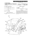
[0011] FIG. 4 illustrates a rear perspective view of an example throw training device.
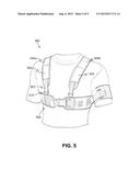
[0012] FIG. 5 illustrates a front perspective view of an example throw training device.
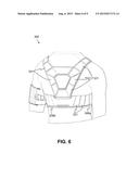
[0013] FIG. 6 illustrates a rear perspective view of an example throw training device.
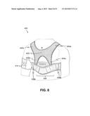
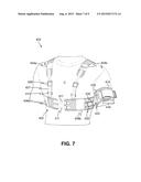
[0014] FIG. 7 illustrates a front perspective view of an example throw training device.
[0015] FIG. 8 illustrates a rear perspective view of an example throw training device.
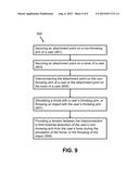
[0016] FIG. 9 is a flow chart showing a method of using a throw training device.
DETAILED DESCRIPTION
[0017] The embodiments disclosed and claimed herein depict and describe a throw training device.
[0018] FIGS. 1-8 illustrate perspective views of throw training devices 100, 200, 300, and 400. Passing accuracy and distance may be increased by throwing the ball in such a way that the ball spirals while in flight. A user rotating his/her body while throwing the ball may apply an additional amount of torque to the throwing motion, thus giving additional power that may increase the distance and velocity of a throw. Throw training devices 100, 200, 300, and 400 may help to improve a passer's body rotation and passing mechanics by limiting motion of a non-throwing arm. Throw training devices 100, 200, 300, and 400 may be used to encourage an athlete to keep an upper portion (brachial) of his/her non-throwing arm tucked against the body to provide for better body rotation mechanics and to develop non-throwing arm muscle memory.
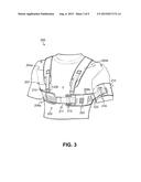
[0019] With reference to FIGS. 1 and 2, front and rear perspective views of throw training device 100 are respectively illustrated. Throw training device 100 may comprise harness 102 attached to a user's torso, and non-throwing arm attachment cuff 114 attached to a user's non-throwing arm and secured to harness 102 by a tension band 122.
[0020] Harness 102 may comprise multiple parts such as one or more shoulder straps 104a, 104b extending substantially vertically over a user's thoracic (chest) area C and over a user's shoulders S, extending along a user's back B. While harness 102 may be realized with one shoulder strap, harness 102 may be substantially symmetrical about a user's body midline, with a right side portion 103a and a left side portion 103b including shoulder straps 104a and 104b. Shoulder straps 104a and 104b may be joined together on a user's back by webbing 105. In one embodiment, webbing 105 is of an elastic material that allows webbing 105 to stretch and contract to provide lateral/medial movement of one shoulder strap (e.g. 104a) relative to the other should strap (e.g.104b) and vice-versa, so as to provide increased user comfort, as well as providing adjustability of harness 102 to fit users of different body sizes. In another embodiment, webbing 105 is relatively inelastic and does not stretch. Shoulder straps 104a and 104b may comprise shoulder strap adjustment hardware 106 for a vertical adjustment of harness 102 relative to a user's torso. In one embodiment, adjustment hardware 106 is an integrated elastic strap integrated in shoulder straps 104a and 104b to allow for simple expansion in a length of shoulder strap 104 to provide a degree of flexibility for fitting users of different body sizes, and provide user comfort while wearing harness 102. Harness 102 may further comprise substantially horizontal portions 108a and 108b extending laterally from shoulder strap 104a and 104b on a back side (posterior) of a user and wrapping circumferentially around a user to join respective portions of shoulder straps 104a and 104b on a user's front side (anterior). One or more connectors 112 may attach to horizontal portion 108a and shoulder strap 104a so as to secure horizontal portion 108a and shoulder strap 104a to complimentary locations on horizontal portion 108b and shoulder strap 104b, so as to ultimately secure harness 102 to a user's body. In one embodiment, harness 102 is similar to a vest, with a user's arms extending through a void (e.g. armholes) 109 bounded by horizontal portions 108a/108b and shoulder straps 104a/104b respectively, with right side portion 103a of harness 102 being secured to left side portion 103b of harness 102 about a user's chest area C. In another embodiment, right side portion 103a of harness 102 is secured to left side portion 103b of harness 102 on a user's back B. Connector 112 may be a slide release/snap fit buckle, with complimentary buckle fittings 112a and 112b. Fitting 112a may be a female portion that accepts male portion 112b. Male portion 112b may slide into female portion 112a with a male portion having tabs that lock male portion 112b in place relative to female portion 112a when both portions are fully engaged with one another. Complimentary buckle fitting 112a and 112b may operatively connect to both horizontal portions 108a, 108b and shoulder straps 104a, 104b via girth adjustment straps 111. Strap adjustment hardware 110 may be used to slacken/tighten girth adjustment straps 111 so as to vary a distance between right side portion 103a and left side portion 103b to provide a custom fit of harness 102 for users of different girths. In one embodiment, strap adjustment hardware 110 is a slide, bar slide/ladder lock, or belt trim, where length of girth adjustment strap 111 is varied by weaving girth adjustment strap 111 through and around strap adjustment hardware 110.
[0021] Non-throwing arm attachment cuff 114 may attach to a brachial (upper-arm) portion of a user's non-throwing arm. In one embodiment, non-throwing arm attachment cuff attaches to a user's non-throwing arm in a location between a user's shoulder and a user's elbow on a user's non-throwing arm. Non-throwing arm attachment cuff 114 may include a cuff adjustment 116 for slackening and tightening a circumference of non-throwing arm attachment cuff 114 around a brachial portion of a user's non-throwing arm. In one embodiment, cuff adjustment 116 includes strap 115 and loop 117 for varying a circumference of non-throwing arm attachment cuff 114. In this embodiment, strap 115 passes through and around loop 117 and pulled to tighten non-throwing arm attachment cuff 114, with strap 115 being secured to itself via a snap, a hook and loop fastener, and the like, once non-throwing arm attachment cuff 114 has been properly adjusted.
[0022] Harness 102 and portions thereof such as shoulder straps 104a, 104b, horizontal straps 108a, 108b, webbing 105, girth adjustment straps 111, non-throwing arm attachment cuff 114, and strap 115 may be of a material that may breathable, durable, and comfortable for extended, and vigorous use during a user's training. Additionally, harness 102 and the aforementioned portions thereof may be of a material that is easily washable or capable of being laundered. In one embodiment, harness 102 and the aforementioned portions thereof are made of a heavy, natural material such as cotton, linen, canvas, hemp, and the like. In another embodiment, harness 102 and the aforementioned portions thereof are made of a synthetic material such as spandex, elastic, polyester, nylon, Kevlar®, Cordura®, and the like. Material selection for harness 102 and the aforementioned portions thereof may be based on training environment, training duration, age and skill level of a user, intended harness lifespan, and like factors. In one embodiment, harness 102 and the aforementioned portions thereof are made of different materials. In another embodiment, harness 102 and the aforementioned portions thereof are made of the same material. Harness 102 and the aforementioned portions thereof may be reinforced by known garment production techniques to provide durability. Such material reinforcement techniques may include one or more techniques such as: an addition of seams, material layering, stitching, adhesives, mechanical fasteners such as rivets, and the like.
[0023] Throw training device 100 may include a tension band 122 secured to one or more harness attachment points 120 and one or more cuff attachment points 118 to provide a tensioned connection between non-throwing arm adjustment cuff 114 and harness 102. Tension band 122 may limit brachial abduction (i.e. movement away) of a user's non-throwing arm from a user's torso. Likewise, tension band 122 may encourage brachial adduction (i.e. movement toward) of a user's non-throwing arm towards a user's torso.
[0024] Tension band 122 may be of a flexible material that provides adequate tension when stretched, such as rubber or elastic fabric, or tension band 122 may be of an inelastic material, where brachial abduction of a user's non-throwing arm is limited by tension band length. In embodiments where tension band 122 is of an elastic material, material selection for tension band 122 may be used to vary tension in tension band 122. For example, a material with a greater resistance when elastically deformed, (i.e. stretched), may be used to better limit brachial abduction of a user's non-throwing arm from a user's torso. Tension band 122 may be of an elastic material, and limited in length to limit brachial abduction of a user's non-throwing arm from a user's torso. In one embodiment, tension band 122 includes a female snap fitting 123a which mates with a complimentary male snap fitting 123b on harness attachment point 120 to vary a length of tension band 122. Tension band may be permanently attached, or removably attached (i.e. selectively removable) at either harness attachment point 120, and cuff attachment point 118.
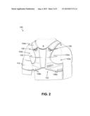
[0025] With reference to FIGS. 3 and 4, respective front and rear perspective views of example throw training device 200 are illustrated. Similar to throw training device 100, throw training device 200 may include harness 202 comprising shoulder straps 204a and 204b extending over a user's chest C and shoulder portions S, and joining at a central back portion 205 and on a user's back B. Central back portion 205 may further connect to a medial horizontal portion 208 which may extend into both right side horizontal portion 208a, and left side horizontal portion 208b, and extend circumferentially around a user's torso to operatively connect to respective shoulder straps 204a and 204b via adjustment hardware 206 on a user's front side. Adjustment hardware 206 may be used to vary a length of shoulder straps 204a and 204b, and may include height adjustment strap 207 and buckle/loop 213 to vary a length of shoulder straps 204a and 204b, so as to move harness 202 up and down a user's torso, and thus vary a superior/inferior position (i.e. height) of harness 202 on a user's body. In this way, harness 202 may be adjusted to accommodate users of different heights and torso lengths. A distal portion of height adjustment strap 207 may pass through and around buckle/loop 213, and secure to another area of height adjustment strap 207 or to shoulder straps 204a and 204b using a common connection hardware such as a snap, hook and loop fastener, and the like. For example, distal end of height adjustment strap 207 may have Velcro® on one side thereof, and after passing through and around buckle/loop 213, distal end may be secured to another location of height adjustment strap having complimentary Velcro® thereon. Right side horizontal portion 208a and left side horizontal portion 208b may secure to one another via girth adjustment strap 211 and buckle 212. Harness 202 may be adjusted for users with torsos of varying girth by using girth adjustment strap 211 and buckle 212. A distal portion of girth adjustment strap 211 may extend through, and around buckle 212 and be secured to another portion of girth adjustment strap 211 using a common connector hardware such as a snap, hook and loop fastener, and the like. Central back portion 205 may be permanently affixed to medial horizontal portion 208 at connection 219 via a fabric joining technique such as stitching, weaving, adhesive, and the like, or may be removably attached, for example, using a common connector such as a snap, button, buckle, hook and loop fastener, and the like. Removable attachment of components on harness 102 may allow modular portions (i.e. horizontal portions 208, 208a, 208b, shoulder straps 204a,204b, and central back portion 205) to interchange with other modular portions to vary a size of harness 102. Portions of harness 202 may be paneled with paneling 221 so as to provide additional strength and flexibility to harness 202. Harness 202 may comprise the same or similar materials used to construct harness 102, as described above.
[0026] Similar to throw training device 100 described above, throw training device 200 may include a tension band 222 secured to one or more harness attachment points 220 and one or more cuff attachment points 218 to provide a tensioned connection between non-throwing arm cuff 214 and harness 202 to limit brachial abduction of a user's non-throwing arm from a user's torso. Cuff 214 may be of an elastic material that allows for circumferential elastic expansion such that a user may slide cuff 214 over a non-throwing arm, with a circumferential elasticity used to hold cuff 214 about a brachial region of a user's arm. Material selection of cuff 214 to select a material with an adequate elasticity may be used to limit or eliminate longitudinal movement of cuff 214 about a brachial region of a user's non-throwing arm.
[0027] As described above for tension band 122, tension band 222 may be of an elastic or inelastic material, and tension may be varied by either selecting a material with desired elastic properties, varying a length of tension band 222, or any combination thereof. In one embodiment, tension band 222 is a strap permanently attached to harness 202 at harness attachment point 220, and cuff attachment point 218 is a buckle/loop. In this embodiment, tension is varied by passing a distal portion of tension band 222 through and around buckle/loop 218 and securing the distal portion of tension band 222 back to another portion of band 222 via a common connection hardware such as a snap, hook and loop fastener, and the like to vary a length of tension band 222. Material selection of tension band 222 for a material of desired elasticity and resistance may also be used to vary tension, and thus limit a brachial abduction of a user's non-throwing arm.
[0028] With reference to FIGS. 5 and 6, respective front and rear perspective views of example throw training device 300 are illustrated. Throw training device 300 is similar in design and function of throw training device 200 but may include additional features such as strap sheath 324 on shoulder straps 304a and 304b on harness 302. Strap sheath 324 may be allowed to move longitudinally along shoulder straps 304a, 304b such that when harness 302 is adjusted and sized for a proper height fit of a user, a distal portion of height adjustment strap 307, after passing through and around buckle/loop 313, is secured to another portion of height adjustment strap 307 using a common connector hardware such as a snap, hook and loop fastener, and the like, with strap sheath 324 pulled over a strap to strap connection point of height adjustment strap 307 to prevent disengagement of a strap to strap connection point on height adjustment strap 307 once a proper height adjustment of harness 302 is made, and during use of throw training device 300. Additional paneling 321 may be used to increase strength, flexibility, and aesthetic appearance of throwing training device 300, as well as simplifying a mass-production or manufacture of throw training devices in different size ranges. For example, modular base components may comprise panels 321 to produce modular components in variable sizes, and thus throw training devices in variable sizes (e.g. size large may comprise a horizontal portion 308a of six panels 321 of similar size, whereas a size small may comprise a horizontal portion 308a of three panels 321 of similar size, etc.).
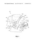
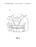
[0029] With reference to FIGS. 7 and 8, respective front and rear perspective views of example throw training device 400 are illustrated. Similar to previous embodiments, throw training device 400 may include harness 402 comprising shoulder straps 404a, 404b extending over a user's thoracic/chest region C and over shoulders S to back B. Shoulder straps 404a, 404b may interconnect to one another via bib-type section 405 which connects shoulder straps 404a, 404b at a centralized location on a user's back. Shoulder straps 404a, 404b may diverge from bib-type section 405 and extend in an inferior direction until they connect with a medial horizontal portion 408. Right side horizontal portion 408a, and left side horizontal portion 408b may extend laterally from medial horizontal portion 408 and extend circumferentially around a user's torso to join to each other near a midline area of a user's chest C.
[0030] In one embodiment, a connection formed between height adjustment strap 407 and buckle 413 operatively connect shoulder straps 404a, 404b to horizontal portions 408a, 408b. In addition to height adjustment strap 407 and buckle 413 used to adjust a fit of shoulder straps 404a, 404b on users of different sizes, a bar slide/ladder lock 426 may be used to further adjust height adjustment straps 407. In one embodiment, height adjustment strap 407 is of a finite length and permanently secured by stitching to shoulder straps 404a, 404b, such that a user need only adjust bar slide/ladder lock 426 to vary a fit of shoulder straps 404a, 404b, and height adjustment of harness 402, without a need to further secure height adjustment strap 407 after making a height adjustment of harness 402. In another embodiment, a distal end of height adjustment strap 407 is passed through and around buckle/loop 413, weaved through bar slide/ladder lock 426 with distal end of height adjustment strap 407 either secured by bar slide/ladder lock 426, or secured to another part of height adjustment strap 407 by a common connection hardware such as a snap, hook and loop fastener, and the like. Buckle 413 may be secured either directly to horizontal portions 408a, 408b, or operatively connected to, and offset from horizontal portions 408a, 408b at some distance by a strap as illustrated.
[0031] Horizontal portions 408a, 408b may connect to each other via a girth adjustment strap 411. In one embodiment, girth adjustment strap 411 comprises a connection hardware on a portion thereof that secures to a complimentary connection hardware on a portion of left-side horizontal portion 408b. In this embodiment, a connection hardware is a hook and loop fastener such as Velcro®.
[0032] Throw training device 400 may comprise the same, or similar materials as previously described embodiments.
[0033] Tension band 222 may likewise comprise similar materials as previously described embodiments. Similar to previously described throw training devices, throw training device 400 may include a tension band 422 secured to a harness attachment point 420, and a cuff attachment points 418 to provide a tensioned connection between non-throwing arm cuff 414 and harness 402 to limit brachial abduction of a user's non-throwing arm from a user's torso. Cuff 414 and its adjustment and attachment around and to a user's non-throwing arm, may use a cuff adjustment 416, that is similar to cuff adjustment 116, as described above.
[0034] Throw training device 400 may use one or more tension bands 422 either alone, or in combination with one another to limit brachial abduction of a user's non-throwing arm from a user's torso, and encourage brachial adduction of a user's non-throwing arm towards a user's torso.
[0035] In one embodiment, tension band 422 is a color-coded, elastic strap permanently attached to cuff attachment points 418, and removably attachable to harness attachment point 420. Harness attachment point 420 may interface with connection hardware 428 on tension band 422. In one embodiment, connection hardware 428 attaches to harness attachment point 420 via a strap 430 that may be either varied in length to further affect a tension of tension band 422, or may subdivided into discrete sections like a daisy chain construction (not shown), wherein connecting connection hardware 428 into each discrete subsection of a daisy chained strap 430 varies a tension of tension band 422. A daisy-chained subdivision of strap 430 may also provide a capability of attaching multiple tension bands 422 to hardness attachment point 420. Tension band 422 may comprise springs. In one embodiment, tension band 422 is one or more rubber bands. Tension bands 422 may be color coded to indicate different levels of tension. In one embodiment, tension bands 422 are all of a same tension, and one or more tension bands 422 are added until a desired tension is achieved. For example, if each tension band 422 provides five pounds of resistance, three tension bands 422 would be used to provide fifteen pounds of resistance. In another embodiment, tension band 422 is multicolored. In this embodiment, one end of tension band 422 is colored green, a middle portion of tension band 422 is colored yellow, and another end of tension band 422 is colored red. A person observing a user of throw training device 400 using a multicolored tension band 422 may be able to better observe an abduction of a user's non-throwing arm from a user's torso depending on a color of tension band 422 observed. For example, a multicolored tension band 422 closest to a user's body may be green such that an observer of a user using throw training device 400, where a user has little or no non-throwing arm abduction, may only observe a green color on tension band 422. In contrast, an observer of a user using throw training device 400, where a user has significant non-throwing arm abduction, may see yellow or red, where a red portion of multicolored tension band 422 is attached closest to a user's non-throwing arm.
[0036] Non-throwing arm adjustment cuff 414 and portions of harness 402 may include one or more cuff attachment points 418 and one or more harness attachment points 420 respectively for securing an end of one or more tension bands 422 thereto. In one embodiment, cuff attachment points 418 and harness attachment points 420 are rings or loops used for quickly connecting, and disconnecting one or more tension bands 422 thereto. End portions of tension bands 422 may comprise quick connection hardware such as spring loaded carabiners, hooks, clasps, or like hardware, for quick and secure connection of tension bands 422 to attachment points 418 and 420. In one embodiment, cuff attachment points 418 and harness attachment points 420 are adjustable relative to non-throwing arm adjustment cuff 414 and harness 402 respectively, for adjusting a size of throw training device 400 to accommodate different body sizes and body geometries for a variety of users. In one embodiment, harness attachment points 420 are around an axillary portion (armpit) of a user's torso and cuff attachment points 418 correspond to an area on a user's brachial region that abuts axillary portion of a user's torso when a user's non-throwing arm is at rest. In another embodiment, harness attachment point 420 is around a user's waist portion.
[0037] Referring now to FIG. 9, a flow chart of an example method (900) for using a throw training device is provided. A method of using a throw training device (900) may comprise the steps of: securing an attachment point on a non-throwing arm of a user (901); securing an attachment point on a torso of a user (903); interconnecting an attachment point on the non-throwing arm of a user to the attachment point on the torso of a user (905); simulating a throw with a user's throwing arm; or thrown an object with the user's throwing arm (907); and providing a tension between the interconnection to limit brachial abduction of the user's non-throwing arm from the user's torso during the simulation of the throw, or the throwing of the object (909).
[0038] Unless specifically stated to the contrary, the numerical parameters set forth in the specification, including the attached claims, are approximations that may vary depending on the desired properties sought to be obtained according to the exemplary embodiments. At the very least, and not as an attempt to limit the application of the doctrine of equivalents to the scope of the claims, each numerical parameter should at least be construed in light of the number of reported significant digits and by applying ordinary rounding techniques.
[0039] Notwithstanding that the numerical ranges and parameters setting forth the broad scope of the invention are approximations, the numerical values set forth in the specific examples are reported as precisely as possible. Any numerical value, however, inherently contains certain errors necessarily resulting from the standard deviation found in their respective testing measurements.
[0040] Furthermore, while the systems, methods, and apparatuses have been illustrated by describing example embodiments, and while the example embodiments have been described and illustrated in considerable detail, it is not the intention of the applicants to restrict, or in any way limit, the scope of the appended claims to such detail. It is, of course, not possible to describe every conceivable combination of components or methodologies for purposes of describing the systems, methods, and apparatuses. With the benefit of this application, additional advantages and modifications will readily appear to those skilled in the art. Therefore, the invention, in its broader aspects, is not limited to the specific details and illustrative example and exemplary embodiments shown and described. Accordingly, departures may be made from such details without departing from the spirit or scope of the general inventive concept. Thus, this application is intended to embrace alterations, modifications, and variations that fall within the scope of the appended claims. The preceding description is not meant to limit the scope of the invention. Rather, the scope of the invention is to be determined by the appended claims and their equivalents.
[0041] As used in the specification and the claims, the singular forms "a," "an," and "the" include the plural. To the extent that the term "includes" or "including" is employed in the detailed description or the claims, it is intended to be inclusive in a manner co-extensive with the term "comprising," as that term is interpreted when employed as a transitional word in a claim. Furthermore, to the extent that the term "or" is employed in the claims (e.g., A or B) it is intended to mean "A or B or both." When the applicants intend to indicate "only A or B, but not both," then the term "only A or B but not both" will be employed. Similarly, when the applicants intend to indicate "one and only one" of A, B, or C, the applicants will employ the phrase "one and only one." Also, to the extent that the terms "in" or "into" are used in the specification or the claims, it is intended to additionally mean "on" or "onto." To the extent that the term "selectively" is used in the specification or the claims, it is intended to refer to a condition of a component wherein a user of the apparatus may activate or deactivate the feature or function of the component as is necessary or desired in use of the apparatus. To the extent that the term "operatively connected" is used in the specification or the claims, it is intended to mean that the identified components are connected in a way to perform a designated function. Finally, where the term "about" is used in conjunction with a number, it is intended to include ±10% of the number. In other words, "about 10" may mean from 9 to 11.
User Contributions:
Comment about this patent or add new information about this topic:
Images included with this patent application:
 |  |
 |  |
 |  |
 |  |
 |  |
| New patent applications in this class: | |
| Date | Title |
|---|---|
| 2022-09-08 | Shrub rose plant named 'vlr003' |
| 2022-08-25 | Cherry tree named 'v84031' |
| 2022-08-25 | Miniature rose plant named 'poulty026' |
| 2022-08-25 | Information processing system and information processing method |
| 2022-08-25 | Data reassembly method and apparatus |
| New patent applications from these inventors: | |
| Date | Title |
|---|---|
| 2015-11-26 | Throw training device |