Patent application title: COOLING SYSTEM FOR CONTAINER TREATMENT ASSEMBLIES
Inventors:
Roland Kerscher (Obertraubling, DE)
IPC8 Class: AF28D1500FI
USPC Class:
Class name:
Publication date: 2015-07-23
Patent application number: 20150204616
Abstract:
Assembly for the beverage processing industry having several individual
machines, including at least a blow molding machine, a labeling machine
and a filler, including a common water cooling circuit with a radiator
for components of the individual machines to be cooled and a
corresponding method for cooling such an assembly.Claims:
1. An assembly for the beverage processing industry, comprising a
plurality of individual machines, including at least a blow molding
machine, a labeling machine and a filler, and a common water cooling
circuit with a radiator for components of the individual machines to be
cooled.
2. The assembly according to claim 1, and the water cooling circuit comprises at least one supply line for water for each individual machine.
3. The assembly according to claim 2, and a heat exchanger is provided in at least one individual machine and connected to the at least one supply line.
4. The assembly according to claim 2, and a main line is provided that distributes water from the radiator in the water cooling circuit and is connected to the at least one supply line.
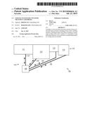
5. The assembly according to claim 1, and an air-water heat exchanger is provided in at least one individual machine and connected to the water cooling circuit and/or that a cold plate being connected to said water cooling circuit is provided in at least one of said individual machines.
6. The assembly according to claim 1, and flow controllers that can control the cooling capacity supplied to an individual machine are provided in the water cooling circuit.
7. The assembly according to claim 1, and the individual machines are configured as processing units connected in series which can perform sequential processes.
8. A method for cooling an assembly in the beverage processing industry having several individual machines, comprising cooling the individual machines of the assembly by a common water cooling circuit.
9. A method according to claim 8, and supplying water to the individual machines via supply lines.
10. The method according to claim 9, and the water exchanges heat with a heat exchanger in the individual machine and cools the individual machine.
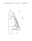
11. The method according to claim 9, and transporting the water through a main line into the supply lines.
12. The method according to claim 8, and the cooling of the individual machine is effected by heat exchange of the water with air in an air-water heat exchanger.
13. The method according to claim 8 and controlling the supplied cooling capacity for each individual machine.
Description:
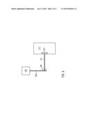
CROSS-REFERENCE TO RELATED APPLICATION
[0001] The present application claims priority to German Application No. 10 2014 100 733.6, filed Jan. 23, 2014. The priority application, DE 10 2014 100 733.6 is hereby incorporated by reference.
FIELD OF THE DISCLOSURE
[0002] The present disclosure relates to a cooling system for container treatment assemblies in the beverage processing industry.
BACKGROUND
[0003] Known container treatment assemblies are in part composed of several container treatment machines. They comprise, for example, fillers or blow molding machines or sealers, but are not limited thereto. Cooling these individual machines or processing units also in common container treatment assemblies, in which these process units are arranged together, usually takes place by the use of individual cooling systems which are configured such that they fulfill the cooling requirements of the individual machine with which they are associated. For example, water cooling systems having a very high capacity are used for blow molding machines because the individual components of the blow molding machine, in particular the blow molds, need to be cooled down rapidly but have a high heat capacity, and a large amount of heat must therefore be dissipated. Other machines In contrast, such as labeling machines or fillers, are in part cooled only with air as they generally produce less waste heat that must be dissipated by a cooling system.
[0004] A large number of different cooling systems can therefore be needed to cool the individual machines of the entire assembly, which involves a very high maintenance effort and can be confusing in terms of process technology.
SUMMARY OF THE DISCLOSURE
[0005] Starting out from prior art, the present disclosure has as one aspect providing a cooling system for assemblies for the beverage processing industry that enables efficient cooling and is also cost-efficient.
[0006] The assembly according to the disclosure for the beverage processing industry comprises several individual machines, including at least a blow molding machine, a labeling machine and a filler and provides that the assembly comprises a common water cooling circuit with a radiator for components of the individual machines to be cooled. Only a single cooling system with a radiator is therefore required for the entire assembly, even if the latter comprises several individual machines, which results in significant reduction of the complexity of the entire cooling system for the assembly and is also more cost-efficient than separate cooling systems for individual machines. Due to the use of a water cooling system, individual machines with a high cooling demand can also be sufficiently cooled.
[0007] According to one embodiment, the water cooling circuit comprises at least one supply line for water for each individual machine. By having, at least in part separate supply lines, the cooling medium, presently water, can be selectively supplied to the individual machines.
[0008] It can be provided that a heat exchanger is included in at least one individual machine and connected to the supply line. Providing heat exchangers in the individual machines enables providing smaller special cooling circuits within the individual machines, the waste heat of which can by the common cooling system be dissipated via the heat exchanger.
[0009] In one advantageous embodiment of the disclosure, the assembly includes a main line that distributes the water from the radiator in the cooling circuit and is connected to the supply lines. Providing a main line enables passing a significant amount of water or cooling medium which can as needed be supplied via the supply lines to the individual machines.
[0010] In one embodiment, an air-water heat exchanger is provided in at least one individual machine and is connected to the water cooling circuit and/or that a cold plate being connected to the water cooling circuit is provided in at least one of the individual machines. This configuration of the cooling systems in the individual machines can allow for certain requirements of the latter to be met in terms of the cooling.
[0011] Further, flow controllers can be included in the water cooling circuit and can control the cooling capacity supplied to an individual machine. If the required cooling capacity for a certain individual machine varies, for example depending on capacity utilization, then the supply of water as a cooling medium and thereby the supplied cooling capacity can there be regulated, resulting in a more energy-saving production.
[0012] The assembly can include that the individual machines are configured as processing units connected in series which can perform sequential processes. The advantages of the cooling system according to the disclosure can also be used in complex composite assemblies in which a container can be transported from the production to completion and filling.
[0013] The disclosure further comprises a method for cooling an assembly in the beverage processing industry with several individual machines where the individual machines in the assembly are cooled by a common water cooling circuit. This method of cooling the individual machines of the assembly is more efficient precisely in terms of process technology and is further more cost-efficient.
[0014] In one embodiment of the method, water is supplied to the individual machines via supply lines. The separate supply of the water as a cooling medium to the individual machines optionally allows selective control of the cooling process of some individual machines, without affecting the cooling of the remaining individual machines, this entailing a high degree of flexibility.
[0015] It can also be provided that the water exchanges heat with a heat exchanger in the individual machine and cools the individual machine. The use of the heat exchanger allows removal of waste heat that is generated in the individual machine and removed from the individual machine, for example, via an internal cooling system.
[0016] In a further embodiment, the method provides that the water is transported through a main line into the supply lines. Transport of water as a cooling medium through a main line allows for a high maximum cooling capacity.
[0017] It can be advantageous if cooling the individual machine is effected by heat exchange of the water with air in an air-water heat exchanger. The waste heat generated in one or more individual machines and removed via a separate internal air cooling system is removed by the following water cooling circuit of the individual machine or the individual machines.
[0018] It can furthermore be provided that the supplied cooling capacity is controlled for each individual machine. This enables cost-efficient and selective cooling of the individual machines and their components.
BRIEF DESCRIPTION OF THE FIGURES
[0019] FIG. 1 shows a schematic representation of an assembly according to the disclosure.
[0020] FIG. 2 shows a schematic representation of a further embodiment of an assembly according to the disclosure.
[0021] FIG. 3 shows a schematic representation of an embodiment of the supply line.
DETAILED DESCRIPTION
[0022] FIG. 1 shows a schematic representation of an assembly 100 according to the disclosure for the beverage processing industry. This is to include all assemblies that are used for the production of e.g. containers, such as bottles, but also assemblies that allow labeling or further treatment of containers produced as well as assemblies that accomplish filling, sealing and packaging of the containers. The assembly 100 according to the disclosure comprises a number of individual machines which are combined to form an assemblage 110.
[0023] These individual machines 111-114 comprise at least a blow molding machine, a labeling machine and a filler.
[0024] Other container treatment machines, such as direct printing machines, sterilization devices or the like are also conceivable. Also conceivable are machines from the packaging and palletizing technology. The individual machines 111-114 can be interconnected by transportation devices for containers. This includes, for example, conveyors or mounts that transport the containers according to the neck-handling method.
[0025] According to the disclosure, the assembly 100 further comprises a cooling system 115.
[0026] This cooling system 115 being common for the individual machines 111-114 comprises a radiator 120 which is via a water cooling circuit connected to the individual machines 111-114 in the assemblage 110. This connection of the radiator 120 to the individual machines 111-114 can be implemented by in part separate supply lines 121-124. These supply lines 121-124 there transport cooling water from the radiator 120 to the individual machines 111-114 and can remove "used" cooling water, i.e. cooling water that was used to cool the individual machines 111-114 or components thereof, respectively. This removal, however, there does not need to be to the radiator. The used cooling water can also be disposed of or provided to other individual machines for heating purposes. These individual machines can, but do not need to be part of the assemblage 110.
[0027] Although the supply lines 121-124 are in FIG. 1 illustrated all being separated from each other, it can also be provided that the supply lines 121-124 at least in part coincide and only at certain points branch off from each other to supply the individual machines 111-114 with cooling water. Furthermore, each supply line 121-124 is in FIG. 1 illustrated as being a single line which can transport cooling water following the directions of the arrows towards the individual machines and then away from them. It can also be provided, however, that the return transport is effected via a different path than the supply transport of the cooling water. It can, for example, be provided that the supply of cooling water to the individual machines 111-114 is effected in supply lines 121-124 separate from each other, as shown, whereas the return of the used cooling water to the radiator 120 is effected via a common return line.
[0028] FIG. 2 shows a further embodiment of the assembly 100 according to the disclosure. It is therein provided that a main line 250 originates from the radiator and can transport cooling water away from the radiator and return used cooling water back to the radiator. As already described in FIG. 1, it can also be provided that the return of the cooling water is effected via a different path, therefore not via the main line 250 shown. The previously described supply lines 121-124 branch off from the main line 250 at several points. They supply the cooling water to the individual machines 111-114 and can optionally also transport it away from the latter.
[0029] It can be provided that the individual machines 111-114 of the assemblage 110 are equipped with internal cooling systems 231-234. These internal cooling systems can have very different configurations. It can be provided, for example, as part of a blow molding machine, that a plurality of cooling circuits are available which transport away the waste heat arising in the blow molds. A corresponding blow molding machine 111 would there comprise a cooling system 231 in which a separate cooling circuit is provided with a large number of branch-offs corresponding to the number of blow molds. The heat absorbed by the cooling system can then, for example, via a heat exchanger in the cooling system 231, be transferred to the cooling water which is transported through the supply line 121, whereby it is removed from the individual machine 111.
[0030] Other individual machines, however, such as labeling machines, can also use a different form of cooling. It can be provided that a labeling machine 113 has an independent or internal air cooling system 233. There as well, an air-water heat exchanger can be provided which transfers the waste heat of the components absorbed by the air cooling circuit in the labeling machine 113 to the cooling water being transported in the supply line 123, whereby the waste heat of the labeling machine is with the removal of the cooling water through the supply line 123 removed therefrom.
[0031] Many further embodiments are there conceivable, for example, using cold plates or other cooling systems. According to the disclosure, all internal cooling systems are conceivable for the individual machines 111-114, provided that waste heat being absorbed from the latter can be transferred to the cooling water in the supply lines 121-124, for example, via suitable heat exchangers. The use of heat exchangers can, but need not be dispensed with if the internal cooling system is also a water cooling system. In this case, the cooling circuit in the individual machine can either transfer the waste heat absorbed from the components via a heat exchanger to the cooling water in the cooling circuit 115 or the water from the cooling circuit 115 can be directly used for cooling the components of the individual machines in that it is used in the internal cooling circuit.
[0032] FIG. 3 shows an embodiment for the supply of cooling water from the radiator 120 to an individual machine 111 which can comprise a separate or internal cooling system 231, respectively. The supply can be effected, as described with reference to FIG. 2, via a main line 250 and a supply line 121 branching off therefrom. However, this embodiment is not mandatory, a supply line can also be provided from the radiator 120 directly to the individual machine 111, as is described with reference to FIG. 1. According to the embodiment in FIG. 3, a flow controller 361 is provided which can control the flow rate of the cooling water through the supply line 121. The latter comprises or is connected to a control unit that can analyze data, execute programs, and control the flow controller 361. This flow controller 361 can either be directly integrated into the radiator 120 or in a region of the supply line, in the presence of a main line 250, preferably directly at the branch-off of the supply line 121. The flow controller 361 can control the amount of cooling water provided from the cooling system to the individual machine 111. This control unit can operate based on several parameters and is generally very flexible and preferably programmable. It can be provided in one embodiment, that the heat dissipated by the individual components of the individual machine 111 can be permanently measured and that the required cooling capacity and thus the cooling water are calculated based thereupon. Depending on the result, the flow controller 361 can then provide the amount of cooling water required for this, where heat loss due to the cooling water warming up in the supply line 121 and possibly the main line 250 can there preferably be considered. The amount of cooling water to be used can thereby be determined with high accuracy and the cooling can thereby be operated in an energy-saving manner. Alternatively, the flow controller and the control unit can also in general evaluate information about the internal cooling system, for example, detect only the current overall cooling capacity provided by the latter or detect the amount of heat absorbed by the latter or its cooling media consumption and determine therefrom the required amount of cooling water that needs to be supplied through the supply line to the individual machine. It is for performing these tasks provided that the control unit or the flow controller 361, respectively, can obtain sensor data from the internal cooling systems or that respective sensors are arranged in the individual machines and record process data, such as the current temperature or the current consumption of cooling media, and communicate this to the control unit of the flow controller 361. The control unit of the flow controller 361 and the individual control units of the separate cooling systems of the individual machines can alternatively be connected such that data exchange is possible, preferably in a bidirectional manner, but at least from the individual control units to the control unit of the flow controller Either the raw data or already processed data regarding the operation of the respective individual machine can via this connection be sent to the flow controller or its control unit, respectively, whereupon the latter determines the required amount of cooling water.
[0033] The amount of cooling water provided can alternatively or additionally be controlled by the flow controller 361 in dependence of time, if it is known, for example, that certain machines are not in continuous operation but are switched on only at certain times during which they require cooling. At the times when the machine is not in operation, the flow controller 361 can completely shut off the supply line 121, whereby no cooling water is wasted there. Also certain "warm-up phases" can be considered, in which the individual machine 111 is brought to its operating temperature and possibly already requires cooling. Also "deactivation phases" can be considered in which the machine still requires cooling, though itself no longer processing containers (presently in particular blow molds).
User Contributions:
Comment about this patent or add new information about this topic:
Images included with this patent application:
 |  |
 |  |
| New patent applications in this class: | |
| Date | Title |
|---|---|
| 2022-09-08 | Shrub rose plant named 'vlr003' |
| 2022-08-25 | Cherry tree named 'v84031' |
| 2022-08-25 | Miniature rose plant named 'poulty026' |
| 2022-08-25 | Information processing system and information processing method |
| 2022-08-25 | Data reassembly method and apparatus |