Patent application title: Quad Rail Rotation Device
Inventors:
William Schoenlau (Huntington Beach, CA, US)
IPC8 Class: AF41C2700FI
USPC Class:
42 90
Class name: Firearms implements
Publication date: 2015-04-16
Patent application number: 20150101232
Abstract:
Rifles, such as the AR-15, can be equipped with four connected
rectangular plates, referred to as a "Quad Rail." The purpose of the quad
rail is to accommodate shooter's accessories such as high powered scope,
night or infrared scope, battery(ies), laser pointer, optical range
finder, and single hand grip or a bi-pod. Once the shooter selects the
accessory, he or she is stuck with it, since replacement of the accessory
is time consuming. My invention improves the quad rail by allowing the
shooter to rotate it under conditions in the field without any tools.
Rotation in the field permits rapid deployment of the accessories and
avoids the need for re-calibration. The shooter's accessories are all
mounted on the quad rail, such that through rotation of the quad rail or
series of quad rails, a different accessory or combination of accessories
can be immediately utilized.Claims:
1. A quad rail rotation device, comprising: a quad rail which is pinned
to a perforated tube, that can be slid over a muzzle of a rifle barrel to
snuggly fit at an end nearest a rifle stock over a first ring, where the
first ring has at least two pre-drilled holes opposing each other, along
the circumference of the first ring and perpendicular to the longitudinal
axis of a rifle barrel, where a set of at least two pins are fixedly
inserted through the perforated tube and into the first ring through the
at least two holes to affix the perforated tube in place, where the first
ring has two ends, with an end nearest the rifle stock being threaded to
mesh with a third ring, where a second ring is inserted between the first
and the third rings, and the second ring has a threaded end to pass
through the third ring and connect to the rifle stock, where the
perforated tube at an end nearest a rifle muzzle is connected to a fourth
ring with two ends, where one end is pinned into the perforated tube, and
at an end nearest the rifle muzzle, it is keyway connected to a lock nut
adapter which has two ends, where on an end nearest the rifle muzzle, the
lock nut adapter is pinned to the rifle barrel and on the other end is
screwed into a lock nut, where at least two shooter's accessory are
removably attached to at least two different surfaces of the quad rail,
and where the quad rail can be rotated, by unscrewing the rifle stock
from the second ring and by unscrewing the fourth ring to disengage the
lock nut adapter from the barrel, turning the quad rail in either
direction until the desired accessory is in position to be used by a
shooter, and then re-screwing the rifle stock and the second ring
together and re-screwing the fourth ring and lock nut adapter together.
2. The device of claim one, where the quad rail of claim one, is now referred to as a first quad rail, and where a second quad rail is also rotatably mounted towards the muzzle end of the rifle and in front of the existing quad rail using a series of rings, so that the shooter's accessories can be used in combination.
3. A quad rail rotation device, comprising: a quad rail which is pinned to a perforated tube, that can be slid over a muzzle of a rifle barrel to snuggly fit at an end nearest a rifle stock over a first ring, where the first ring has four pre-drilled holes that are spaced 90.degree. apart along the circumference of the first ring and perpendicular to the longitudinal axis of a rifle barrel, where a set of four pins are removably inserted through the perforated tube and into the first ring through the four holes to temporarily affix the perforated tube in place, where the first ring has two ends, with the end nearest the rifle stock being threaded to mesh with a third ring, where a second ring is inserted between the first ring and the third ring, where a second ring has a threaded end to connect to the rifle stock, where the perforated tube at an end nearest the rifle muzzle is secured by a lock nut adapter which has two ends, on an end nearest the rifle stock, the lock nut adapter is keyway connected to a fourth ring which is pinned into the perforated tube, and at an end nearest the rifle muzzle, the lock nut adapter is pinned to the rifle barrel on one end, and on the other end it is threaded into a lock nut, and where at least two shooter's accessory are removably attached to different surfaces of the quad rail, so that the quad rail can be rotated by removing the four pins, turning the quad rail until the desired accessory is available for use, and then reinserting the four pins.
Description:
CROSS-REFERENCES
[0001] Provisional Application No. 61/889,366 filed Oct. 10, 2013.
STATEMENT REGARDING FEDERALLY-SPONSORED RESEARCH OR DEVELOPMENT
[0002] None.
NAMES OF PARTIES TO JOINT RESEARCH AGREEMENT
[0003] None.
REFERENCE TO "SEQUENCE LISTING"
[0004] None.
SUMMARY OF INVENTION
[0005] Quad rails are devices that generally consist of four connected rectangular plates which can be slid over the barrel of a rifle, such as a popular model AR-15, the military equivalent being the M-16. The purpose of the quad rail is to accommodate a shooter's accessories, including but not limited to, high powered scope, night or infrared scope, battery(ies), laser pointer, optical range finder, and single hand grip or a bi-pod. The accessories are affixed to the quad rail. Typically, once the shooter selects the accessory, he or she is stuck with it, since replacement of the accessory is time consuming. My invention improves the quad rail by allowing the shooter to rotate it under conditions in the field without reliance on any tools. Rotation in the field permits rapid deployment of the accessories and avoids the need for re-calibration of the accessories. The shooter's accessories are all mounted on the quad rail, such that through rotation of the quad rail, a different accessory can be immediately utilized.
[0006] In another embodiment, a second quad rail can be installed toward the muzzle end of the rifle barrel, aft of the first quad rail described in the above paragraph, so as to be used in sequence with the first quad rail, and permit combined use of accessories.
[0007] My quad rail rotation device comprises a quad rail of a type commonly available in the market place. The quad rail which is pinned to a perforated tube, that can be slid over a muzzle of a rifle barrel to snuggly fit at an end nearest a rifle stock over a first ring. The first ring has at least two pre-drilled holes opposing each other, along the circumference of the first ring and perpendicular to the longitudinal axis of a rifle barrel. Two pins can be fixedly inserted through the perforated tube and into the first ring through the at least two holes to affix the perforated tube in place. The first ring has two ends, with an end nearest the rifle stock being threaded to mesh with a third ring. Then, a second ring is inserted between the first and the third rings, where the second ring has a threaded end to pass through the third ring and connect to the rifle stock.
[0008] On the opposite end of the perforated tube nearest a rifle muzzle, the tube is connected to a fourth ring with two ends, where one end is pinned into the perforated tube. At an end nearest the rifle muzzle, the fourth ring is keyway connected to a lock nut adapter which has two ends, where on an end nearest the rifle muzzle, the lock nut adapter is pinned to the rifle barrel and on the other end it is screwed into a lock nut. One or more shooter's accessory are removably attached to the quad rail and spaced 90° apart. Now, the shooter can rotate the quad rail by placing it on safe, unscrewing the rifle stock from the second ring, and unscrewing the fourth ring to disengage the lock nut adapter from the barrel, then turning the quad rail in either direction until the desired accessory is in position to be used by the shooter. The final step is for the shooter to re-screw the rifle stock and the second ring together and re-screw the fourth ring and lock nut adapter together, then take the weapon off safe.
[0009] In another embodiment, a perforated tube is inserted into the quad rail. The quad rail and tube can then be slid over the muzzle of a rifle barrel to snuggly fit at an end nearest a rifle stock over a first ring. The first ring has four pre-drilled holes that are spaced 90° apart along the circumference of the first ring and perpendicular to the longitudinal axis of a rifle barrel. A set of four pins are removably inserted through the perforated tube and into the first ring through the four holes to temporarily affix the perforated tube in place. The first ring has two ends, with the end nearest the rifle stock being threaded to mesh with a second ring. The second ring is rotatably connected at an end nearest to the rifle stock to a third ring which is threaded to fit into the rifle stock.
[0010] The perforated tube at the end nearest the rifle muzzle is secured by a lock nut adapter which is keyway connected to a fourth ring that is pinned into the aft end of the tube. The lock nut adapter is tightened to the rifle barrel so it can be secured in place. Thus, the shooter can deploy one or more accessories which are removably attached to the quad rail and spaced 90° apart in the following manner: The shooter places the rifle on safe, removes each of the four pins which penetrate the tube and the first ring, rotates the quad rail at least 90° or alternatively 180° in either direction, then reinserts each of the four pins, releases the safety, and is ready to shoot.
DRAWINGS
[0011] 4, described as follows:
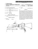
[0012] FIG. 1 is a planar exploded view from the stock end of the rifle.
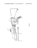
[0013] FIG. 2 is an oblique exploded view from the muzzle end of the rifle.
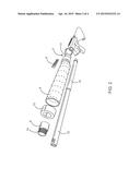
[0014] FIG. 3 is a planar view focusing on the three rings located nearest to the rifle stock.
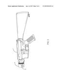
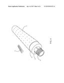
[0015] FIG. 4 is an oblique view of the tube assembly from the muzzle end.
DETAILED DESCRIPTION OF DRAWINGS
[0016] In FIG. 1, a cut away portion of a quad rail 9 (of which there may be alternative styles), is slid over a perforated tube 6. The tube 6 is press fitted over a first ring 5. The first ring 5 has at least two, or in another embodiment, four pre-drilled holes (shown below). If there are only two holes, then they are spaced 180° apart, and if there are four holes, then they are equally spaced 90° apart along the circumference and perpendicular to the longitudinal axis of a rifle barrel 10. A set of the at least two pins (shown below), which are inserted through the perforated tube 6 and into the first ring 5 through the at least two holes (shown below). The pins affix the perforated tube 6 in place.
[0017] The first ring 5 has a two ends, where the end nearest the stock of a rifle 1, is threaded 7. The threaded 7 end meshes with a third ring 2. The second ring 3 is inserted between first ring 3 and the second ring 2. On the end of the second ring nearest the stock of the rifle 1 are threads to affix the second ring 2 to the stock.
[0018] The perforated tube 6 at the end nearest the rifle muzzle 12 is secured by a lock nut adapter (shown below) which has two ends. One end towards the stock of the rifle is keyway connected to a fourth ring (shown below) that is pinned into the aft end of the tube 6. One end of the lock nut adapter is pinned to the rifle barrel 10. The other end of the lock nut adapter is threaded into a lock nut. Thus, a shooter can deploy one or more accessories which are removably attached to each of the rectangular plates of the quad rail by placing the rifle on safe, by unscrewing the rifle stock from the second ring 3 and by unscrewing the fourth ring to disengage the lock nut adapter from the barrel 10, turning the quad rail in either direction until the desired accessory is in position to be used by a shooter, and then re-screwing the rifle stock and the second ring together and re-screwing the fourth ring and lock nut adapter together, then taking the weapon off safe.
[0019] In another embodiment, the at least two pins (shown below) are removable. Rather than unscrew any portion of the weapon, rotation of the quad rail is achieved by removing the at least two pins, turning the quad rail until the desired accessory is available for use, and then reinserting the at least two pins.
[0020] In FIG. 2, the threaded end 14 of the lock nut adapter 8 connects to a lock nut (not shown), where the unthreaded end of the lock nut adapter 8 is pinned to the muzzle end 12 of the rifle barrel 10. The unthreaded end of the lock nut adapter 8 is keyway connected to the fourth ring 13, and pinned into the perforated tube 6. The at least two pins 4 which penetrate the perforated tube 6 and the first ring 5 are depicted. For additional security, in another embodiment, the second ring 3, can also be pinned to the rifle stock 1.
[0021] In FIG. 3, the assembly of the first ring 5, second ring, and third ring, as attached to the rifle stock 1, is shown. Of note in one embodiment, the position of the pre-drilled holes 11 into the first ring 5 which are penetrated by at least two pins (shown above), demonstrates the discrete positions to which the quad rail can be rotated. The second ring spins freely inside the third ring.
[0022] In FIG. 4, the assembly of the lock nut adapter 8, and the fourth ring 13, into the perforated tube 6 is shown. On the end nearest the muzzle, the lock nut adapter 8 is threaded. A cut-away portion of the quad rail 9 is also displayed.
[0023] The above description of the preferred embodiment of the present invention has been presented for the purposes of illustration and description. It is not intended to be exhaustive or to limit the invention to the precise form disclosed. Many modifications and variations are possible in light of the above teachings. It is intended that the scope of the present invention not be limited by this detailed description, but by the claims and the equivalents to the claims.
User Contributions:
Comment about this patent or add new information about this topic:
Images included with this patent application:
 |  |
 |  |
 |
| Similar patent applications: | |
| Date | Title |
|---|---|
| 2015-01-22 | Rail extension device |
| 2015-03-12 | Optical super-elevation device |
| 2015-04-16 | Automated fire control device |
| 2015-04-30 | Realtime memorialization firearm attachment |
| 2015-03-12 | Forward set trigger device |
| New patent applications in this class: | |
| Date | Title |
|---|---|
| 2022-05-05 | Configurable cable holder for firearms |
| 2019-05-16 | Universal gun rail mount for accessories |
| 2018-01-25 | Movable firearm accessory support assembly |
| 2016-12-29 | Rear sight block for ak-type rifles |
| 2016-09-01 | Mounting assembly |
| New patent applications from these inventors: | |
| Date | Title |
|---|---|
| 2015-05-21 | Rifle noise suppressor |
| Top Inventors for class "Firearms" | |
| Rank | Inventor's name |
|---|---|
| 1 | Michael T. Mayberry |
| 2 | Mark C. Laney |
| 3 | Stephen P. Troy |
| 4 | Russell A. Potterfield |
| 5 | Dennis Cauley |