Patent application title: Method and Device for Subsea Sampling
Inventors:
Robert James Cowman (Aberdeen, GB)
Edward John Rafipay (Aberdeen, GB)
Murray George Stuart (Aberdeen, GB)
Craig Andrew Baxter (Aberdeen, GB)
IPC8 Class: AE21B4900FI
USPC Class:
166336
Class name: Wells submerged well testing
Publication date: 2015-03-19
Patent application number: 20150075802
Abstract:
A sampling device is for subsea fluids. The sampling device comprises:
a sample container including a first chamber and a second chamber, the
first and second chambers being isolated by a movable separating body, a
first pressure sensing device for sensing the pressure in the first
chamber of the container, and a second pressure sensing device for
sensing the pressure in the second chamber of the container. The sampling
device further comprises a pressure compensating device, the pressure
compensating device being adapted to compensate for pressure changes in
the first chamber of the container by regulating the pressure in the
second chamber of the container and thereby moving the separating body.
A method is for subsea fluid sampling using a sampling device.Claims:
1. A sampling device for subsea fluids, the sampling device comprising: a
sample container including a first chamber and a second chamber, the
first and second chambers being isolated by a movable separating body; a
first pressure sensing device for sensing the pressure in the first
chamber of the sample container; a second pressure sensing device for
sensing the pressure in the second chamber of the sample container; and a
pressure compensating device, the pressure compensating device being
adapted to compensate for pressure changes in the first chamber of the
sample container by regulating the pressure in the second chamber of the
container and thereby moving the separating body.
2. The sampling device according to claim 1, wherein the pressure compensating device comprises an accumulator.
3. The sampling device according to claim 2, wherein the accumulator is a compressed inert gas accumulator.
4. The sampling device according to claim 2, wherein the accumulator regulates the separating body in the sample container via an actuator cylinder.
5. The sampling device according to claim 1, wherein the pressure compensating device comprises a pump.
6. The sampling device according to claim 1, wherein the pressure compensating device comprises a linear actuator.
7. A method for subsea sampling of fluids by sampling device comprising: a sample container including a first chamber and a second chamber, the first and second chambers being isolated by a movable separating body; a first pressure sensing device for sensing the pressure in the first chamber of the sample container; a second pressure sensing device for sensing the pressure in the second chamber of the sample container; and a pressure compensating device, the pressure compensating device being adapted to compensate for pressure changes in the first chamber of the sample container by regulating the pressure in the second chamber of the container and thereby moving the separating body; the method comprising: collecting a fluid sample in the first chamber of the sample container in a subsea environment; moving the sample container from the subsea environment and to an offshore or on-shore locations; and using a pressure compensating device to compensate for pressure changes in the first chamber of the sample container by regulating the pressure in the second chamber of the sample container and thereby moving the movable separating body.
Description:
[0001] The invention relates to a method for keeping the content of a
sample vessel at an essentially constant pressure. More specifically the
invention relates to a method for maintaining the pressure conditions of
a sample taken subsea while transporting the sample away from the
location where it was taken. The invention also includes a device for
practicing the method.
[0002] Cooling of fluids sampled subsea will cause contraction of the fluid and with the contraction a drop in pressure. The subsequent drop in pressure may lead to gases entrained within the fluid releasing. Once the gases are released they cannot be re-dissolved within the liquid. Therefore precise laboratory analysis cannot take place.
[0003] Devices are known that use pistons to allow evacuation of the sample vessel while keeping the fluid in phase state.
[0004] The object of the invention is to remedy or to reduce at least one of the disadvantages of the prior art, or at least to provide a useful alternative to the prior art.
[0005] The object is achieved by virtue of features disclosed in the following description and in the subsequent claims.
[0006] The overall objective of the invention is to improve the quality of laboratory analysis of fluid samples taken subsea, primarily in the oil- and gas industry. The sample content may be filled onto a sample vessel by a method and a device known per se, for example as described in Norwegian patent application no. 20110774, with the title "Method and device for filling a submerged sample bottle" and filed by the present applicant. By keeping the content of the sample vessel at an essentially constant pressure, where the essentially constant pressure may be essentially equal to or higher than the pressure at the location where the sample was taken, it is possible to maintain the sample in its original fluid state and thereby prevent volatile sample content from vaporizing. The invention thus makes it possible to analyse the subsea samples in their original fluid state in an on-shore or offshore laboratory facility.
[0007] In a first aspect the invention relates to a sampling device for subsea fluids, the sampling device comprising:
[0008] a sample container including a first chamber and a second chamber, the first and second chambers being isolated by a movable separating body;
[0009] a first pressure sensing device for sensing the pressure in the first chamber of the sample container;
[0010] a second pressure sensing device for sensing the pressure in the second chamber of the sample container, wherein the sampling device further comprises a pressure compensating device, the pressure compensating device being adapted to compensate for pressure changes in the first chamber of the sample container by regulating the pressure in the second chamber of the container and thereby moving the separating body.
[0011] By keeping the sample at or above the original sampled pressure, the quality of sample may be maintained. The movable separating body of the sample container may in one embodiment be a piston, floating or connected to a piston rod. In other embodiments the movable separating body may be an elastic diaphragm or a totally enclosed bladder.
[0012] The pressure sensing devices, which may be conventional pressure gauges as known to a person skilled in the art, may sense the pressure directly in the chambers of the sample container, or indirectly in fluids lines or other devices connected to the two chambers.
[0013] In one embodiment the pressure compensating device may comprise an accumulator. The accumulator may be a compressed inert gas accumulator. The inert gas container may be external to the sample container, or the inert gas container may be integral with the sample container.
[0014] The accumulator may be directly connected to the second chamber of the sample container. Alternatively the accumulator may be indirectly connected to the second chamber of the sample container by means of an actuator cylinder. A piston rod of the actuator cylinder may be mechanically connected to a separating movable piston in the sample container.
[0015] In alternative embodiments the pressure compensating device may comprise a pump or a linear actuator, both in fluid communication with the second chamber of the sampling device. The pump may be reversible, and the linear actuator may be mechanic, hydraulic, or pneumatic.
[0016] In a second aspect the invention relates to a method for subsea sampling of fluids by means of a sampling device according to the above description, the method comprising the steps of:
[0017] collecting a fluid sample in the first chamber of the sample container in a subsea environment;
[0018] moving the sample container from the subsea environment and to an offshore or on-shore location, wherein the method further comprises the step:
[0019] by means of a pressure compensating device to compensate for pressure changes in the first chamber of the sample container by regulating the pressure in the second chamber of the sample container and thereby moving the separating body.
[0020] The separating body and the pressure compensating device are used to overcome the large temperature fluctuations seen in the subsea environment, samples can be taken at wellhead pressures which can be in excess of 120° C. The sample container, once removed from the sample point, is exposed to sea bed temperatures close to 0° C.
[0021] Calculations in line with API 521 show the effect of temperature on fluids to have a significant effect on pressure. The pressure compensating device according to the invention will make up any pressure differential due to temperature changes as will be seen in a subsea environment. The pressure compensating device will also act as a safety device if the temperature increases. If the sampling device is in danger of becoming over pressurised by a temperature increase, the pressure compensating device will allow fluid expansion while keeping the pressure within design parameters. Upon the sampling device then cooling the pressure compensating device will then maintain pressure so keeping gases entrained.
[0022] Hereinafter, an example of a non-limiting, preferred embodiment is described and is depicted on the accompanying drawings, where:
[0023] FIG. 1 shows a schematic diagram of a first embodiment of a sampling device according to the present invention;
[0024] FIG. 2 shows a schematic diagram of a second embodiment of a sampling device according to the present invention;
[0025] FIG. 3 shows a schematic diagram of a third embodiment of a sampling device according to the present invention;
[0026] FIG. 4 shows a schematic diagram of a fourth embodiment of a sampling device according to the present invention; and
[0027] FIG. 5 shows a schematic diagram of a fifth embodiment of a sampling device according to the present invention;
[0028] In the following the reference numeral 1 indicates a sampling device according to the present invention. The figures are shown simplified and schematic. Identical reference numerals indicate identical or similar features in the figures.
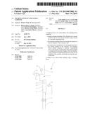
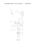
[0029] In FIG. 1 a first sampling device 1 according to the invention is shown. A sample container 11 is divided into a first chamber 111 and a second chamber 113 by means of a sealingly movable separating body 112 in the form a floating piston. A not shown sample is contained in the first chamber 111 of the sample container 11. The not shown sample is collected subsea through sample fluid lines 14a closable by isolation valves 12. The pressure of the sample in the first chamber 111 is measured by a first pressure gauge 13a, while the pressure in the second chamber 113 is measured by a second pressure gauge 13b. The second chamber 113 of the sample container 11 is fluidly connected to a pressurized inert gas accumulator 15. One side of the accumulator 15 contains inert gas supplied via an inert gas line 151 while the other side of the accumulator is fluidly communicating with a hydraulic fluid control line 153. As the collected sample is moved from the subsea environment to an offshore or on-shore laboratory facility, the surrounding temperature will change and thus change the sample pressure. The first pressure gauge 13a, which may be s connected to a not shown control unit, will sense the varying pressure. The accumulator 15, which is fluidly communicating with the second chamber 113 of the sample container 11, will then increase the pressure in the second chamber 113, and thus move the sealingly movable floating piston 112 to compensate for the pressure changes in the first chamber 111, thus maintaining the sample at an essentially constant pressure.
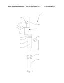
[0030] In FIG. 2 a second sampling device 1 according to the invention is shown. A pressurized inert gas accumulator 15 is is connected to the sample container 11 via an actuator cylinder 16. The accumulator 15 is connected to an inert gas line 151 and to hydraulic control fluid lines 154, 155. The actuator cylinder 16 displaces the piston 112 in the sample container 11 by means of a piston rod 166 common to the actuator cylinder 16 and the sample container 11. The actuator cylinder 16 comprises a first chamber 161 and a second chamber 163 separated by a piston 162 also connected to the piston rod 166. The cylinder actuator 16 is regulated by pressurizing the first chamber 161 through an opening line 165 or the second chamber 163 through a closing line 164. This embodiment of the invention is directly compatible with the previously mentioned Norwegian patent application no. 20110774.
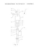
[0031] FIG. 3 shows a third sampling device 1 according to the invention. An accumulator 2 is integral to the sample container 11 in that the second chamber 113 is provided with a pressurized gas cap 19 of inert gases, without any external connections, except from the pressure gauge 13b. Pressure conditions are maintained within the first chamber 111 of the sample container 11 solely by use of the gas cap 19 contained in the second chamber 113 of the sample container 11.
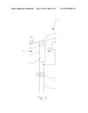
[0032] FIG. 4 shows a fourth sampling device 1 according to the invention. A linear actuator 17, connected to a not shown control unit, is used to simulate the action of an accumulator, thus to regulate the pressure in the sample container 11. The linear actuator 17 may be mechanic, hydraulic, or pneumatic.
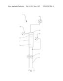
[0033] In FIG. 5 a fifth sampling device 1 according to the invention is shown. A pump 18 is used to simulate the action of an accumulator, thus to regulate the pressure in the sample container 11.
[0034] In general the above mentioned processes may be performed manually or automatically by means of control units communicating with the various components of the embodiments.
[0035] It should also be understood that components of the various embodiments can be combined to provide additional embodiments also within the scope of the present invention.
User Contributions:
Comment about this patent or add new information about this topic:
Images included with this patent application:
 |  |
 |  |
 |  |
| Similar patent applications: | |
| Date | Title |
|---|---|
| 2015-04-16 | Method of treating a downhole formation using a downhole packer |
| 2015-04-16 | Method and system to avoid premature activation of liner hanger |
| 2015-04-16 | Method and apparatus for installing and removing an electric submersible pump |
| 2015-04-16 | Cementing a wellbore using cementing material encaplsulateo in a shell |
| 2015-04-16 | Methods for hanging liner from casing and articles derived therefrom |
| New patent applications in this class: | |
| Date | Title |
|---|---|
| 2016-09-01 | Subsea completion apparatus and method including engageable and disengageable connectors |
| 2016-06-16 | Anti-recoil control design using a hybrid riser tensioning system in deepwater drilling |
| 2016-06-09 | Monitoring tubing related equipment |
| 2016-05-19 | Subsea landing string with autonomous emergency shut-in and disconnect |
| 2016-04-14 | Methods and systems for complex hydraulic fracturing operations and hydrocarbon recovery |
| Top Inventors for class "Wells" | |
| Rank | Inventor's name |
|---|---|
| 1 | Michael L. Fripp |
| 2 | Jean Marc Lopez |
| 3 | Michael H. Johnson |
| 4 | Jørgen Hallundbaek |
| 5 | Dennis P. Nguyen |