Patent application title: METHOD OF OPERATING A HEAT PUMP
Inventors:
Matthias Weiss (Wien, AT)
IPC8 Class: AF25B3002FI
USPC Class:
62115
Class name: Refrigeration processes compressing, condensing and evaporating
Publication date: 2015-03-05
Patent application number: 20150059372
Abstract:
A method of operating a heat pump having an inside heat exchanger, an
outside heat exchanger, a compressor, and valves that control the
circulation of a refrigerant such that in one operating mode the inside
heat exchanger operates as an evaporator while in the other operating
mode it operates as a condenser. When switching from one operating mode
to the other operating mode first the compressor is stopped, then the
inside heat exchanger and the outside heat exchanger are directly
connected via the valves until pressure is equal in both of the heat
exchangers. Subsequently the valves are moved back into the positions
appropriate for the desired operating mode, and the compressor is
restarted.Claims:
1. A method of operating a heat pump having: an inside heat exchanger; an
outside heat exchanger; a compressor; and valves that control the
circulation of a refrigerant such that in one operating mode the inside
heat exchanger operates as an evaporator while in the other operating
mode it operates as a condenser, the method comprising the steps when
switching from one operating mode to the other operating mode of
sequentially: stopping the compressor; directly connecting the inside
heat exchanger and the outside heat exchanger via the valves until
pressure is equal in both of the heat exchangers; moving the valves into
the positions appropriate for the desired operating mode; and restarting
the compressor.
2. The method defined in claim 1, wherein the valves include: a first valve connected between an output of the compressor and the outside heat exchanger; a second valve connected between the intake of the compressor and the inside heat exchanger; a third valve connected between the intake of the compressor and the inside heat exchanger; and a fourth valve connected between the output of the compressor and the inside heat exchanger.
3. The method defined in claim 1, wherein in a cooling mode the first and third valves are open and the second and fourth valves are closed; in a heating mode the first and third valves are closed and the second and fourth valves are open; and the inside and outside heat exchanges are directly connected for pressure equalization by opening the first through fourth valves.
Description:
FIELD OF THE INVENTION
[0001] The present invention relates to a heating-cooling system. More particularly this invention concerns a method operating a heat pump.
BACKGROUND OF THE INVENTION
[0002] A typical heat pump for operation as a building's heating and cooling system has an inside heat exchanger and an outside heat exchanger as well as a compressor and valves that control the circulation of a refrigerant such that in one operating mode the inside heat exchanger operates as an evaporator while in the other operating mode it operates as a condenser.
[0003] Compressors in air conditioners and heat pumps can compress only gaseous refrigerants; they break down if they draw in liquid. In order to protect the compressor, a liquid separator is integrated into the cooling circuit in known equipment so as to ensure that no liquid components are drawn in by the compressor. The requisite inclusion of a liquid separator makes the known units more expensive and also requires costly construction.
OBJECTS OF THE INVENTION
[0004] It is therefore an object of the present invention to provide an improved method of operating a heat pump.
[0005] Another object is the provision of such an improved method of operating a heat pump that overcomes the above-given disadvantages, in particular that renders a liquid separator unnecessary.
SUMMARY OF THE INVENTION
[0006] A method of operating a heat pump having an inside heat exchanger, an outside heat exchanger, a compressor, and valves that control the circulation of a refrigerant such that in one operating mode the inside heat exchanger operates as an evaporator while in the other operating mode it operates as a condenser. When switching from one operating mode to the other operating mode first the compressor is stopped, then the inside heat exchanger and the outside heat exchanger are directly connected via the valves until pressure is equal in both of the heat exchangers. Subsequently the valves are moved back into the positions appropriate for the desired operating mode, and the compressor is restarted.
[0007] In other words, with this invention there is an equalization of pressure during the switch in operating modes. This ensures that, with appropriate dimensioning of the system, all the refrigerant is vaporized and there is no liquid that could get sucked into and damage the compressor
[0008] In the system of this invention two valves are connected upstream of the compressor while two valves are connected downstream of the compressor. Thus, depending on the operating mode, one of the valves can be switched over to the outside heat exchanger while the other can be switched over to the inside heat exchanger.
BRIEF DESCRIPTION OF THE DRAWING
[0009] The above and other objects, features, and advantages will become more readily apparent from the following description, reference being made to the accompanying drawing in which:
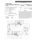
[0010] FIG. 1 is a schematic diagram of a heat pump according to the invention when operating as an air conditioner for cooling;
[0011] FIG. 2 is a schematic diagram of the heat pump when operating diagram of a unit according to the invention when operating as a heater;
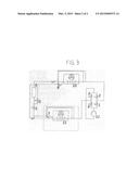
[0012] FIG. 3 is the circuit diagram of a unit according to the invention undergoing pressure equalization.
SPECIFIC DESCRIPTION OF THE INVENTION
[0013] In the drawing, the gaseous state of the refrigerant is indicated by dots while the liquid state of the refrigerant is indicated by wavy waves in the outside and inside heat exchangers. The heat pump has solenoid flow-control (on-off) valves 1-6, expansion valves 7 and 8 with built-in check valves, a storage tank 9, the outside heat exchanger, the inside heat exchanger, and a compressor 12.
[0014] In the cooling mode of FIG. 1, the valves 1, 3 and 5 are held open by their solenoids. The valves 2, 4 and 6 are closed. The compressor 12 compresses gaseous refrigerant that flows under high pressure through the solenoid valve 1 to the outside heat exchanger 10.
[0015] The refrigerant releases its heat to the ambient air in the outside heat exchanger 10 and is thus liquefied. The outside heat exchanger in this operating mode is a condenser.
[0016] While a liquid and under high pressure, the refrigerant then flows through the tank 9 and via the solenoid valve 5 to the expansion valve 7. This expansion valve 7 abruptly lowers the refrigerant's pressure to adiabatically cool it while simultaneously converting it back into vapor. In the inside heat exchanger 11 the refrigerant absorbs heat from the ambient air until the refrigerant is completely converted to vapor. The inside heat exchanger in this operating mode is an evaporator.
[0017] The now once again gaseous refrigerant is drawn in by the compressor 12 via the solenoid valve 3 and again compressed. The cycle starts again.
[0018] In the heating mode, the valves 2, 4 and 6 are held open by their solenoids. The valves 1, 3 and 5 are closed. The compressor 12 compresses the gaseous refrigerant that now flows under high pressure via solenoid valve 4 to the inside heat exchanger 11.
[0019] In this inside heat exchanger 11 the refrigerant releases its heat to the ambient air and is thereby liquefied. The inside heat exchanger in this operating mode is a condenser.
[0020] As a high-pressure liquid, the refrigerant flows through the tank 9 via the solenoid valve 6 to the expansion valve 8 that abruptly lowers the refrigerant's pressure, which not only results cooling the refrigerant, but also converts it back to vapor.
[0021] In the outside heat exchanger 10 the partly vaporized refrigerant absorbs heat from the ambient air until it has vaporized. The outside heat exchanger in this operating mode is an evaporator.
[0022] The now once again gaseous refrigerant is drawn in by the compressor 12 via the solenoid valve 2 and is again compressed. The cycle starts again from the beginning.
[0023] The compressor 12 always takes in only gaseous refrigerant from the respective evaporator both in the heating mode as well as in the cooling mode. The functions of heat exchangers 10 and 11 change when the operating modes are switched in that the evaporator becomes the condenser and vice versa. The problem in switching operating modes results from the fact that, after the switch, the compressor 12 is drawing in from whichever heat exchanger 10 and 11 was previously still operating as a condenser. A certain portion of liquid refrigerant is always in the condenser and would destroy the compressor 12 if it were to reach the compressor. It is critical to ensure that no liquid components from the heat exchanger are drawn in simultaneously.
[0024] Thus the instant invention proposes an equalization of pressure during the switch in operating modes. First the compressor 12 is stopped and all the solenoid valves 1-6 are closed.
[0025] Subsequently the outside heat exchanger 10 and inside heat exchanger 11 are directly connected to each other. This occurs by opening only the solenoid valves 2 and 3. The result is equalization of pressure and temperature between the hot condenser that was previously under high pressure and the cold evaporator that is under low pressure. The components and tubing of the unit must be sized in such a way that the refrigerant after complete equalization is at a temperature-pressure level in which it is in a completely gaseous state.
[0026] Once this state has been reached, the valves 2 and 3 are closed again. Then for cooling the valves 1, 3, and 5 are reopened. For heating valves 2, 4, 6 are reopened.
[0027] Finally the compressor 12 is started.
[0028] The term "valves" used above must not be understood in a narrow meaning. Instead the term is meant to comprise all shutoff elements that serve the desired purpose. Control of the "valves" is effected based on the requirements of the apparatus-internal control unit arising according to the invention.
User Contributions:
Comment about this patent or add new information about this topic:
Images included with this patent application:
 |  |
| Similar patent applications: | |
| Date | Title |
|---|---|
| 2015-04-30 | System and method for enhanced convection cooling of temperature-dependent power producing and power consuming electrical devices |
| 2015-03-26 | Electrocaloric cooler and heat pump |
| 2015-04-30 | Air conditioner and method of controlling the same |
| 2013-06-06 | Alternating type heat pump |
| 2012-09-13 | Extended range heat pump |
| New patent applications in this class: | |
| Date | Title |
|---|---|
| 2022-05-05 | Transport refrigeration system energy management system and method |
| 2019-05-16 | Refrigeration cycle apparatus |
| 2019-05-16 | Speed estimation apparatus for ac motor, driving apparatus for ac motor, refrigerant compressor, and refrigeration cycle apparatus |
| 2018-01-25 | Reversible heat pump with cycle enhancements |
| 2016-09-01 | Air conditioning system and control method thereof |
| New patent applications from these inventors: | |
| Date | Title |
|---|---|
| 2015-11-12 | Heat system for compartment of a train car |
| 2015-11-12 | Heater for the passenger or driver compartment of a train car |
| Top Inventors for class "Refrigeration" | |
| Rank | Inventor's name |
|---|---|
| 1 | Michael F. Taras |
| 2 | Alexander Lifson |
| 3 | Koji Yamashita |
| 4 | Hiroyuki Morimoto |
| 5 | Patrick J. Boarman |