Patent application title: WATER FEEDING DEVICE OF INSTANTANEOUS HEATING TYPE AND CONTROL METHOD THEREOF
Inventors:
Yun-Shan Chang (New Taipei City, TW)
David Lin
IPC8 Class: AF24H920FI
USPC Class:
392465
Class name: Electric resistance heating devices heating devices (class 219 subclass 200) continuous flow type fluid heater
Publication date: 2015-02-19
Patent application number: 20150050012
Abstract:
A water feeding device of instantaneous heating type electrically
connected an external power source includes a water tank, a transparent
pipe, a heating module, a contactless sensing module, and a control
module. The transparent pipe is connected between the water tank and the
heating module. The heating module converts electrical energy of the
external power source to thermal energy. The contactless sensing module
disposed at an outside of the transparent pipe includes a lighting unit
and a light sensing unit. The lighting unit produces a light beam toward
the transparent pipe. The light sensing unit disposed opposite to the
lighting unit detects intensity of the light beam propagating through the
transparent pipe to generate a detection signal accordingly. The control
module electrically connected to the heating module and the contactless
sensing module controls the heating module whether to continuously
produce the thermal energy according to the detection signal.Claims:
1. A water feeding device of instantaneous heating type, electrically
connected to an external power source, comprising: a water tank; a
transparent pipe, one end thereof is connected to the water tank; a
heating module, connected to another one end of the transparent pipe,
used to convert electrical energy of the external power source to thermal
energy, and heat water flow injected from the water tank accordingly; a
contactless sensing module, disposed at an outside of the transparent
pipe, comprising: a lighting unit, used to generate a light beam toward
the transparent pipe; and a light sensing unit, disposed opposite to the
lighting unit, used to detect intensity of the light beam propagating
through the transparent pipe to generate a first detection signal
accordingly; and a control module, electrically connected to the heating
module and the contactless sensing module, used to receive the first
detection signal, and control the heating module whether to continuously
produce the thermal energy according to the first detection signal.
2. The water feeding device of instantaneous heating type according to claim 1, wherein when the light beam propagate through the transparent pipe and the transparent pipe transmits the water flow, due to refraction of the light beam, the intensity of the light beam detected by the light sensing unit is larger than that while the transparent pipe does not transmit the water flow.
3. The water feeding device of instantaneous heating type according to claim 1, wherein the water feeding device of instantaneous heating type further comprises a pump, the pump is connected to the other one end of the transparent pipe, the heating module, and the control module, the pump is controlled by the control module, and determines whether to continuously draw the water flow from the water tank to the heating module according a control signal generated by the control module.
4. The water feeding device of instantaneous heating type according to claim 3, wherein the water feeding device of instantaneous heating type further comprises a water line sensing module, the water line sensing module is disposed in the water tank, electrically connected to the control module, and used to detect a water line of the water flow stored in the water tank to generate a second detection signal accordingly, such that the control module obtains water storage amount of the water tank through the second detection signal; when the water line sensing module detects the water line of the water tank is less than a predetermined threshold, the control module generates the control signal according to the second detection signal, and the control signal is used to indicate the pump to stop drawing the water flow from the water tank.
5. The water feeding device of instantaneous heating type according to claim 4, wherein the water line sensing module comprises: an accommodation tube, a bottom side thereof is connected to the water tank, such that a water line of the accommodation tube varies with the water line of the water tank; a magnetic floating body, disposed in the accommodation tube; and a plurality of Hall sensors, alternately disposed on an outer wall of the accommodation tube, and electrically connected to the control module, wherein the Hall sensors generates the second signal according to a magnet filed variation due to a different position of the magnetic floating body in the accommodation tube.
6. A control method used in a water feeding device of instantaneous heating type, the water feeding device of instantaneous heating type is electrically connected to an external power source, and has a water tank, a transparent pipe, and a heating module, wherein the transparent pipe is disposed between the water tank and the heating module, the heating module is used to converts electrical energy of the external power source to a thermal energy, and the control method comprises: generating a light beam toward the transparent pipe; detecting intensity of the light beam propagating through the transparent pipe, and generating a first detection signal accordingly; and controlling the heating module whether to continuously produce the thermal energy according to the first detection signal.
7. The control method used in the water feeding device of instantaneous heating type according to claim 6, wherein when the light beam propagate through the transparent pipe and the transparent pipe transmits the water flow, due to refraction of the light beam, the intensity of the light beam detected by the light sensing unit is larger than that while the transparent pipe does not transmit the water flow.
8. The control method used in the water feeding device of instantaneous heating type according to claim 6, wherein the water feeding device of instantaneous heating type further comprises a pump, the pump determines whether to continuously draw the water flow from the water tank to the heating module according to a control signal.
9. The control method used in the water feeding device of instantaneous heating type according to claim 8, further comprising: detecting a water line of the water tank to generate a second detection signal accordingly, and when the water line sensing module detects the water line of the water tank is less than a predetermined threshold, controlling the pump to stop drawing the water flow from the water tank to the heating module.
10. The control method used in the water feeding device of instantaneous heating type according to claim 9, wherein to detect the water line of the water tank, a magnetic floating body and a plurality of Hall sensors are used, the magnetic floating body has a different position corresponding to the water line of the water bank, and the Hall sensors are alternately disposed at different positions in the water tank, such that the second detection signal is generated according to the magnet field variation due to a different position of the magnetic floating body.
Description:
BACKGROUND
[0001] 1. Technical Field
[0002] The present disclosure is related to a water feeding device, and in particular to, a water feeding device of instantaneous heating type capable of detecting whether the water line of the water tank is sufficient, and a control method thereof
[0003] 2. Description of Related Art
[0004] Currently, with the development of the human life quality, the requirement for the drinking water in usual life is increasing. The conventional manner for obtaining hot water by heating unboiled water through the gas oven or electric oven is replaced by the manner for obtaining the hot water by using the water dispenser or the thermos, wherein the water dispenser or the thermos can provide the cold and hot water simultaneously.
[0005] However, to meet the requirement that the water dispenser or the thermos must feed water to the user on the go, a heater is used to heat the unboiled water injected into the hot water bile to make the water boiled, and continuously heat the boiled water, such that the temperature of the hot water in the hot water bile can be maintained at a predetermined temperature degree (such as 80 or 100 centigrade degrees).
[0006] Although water dispenser or the thermos provides the convenience for the user to draw the hot water, the unnecessary power is wasted since the hot water in the hot water bile should be maintained the predetermined temperature, and thus the power saving policy dedicated by the government cannot be observed.
[0007] In addition, the usage amount of the hot water required by the user varies with the season or period, for example, the usage amount of the hot water in winter is larger than that in summer. Thus, if the water line of hot water in the hot water bile is maintained the full water line, the power consumption is increased to maintain the temperature of the hot water in the hot bile the specific at the predetermined temperature degree, and thus the practical usage requirement and the efficient usage manner are not met.
SUMMARY
[0008] An exemplary embodiment of the present disclosure provides a water feeding device of instantaneous heating type and a control method thereof, wherein an optical contactless sensing manner is used to detect whether the water tank continuously provides the water flow to the heating module, and when that there not water flow feeding to the heating module is detected, the heating module is turned off, so as to assure the operation safety of the water feeding device of instantaneous heating type.
[0009] An exemplary embodiment of the present disclosure provides a water feeding device of instantaneous heating type. The water feeding device of instantaneous heating type is electrically connected to an external power source, and comprises a water tank, a transparent pipe, a heating module, a contactless sensing module, and a control module, wherein one end of the transparent pipe is connected to the water tank, another one end of the transparent pipe is connected to the heating module, and the contactless sensing module is disposed at an outer side of the transparent pipe. The heating module converts electrical energy of the external power source to thermal energy, so as to heat the water flow injected from the water tank. The contactless sensing module comprises a lighting unit and a light sensing unit, wherein the light sensing unit is disposed opposite to the lighting unit. The lighting unit is used to generate a light beam toward the transparent pipe, and the light sensing unit is used to detect intensity of the light beam propagating through the transparent pipe to generate a first detection signal accordingly. The control module is electrically connected the heating module and the contactless sensing module, receives the first detection signal, and controls the heating module whether to continuous produce the thermal energy according to the first detection signal.
[0010] An exemplary embodiment of the present disclosure provides a control method used in a water feeding device of instantaneous heating type, the water feeding device of instantaneous heating type is electrically connected to an external power source, and has a water tank, a transparent pipe, and a heating module, wherein the transparent pipe is disposed between the water tank and the heating module, the heating module is used to converts electrical energy of the external power source to a thermal energy. The control method comprises steps of: generating a light beam toward the transparent pipe; detecting intensity of the light beam propagating through the transparent pipe, and generating a first detection signal accordingly; and controlling the heating module whether to continuously produce the thermal energy according to the first detection signal.
[0011] To sum up, the exemplary embodiments of the present disclosure provide a water feeding device of instantaneous heating type and control method thereof. Since the refraction indices of the water and air different from each other, the water feeding device of instantaneous heating type uses a contactless sensing module disposed at an outside of the transparent pipe connected between the water tank and the heating module to detect whether the water flow continuously flows into the heating module. When that the water flow does not flow into the heating module is detected, the heating module is turned off and stop generating the thermal energy.
[0012] In order to further understand the techniques, means and effects of the present disclosure, the following detailed descriptions and appended drawings are hereby referred, such that, through which, the purposes, features and aspects of the present disclosure can be thoroughly and concretely appreciated; however, the appended drawings are merely provided for reference and illustration, without any intention to be used for limiting the present disclosure.
BRIEF DESCRIPTION OF THE DRAWINGS
[0013] The accompanying drawings are included to provide a further understanding of the present disclosure, and are incorporated in and constitute a part of this specification. The drawings illustrate exemplary embodiments of the present disclosure and, together with the description, serve to explain the principles of the present disclosure.
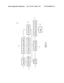
[0014] FIG. 1 is a function block diagram of a water feeding device of instantaneous heating type according to one exemplary embodiment of the present disclosure.
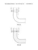
[0015] FIG. 2A is a lateral view showing practical operation of the contactless sensing module according to one exemplary embodiment of the present disclosure.
[0016] FIG. 2B is a lateral view showing practical operation of the contactless sensing module according to another one exemplary embodiment of the present disclosure.
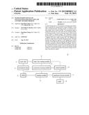
[0017] FIG. 3 is a function block diagram of a water feeding device of instantaneous heating type according to another one exemplary embodiment of the present disclosure.
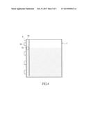
[0018] FIG. 4 is a lateral view showing a water line sensing module and a water tank according to one exemplary embodiment of the present disclosure.
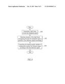
[0019] FIG. 5 is a flow chart of a control method used in the water feeding device of instantaneous heating type according to one exemplary embodiment of the present disclosure.
DESCRIPTION OF THE EXEMPLARY EMBODIMENTS
[0020] Reference will now be made in detail to the exemplary embodiments of the present disclosure, examples of which are illustrated in the accompanying drawings. Wherever possible, the same reference numbers are used in the drawings and the description to refer to the same or similar parts.
[0021] [Exemplary Embodiment of Water Feeding Device of Instantaneous Heating Type]
[0022] Referring to FIG. 1, FIG. 1 is a function block diagram of a water feeding device of instantaneous heating type according to one exemplary embodiment of the present disclosure. As shown in FIG. 1, the water feeding device of instantaneous heating type A comprises a water tank 1, a pump 2, a transparent pipe 3, a heating module 4, a contactless sensing module 5, and a control module 6, a gas/liquid mixing module 7, and an outlet 8, wherein the transparent pipe 3 is connected between the water tank 1 and the pump 2, the contactless sensing module 5 is correspondingly disposed at an outside of the transparent pipe 3. In addition, the pump 2 is connected to the heating module 4, the gas/liquid mixing module 7, and the outlet 8, and the pump 2, the heating module 4, and the contactless sensing module 5 are electrically connected to the control module 6. In practical operation, the water feeding device of instantaneous heating type A should be electrically connected to an external power source (not shown in the drawings), such that the water feeding device of instantaneous heating type A can operate normally. However, that the external power source is a power source of a direct current (DC) or alternative current (AC) type is not used to limit the present disclosure. Each function module of the water feeding device of instantaneous heating type A is depicted with the following detailed descriptions.
[0023] The water tank 1 is detachably installed on the upper side of the water feeding device of instantaneous heating type A and connected to one end of the transparent pipe 3. The water tank 1 is used to stores the liquid to be heated by the water feeding device of instantaneous heating type A. The water storage amount of the water tank 1 is not used to limit the present disclosure. In addition, the radius and shape of the transparent pipe 3 are not limited, for example the transparent pipe 3 can be a rectangular pipe, a spiral pipe, or an irregular curved pipe.
[0024] The pump 2 is connected to another one end of the transparent pipe 3, and used to draw the water flow stored in the water tank 1 to the heating module 4. In the exemplary embodiment, the pump 2 is controlled by the control module 6, and determines whether to continuously draw the water flow from the water tank 1 to the heating module 14 according to a first control signal generated by the control module 6. Practically, the pump 3 can be a volumetric pump, a kinetic pump, or an electromagnetic pump, and the type of the pump 3 is not used to limit the present disclosure.
[0025] The heating module 4 is connected to the transparent pipe 3 through the pump 2, and used to convert electrical energy of the external power source to thermal energy, so as to heat the water flow injected from the water tank 1. Practically, the heating module 4 is usually formed by a block structure and a plate structure, wherein the block structure is used to make the water flow generate turbulence, and the plate structure is used to heat the water flow flows thereon. However, the present disclosure is not limited by the practical structure of the heating module 4 and the material of the above structure.
[0026] Please refer to FIG. 2A and FIG. 2B, the disposed position and the operation of the contactless sensing module 5 are depicted in details, wherein FIG. 2A is a lateral view showing practical operation of the contactless sensing module according to one exemplary embodiment of the present disclosure, and FIG. 2B is a lateral view showing practical operation of the contactless sensing module according to another one exemplary embodiment of the present disclosure. As shown in FIG. 2A and FIG. 2B, the contactless sensing module 5 is disposed at an outside of the transparent pipe 3, and used to detect whether the transparent pipe 3 transmits the water flow to the heating module 4. To put it concretely, the contactless sensing module 5 comprises a lighting unit 50 and a light sensing unit 52, wherein the lighting unit 50 is disposed at an arbitrary position of the outside of the transparent pipe 3, and the light sensing unit 52 is disposed opposite to the disposed position of the lighting unit 50, such that the connection lime of the lighting unit 50 and the light sensing unit 52 passes through the central axis of the transparent pipe 3.
[0027] The lighting unit 50 is used to generate a light beam L toward the transparent pipe 3. Practically, the lighting unit 50 can be a light emitting diode (LED), a laser diode (LD), or an organic light emitting diode (OLED), and the present disclosure is not limited thereto. Thus, the type of the light beam L generated by the lighting unit 50 does not limit the present disclosure, for example, the light beam can be a infrared light, a ultraviolet ray, a visible light with any color, or a laser beam.
[0028] The light sensing unit 52 is used to detect intensity of the light beam propagating through the transparent pipe 3 to generate a first detection signal accordingly. Practically, the light sensing unit 52 can be a photodiode, a photoresistor, a charge coupled device (CCD), a color sensor, or an ambient light sensor (ALS), and the present disclosure is not limited thereto.
[0029] In practical operation, since the refraction indices of the air and water are different from each other, such that when the light beam L generated by the lighting unit 50 propagates through the transparent pipe 3, a refraction phenomenon may thus happen. As shown in FIG. 2A, the transparent pipe 3 does not transmit the water flow drawn from the water tank 1, that is, the interior and the exterior of the transparent pipe 3 are surrounded by the air. Thus, when the light beam L propagates through the transparent pipe 3 to be detected by the light sensing unit 52, since the medium of the interior and the exterior of the transparent pipe 3 are air, the refraction phenomenon of the light beam L does not happen. Furthermore, since the light beam L of any type would have gradual scattering property (p.s. the light beams L of different types have different scatter levels) during propagation, the energy of the light beam L is gradually dispersed, such that the light sensing unit 52 merely detects little portion energy of the light beam L.
[0030] As shown in FIG. 2B, the transparent pipe 3 transmits the water flow drawn from the water tank 1, that is, the interior of the transparent pipe 3 is full of the water flow, and the exterior of the transparent pipe 3 is surrounded by the air. Thus, when the light beam L propagates through the transparent pipe 3 to be detected by the light sensing unit 52, based on Snell's law, the refraction phenomenon of the light beam L will happen, since the light beam L propagates to another medium (such as water flow) with different refraction index from the original medium (such as air). In the exemplary embodiment, since the light beam L sequentially propagates through the air, the water flow, and the air, refraction phenomenon of the light beam happens twice. To put it concretely, when the light beam L propagates from the air to the transparent pipe 3 full of the water flow, since the refraction index of the water (about 1.33) is larger than the refraction index of the air (about 1), based on the Snell's law, between the interface of the air and the water, the incident angle of the light beam L in the air is larger than the refraction angle of the light beam L in the water, such that the energy of the light beam L propagating in the water is more condensed the energy of the light beam L propagating in the air, and the light sensing unit 52 detects much portion energy of the light beam L. In other words, when the light beam L propagates through the transparent pipe 3, and the transparent pipe 3 transmits the water flow, owing to the refraction phenomenon of the light beam L, the intensity of the light beam L detected by the light sensing unit 52 is larger than the intensity of the light beam L detected by the light sensing unit 52 when the transparent pipe 3 does not transmits the water flow.
[0031] The control module 6 receives the first detection signal, and controls the heating module 4 whether to continuously produce the thermal energy according to the first detection signal. To put it concretely, after the control module 6 receives the first detection signal indicating that the transparent pipe 3 does not transmit the water flow, the control module 6 generates a second control signal according to according to the first detection signal, and transmits the second control signal to the heating module 4. Thus, the heating module 4 determines whether to continue to produce thermal energy or stop producing the thermal energy according to the second control signal, so as to prevent possible damage and danger caused by that the heating module 4 continuously heats while no water flow flows therein. Practically, the control module 6 can be a microcontroller unit (MCU), a central processor unit (CPU), or at least one of a software or hardware for storing control commands and for controlling each function modules of the present disclosure, and the present disclosure is not limited thereto.
[0032] The gas/liquid mixing module 7 is used to convert the fluid (comprising the hot water flow and water steam) output from the water outputting end of the heating module 4 to the liquid hot water flow, so as to prevent from the spreading of the water steam, and to increase the thermal energy conversion efficiency. Practically, the gas/liquid mixing module 7 is a thin and long tube, and the present disclosure is not limited thereto. The outlet 9 is for example a water feeding valve.
[0033] In addition, the water feeding device of instantaneous heating type A can further comprises an input module (not shown in the drawings), and the input module is electrically connected to the control module 6. The input module provides the user to manually set the output amount of the water flow output by the water feeding device of instantaneous heating type A (i.e. the amount of the water flow drawn from the water tank 1 by the pump 2), and to manually set the temperature of the output water flow (i.e. the thermal energy produced by the heating module 4). Practically, the input module can be a knob, a push button, a dip switch, or a touch control display panel, and the present disclosure is not limited thereto.
[0034] [Another One Exemplary Embodiment of Water Feeding Device of Instantaneous Heating Type]
[0035] Referring to FIG. 3, FIG. 3 is a function block diagram of a water feeding device of instantaneous heating type according to another one exemplary embodiment of the present disclosure. As shown in FIG. 3, the water feeding device of instantaneous heating type A' comprises a water tank 1, a pump 2, a transparent pipe 3, a heating module 4, a contactless sensing module 5, a control module 6, a gas/liquid mixing module 7, an outlet 8, and a water line sensing module 9. Since the most function modules of the water feeding device of instantaneous heating type A' are the same as those of the water feeding device of instantaneous heating type A, operations and connections of the same function modules are not described again in the exemplary embodiment.
[0036] Being different from the water feeding device of instantaneous heating type A of the previous exemplary embodiment, the water feeding device of instantaneous heating type A' in the exemplary embodiment further comprises the water line sensing module 9. The water line sensing module 9 is disposed corresponding to the water tank 1 and electrically connected to the control module 6. The water line sensing module 9 detects the water line of the water flow stored in the water tank 1, and generates a second detection signal accordingly. The control module 6 obtains the water storage amount of the water tank 1 according to the second detection signal. In practical operation, when the water line sensing module 9 detects the water line of the water tank 1 is less than a predetermined threshold, the control module 6 generates the first control signal according to the second detection signal to the pump 2, so as to indicate the pump 2 to stop drawing the water flow from the water tank 1, and to notice the user refills the water-flow to the water tank 1, or to notice the water feeding device of instantaneous heating type A' to automatically refill the water flow of the water tank 1. In addition, the predetermined threshold can be preset before the manufacturer provides the water feeding device of instantaneous heating type A', or set by the user requirement, and the present disclosure is not limited thereto.
[0037] Please refer to FIG. 4, the disposed position and the operation of the water line sensing module 9 are depicted in details, wherein FIG. 4 is a lateral view showing a water line sensing module and a water tank according to one exemplary embodiment of the present disclosure. As shown in FIG. 4, the water line sensing module 9 comprises an accommodation tube 90, a magnetic floating body 92, and a plurality of Hall sensors 94. The bottom side of the accommodation tube 90 is connected to the water tank 1, such that the water line of the accommodation tube 90 varies with the water line of the water tank 1; that is, when the water line of the water tank 1 is dropped, the water line of the accommodation tube 90 is dropped, too. The magnetic floating body 92 is disposed in the accommodation tube 90, and the position of the magnetic floating body 92 in accommodation tube 90 varies with the rising/dropping of the water line of the accommodation tube 90. The present disclosure does not limit the radius of the material of the accommodation tube 90 and the outline shape of the magnetic floating body 92.
[0038] The Hall sensors 94 are alternately disposed on an outer wall of the accommodation tube 90 and electrically connected to the control module 6. In practical operation, the Hall sensors 94 generate the second control signal according to a magnet filed variation due to a different position of the magnetic floating body 92 in the accommodation tube. That is, when the water line of the water tank 1 changes, since the position of the magnetic floating body 92 in the accommodation tube 90 changes with the change of the water line of accommodation tube 90, the magnet filed changes. Thus, the Hall sensors 94 can detect the water line of the water tank 1 according to the magnet filed variation, and transmit the generated second detection signal to the control module 6, and the control module 6 can determine whether to continuously draw the water flow from the water tank 1. In addition, the present disclosure does not limit the number and spacing distance of the Hall sensors 94. The person with ordinary skill in the art may design a reasonable number and spacing distance of the Hall sensors 94 according to the practical usage condition.
[0039] [Exemplary Embodiment of Control Method Used in Water Feeding Device of Instantaneous Heating Type]
[0040] Referring to FIG. 3 and FIG. 5, FIG. 5 is a flow chart of a control method used in the water feeding device of instantaneous heating type according to one exemplary embodiment of the present disclosure. The water feeding device of instantaneous heating type A' should be electrically connected to the external power source (not shown in the drawings), and has the water tank 1, the transparent pipe 3, and the heating module 4, wherein the transparent pipe 3 is disposed between the water tank 1 and the heating module 4, and the heating module 4 is used to convert the electrical energy of the external power source to the thermal energy.
[0041] As shown in FIG. 5, at step S50, the water feeding device of instantaneous heating type A' generates a light beam toward the transparent pipe 3. Next, at step S52, the water feeding device of instantaneous heating type A' detects intensity of the light beam propagating through the transparent pipe 3 to generate a first detection signal accordingly, wherein the when the light beam propagates the transparent pipe 3 and the transparent pipe 3 transmits the water flow, due to the refraction of the light beam, the intensity of the detected light beam is larger than the intensity of the detected light beam when the transparent pipe 3 does not transmit the water flow. Finally, at step S54, the water feeding device of instantaneous heating type A' controls the heating module 4 whether to continuously produce the thermal energy according to the first detection signal.
[0042] It is preferred that the water feeding device of instantaneous heating type A' further comprises the pump 2, and the pump 2 determines whether to draw the water flow from the water tank 1 to the heating module 14 according to the first control signal.
[0043] Then, the water feeding device of instantaneous heating type A' may detect the water line of the water flow stored in the water tank 1, and generate the second detection signal accordingly. When that the water line of the water tank 1 is less than a predetermined threshold is detected, the water feeding device of instantaneous heating type A' further controls the pump 2 to stop drawing the water flow from the water tank 1 to the heating module 4.
[0044] Next, a magnetic floating body and a plurality of Hall sensors are used to detect the water line of the water tank 1. The magnetic floating body has the different position corresponding to the water line of the water bank 1, and the Hall sensors are alternately disposed at different positions in the water tank 1, such that the second detection signal is generated according to the magnet field variation due to a different position of the magnetic floating body.
[0045] [Possible Result of Exemplary Embodiment]
[0046] Accordingly, the exemplary embodiments of the present disclosure provide a water feeding device of instantaneous heating type and control method thereof. Since the refraction indices of the water and air different from each other, the water feeding device of instantaneous heating type uses a contactless sensing module disposed at an outside of the transparent pipe connected between the water tank and the heating module to detect whether the water flow continuously flows into the heating module. When that the water flow does not flow into the heating module is detected, the heating module is turned off and stop generating the thermal energy. In addition, the water feeding device of instantaneous heating type further uses a water line sensing module to detect whether the water line of the water tank is sufficient. When that the water line of the water tank is less than the predetermined threshold is detected, the pump is controlled to stop drawing the water flow from the water bank. Therefore, the water feeding device of instantaneous heating type and the control method thereof use the contactless sensing module and the water line sensing module to control the heating module and the pump to operate efficiently, so as to prevent the damage of the heating module and the possible danger. That is, the water feeding device of instantaneous heating type and the control method has the safety and practicality.
[0047] The above-mentioned descriptions represent merely the exemplary embodiment of the present disclosure, without any intention to limit the scope of the present disclosure thereto. Various equivalent changes, alternations or modifications based on the claims of present disclosure are all consequently viewed as being embraced by the scope of the present disclosure.
User Contributions:
Comment about this patent or add new information about this topic:
Images included with this patent application:
 |  |
 |  |
 |  |
| New patent applications in this class: | |
| Date | Title |
|---|---|
| 2016-02-04 | Heating device |
| 2015-03-12 | Device for electrically heating fluid for a motor vehicle, and related heating and/or air-conditioning apparatus |
| 2015-03-12 | Instantaneously heating water dispenser and control method thereof |
| 2015-02-12 | Electrical heating device for a motor vehicle, and associated heating, ventilation and/or air conditioning apparatus |
| 2014-10-30 | Liquid heater with temperature control |
| New patent applications from these inventors: | |
| Date | Title |
|---|---|
| 2013-08-08 | Agent delivery system capable of selectively releasing an agent |
| Top Inventors for class "Electric resistance heating devices" | |
| Rank | Inventor's name |
|---|---|
| 1 | Joseph M. Ranish |
| 2 | Alexander Dauth |
| 3 | Jeff Hankins |
| 4 | David Kreutzman |
| 5 | Khurshed Sorabji |