Patent application title: MODULAR ASSEMBLY FOR COVERING A FLOOR
Inventors:
Frederic Bernat (Ivry Sur Seine, FR)
Frederic Bien (Ivry Sur Seine, FR)
Assignees:
F.G.I. SAS
IPC8 Class: AE04F1502FI
USPC Class:
525881
Class name: Static structures (e.g., buildings) module or panel having discrete edgewise or face-to-face connecting feature interfitted integral flange
Publication date: 2015-02-19
Patent application number: 20150047286
Abstract:
The invention relates to an assembly comprising a series of unitary
support modules (10) that arc assembled to one another to form a lower
flat support that can be inserted vertically between the floor and a
modular upper cover comprising a series of cover elements (102) which are
affixed to the upper surfaces (12) of the unitary support modules (10).
The assembly is characterised in that each modular cover element (102) is
affixed to the tipper surfaces of the unitary support modules (10) using
securing means (118, 50) having co-operating complementary shapes and by
means o f a vertical elastic interlocking arrangement.Claims:
1. An assembly for producing a floor coating of the type comprising: a
lower modular support structure (100) which comprises a series of unitary
support modules (10) whereof each is a plate of polygonal contour which
is delimited by a flat horizontal upper face (12) and which are assembled
together to constitute a flat support capable of being interposed
vertically between the ground and an upper coating; a modular upper
coating which comprises a series of adjacent modular coating elements
(102), such as slabs or boards, which are fixed on the upper faces (12)
opposite said unitary support modules (10), characterized in that each
modular coating element (102) is fixed on the upper faces of said unitary
support modules (10) by fastening means (118, 50) cooperating with
complementary forms and by snap fitting according to the vertical
direction (V).
2. The assembly according to the previous claim, characterized in that said fastening means (118) comprise: at least one section of fixing rail which is formed on the lower face (106) of each modular coating element (102) and which delimits two opposite longitudinal hooking grooves (120); a series of elastically deformable hooks (50) which are formed on the upper face (12) of each modular support element (10) and which are arranged by pairs of opposite hooks, said pairs of hooks (50) being aligned longitudinally and arranged such that the two opposite hooks of a pair of hooks (50) are received respectively in the two opposite grooves (120) of a fixing rail (118) when the modular coating element (102) is fixed on the upper faces (12) opposite said unitary support modules (10).
3. The assembly according to the previous claim, characterized in that, in section via a transversal vertical plane, each fixing rail (118) has a dovetail profile.
4. The assembly according to claim 2, characterized in that the lower face (106) of each modular coating element (102) is fitted with a series of parallel fixing rails (118) which are arranged according to a regular transversal pitch, and in that the upper face (12) of each modular support element (10) comprises several parallel series of pairs of hooks (50) aligned longitudinally and which are arranged according to the same regular transversal pitch.
5. The assembly according to any one of claims 2 to 4, characterized in that each section of fixing rail (118) extends over the entire length of the modular coating element (102).
6. The assembly according to any one of the previous claims, characterized in that the upper face of each unitary support module (10) is fitted with a series of positioning pins (60) which are formed in relief and which cooperate with associated positioning ribs (110, 116) protruding below the lower face (106) of the modular coating elements opposite.
7. The assembly according to any one of claims 2 to 6, characterized in that each modular coating element (102) has a regular polygonal contour, especially rectangular, and in that each section of fixing rail (118) extends parallel to the length of its contour.
8. The assembly according to the previous claim, characterized in that the greatest length of each modular coating element (102) is greater than the greatest length of a modular support element.
9. The assembly according to any one of the previous claims, characterized in that each support module and/or each modular coating element is made in a single moulded piece, especially of plastic material.
Description:
FIELD OF THE INVENTION
[0001] The invention relates to an assembly for producing a floor coating.
[0002] The invention relates especially to a complement of the modular support structure of a floor coating described and illustrated in document FR-A-2.955.601.
[0003] This document describes and illustrates a modular support structure of a floor coating which comprises a series of adjacent modular coating elements such as slabs or boards which are fixed on the upper face of a lower flat support interposed between the modular elements constituting a floor and the ground.
[0004] This document proposes fixing the series of modular elements constituting the floor coating per se by fixing elements such as screws or nails which are received in studs belonging to the plates constituting the lower modular support structure of the floor, interposed between the ground and the floor.
[0005] The invention relates to an assembly for producing a floor coating of the type comprising:
[0006] a lower modular support structure which comprises a series of unitary support modules whereof each is a plate of polygonal contour which is delimited by a flat upper horizontal face and which are assembled together to constitute a flat support capable of being interposed vertically between the ground and an upper coating;
[0007] a modular upper coating which comprises a series of adjacent modular coating elements, such as slabs or boards which are fixed on the upper faces opposite said unitary support modules.
[0008] The aim of the invention is to propose novel fastening means of modular coating elements which for mounting, assembly and fixing do not need nails of screws.
SUMMARY OF THE INVENTION
[0009] For this purpose, the invention proposes an assembly of the type mentioned hereinabove, characterized in that each modular coating element is fixed on the upper faces of said unitary support modules by fastening means cooperating with complementary forms and by snap fitting according to the vertical direction.
[0010] Because of this design, the positioning, assembly and placing of the modular coating elements, such as slabs or boards, are done by simple snap fitting, that is, without use of any fixing particular tool such as for example a screwdriver and screws.
[0011] According to other characteristics of the invention:
[0012] the fastening means comprise:
[0013] at least one section of fixing rail which is formed on the lower face of each modular coating element and which delimits two opposite longitudinal hooking grooves,
[0014] a series of elastically deformable hooks formed on the upper face of each modular support element and which are arranged by pairs of opposite hooks, said pairs of hooks being aligned longitudinally and arranged such that the two opposite hooks of a pair are received respectively in the two opposite grooves of a fixing rail when the modular coating element is fixed on the upper faces opposite said unitary support modules,
[0015] in section by a transversal vertical plane, each guide rail has a dovetail profile;
[0016] the lower face of each modular coating element is fitted with a series of parallel fixing rails which are arranged according to a regular transversal pitch, and the upper face of each modular support element comprises several parallel series of pairs of hooks aligned longitudinally and which are arranged according to the same regular transversal pitch;
[0017] each section of fixing rail extends over the entire length of the modular coating element;
[0018] the upper face of each unitary support module is fitted with a series of positioning pins which are formed in relief and which cooperate with associated positioning ribs protruding below the lower face of the opposite modular coating elements;
[0019] each modular coating element has a regular polygonal contour, especially rectangular, and each section of fixing rail extends parallel to the length of its contour;
[0020] the greatest length of each modular coating element is greater than the greatest length of a modular support element;
[0021] each support module and/or each modular coating element is made in a single moulded piece, especially of plastic material.
BRIEF DESCRIPTION OF DIAGRAMS
[0022] Other characteristics and advantages of the invention will emerge from the following detailed description for comprehension of which reference is made to the appended drawings, in which:
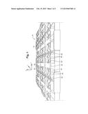
[0023] FIG. 1 is a perspective plan view of a plate belonging to the lower modular support structure;
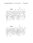
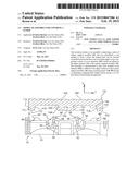
[0024] FIG. 2 is a sectional view through a vertical transversal plane illustrating opposite a lower plate and an upper modular element with their complementary assembly means, and which are illustrated in a relative position prior to assembly;
[0025] FIG. 3 is a view similar to that of FIG. 2 in which the two elements are in the assembled position; and
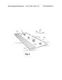
[0026] FIG. 4 is a schematic perspective view of an assembly according to an embodiment of the invention.
DETAILED DESCRIPTION OF AN EMBODIMENT
[0027] In the following description identical or similar elements will be designated by the same reference numerals.
[0028] For easier comprehension of the description and claims, the terms vertical, horizontal, longitudinal, transversal will be used as non-limiting in reference to terrestrial gravity and the trihedron L, V, T illustrated in the figures.
[0029] The lower modular support structure 100 is of the type of that described in document FR-A-2.955.601.
[0030] This lower structure 100 comprises a series of unitary modules 10 for making the lower modular support structure by assembly of several of these modules 10.
[0031] Each module 10 is a plate of square contour whereof the general plane is horizontal in use, that is, parallel to the ground on which it will be placed.
[0032] Each plate 10 is delimited by a horizontal flat upper face 12 and by an opposite horizontal flat lower face 14 designed to rest on the ground.
[0033] The assembly of the horizontal flat upper faces 12 of the plates 10 constitutes the flat horizontal upper face 12 of the lower modular support structure in terms of the invention.
[0034] The assembly of the unitary modules 10 constitutes a flat support, with a horizontal flat upper face 12, which is capable of being interposed vertically between the ground and the upper coating constituting the floor.
[0035] By way of non-limiting example, each modular element 102 of the upper coating is a slab or board of rectangular contour whereof the greatest length extends according to the longitudinal direction L.
[0036] Each element 102 is in the form of a board whereof the upper face 104 is grooved longitudinally by grooves 105.
[0037] The board 102 is of greater dimension than a modular element 10, according to its length, and extends especially over a length such that it covers longitudinally and simultaneously several adjacent lower unitary modules 10 (see FIG. 4).
[0038] Each board 102 is delimited by a lower horizontal face 106 from which two opposite lateral ribs 110 formed in the extension of the lateral edges 108 of the board 102 extend on either side.
[0039] Each rib 110 is delimited externally by a vertical lateral face 114 in the extension of the edge 108 then by a lower horizontal face 112 capable of being supported on the horizontal upper face 12 of the lower modules 10, in assembled and fixed position of the board 12 on the lower modular structure.
[0040] Finally, each lateral rib 110 is delimited internally by an inclined longitudinal face 116 whereof the function will be explained hereinbelow.
[0041] Centrally, that is, substantially at mid-distance 5 between the two ribs 110, the board 102 comprises a central fixing rail 118.
[0042] The rail 118, in section via a transversal vertical plane, and as is evident especially in FIGS. 2 and 3, has a dovetail profile which delimits especially two opposite lateral grooves 120.
[0043] The fixing rail 118 is also delimited by a lower flat face 122 which is coplanar with the lower faces 112 of the ribs 110 and which, in assembled position of the board 102 on the modular structure 100 is supported vertically on the upper face 12 of the modular elements 10.
[0044] The support vertically downwards of a board or slab 102 by means of the longitudinal and horizontal flat faces 112 and 122 produces excellent support stability on the horizontal upper face 12 of the lower modular structure.
[0045] The horizontal lower longitudinal face 122 of the fixing rail 118 is connected on either side to each of the opposite longitudinal grooves 120 by an inclined longitudinal facet 124 forming a bevel whereof the function will be explained hereinbelow.
[0046] The lateral ribs 110 and the central fixing rail 118 here extend, by way of non-limiting example, over the entire length of the board 102 which is in the form of a profile of transversal section of continuous profile according to the length L.
[0047] By way of non-limiting example, the transversal width of a board 102 is such that its lower face comprises just one fixing rail 118, but without departing from the scope of the invention the board could comprise several parallel fixing rails distributed transversally according to a defined pitch below the lower face 106.
[0048] The fixing rail 118 constitutes one of the fixing complementary means, by complementary forms and snap fitting, of the slab or board 102 on the lower modular structure 100 constituted by the assembly of the lower modules 10.
[0049] For this purpose, the complementary means of the lower modular structure 100 here comprise a series of elastically deformable hooks formed on the upper face 12 of each modular support element 10.
[0050] More precisely, each modular support element 10 comprises several series of pairs of opposite hooks 50 which extend vertically projecting above the horizontal face 12.
[0051] Each hook 50 is in the form of an elastically deformable blade 52 which extends overall according to the vertical direction and longitudinally and which comprises at its upper free end a rib 56 forming a hook respectively and whereof each is capable of being received in a complementary groove 120, in the assembled position.
[0052] The blades 52 with their ribs 56 forming a hook are elastically deformable so as to constitute a pair of elastically deformable hooks, their elastic deformation produced by the cooperation of the inclined facets 124 of a rail 118 with the bevelled upper faces 58 of the hooks 56, during the snap fitting produced by pressure according to the vertical direction and introduction of a rail 118 between the pairs of hooks 50 aligned longitudinally.
[0053] So that the hooks 50 are not too fragile, each blade 52 is connected to the structure of a module 10 by a transversal and vertical reinforcing groove 54.
[0054] The relative sizing and positioning of two hooks 50 of a pair of hooks is of course complementary to the width of a fixing rail 118 with its two opposite throats 120.
[0055] As is evident in FIG. 1, each upper face 12 comprises several series of pairs of hooks 50 aligned longitudinally, these series being arranged according to a transversal pitch such that a module 10 can receive either a slab or a board 102 comprising several parallel fixing rails arranged according to the same transversal pitch, either several slabs or adjacent boards whereof the dimensions and positioning of the fixing rails are such that two parallel fixing rails 118 each belonging to one of two adjacent boards 102 is received in a series of pairs of hooks aligned longitudinally.
[0056] Also, for easier positioning and keeping the boards 102 on the lower modular structure 100 in the position assembled, the upper face of each unitary module support 10 is fitted with a series of positioning pins 60 which are formed in relief above the horizontal upper face 12.
[0057] Each pin 60 is delimited laterally by an inclined external lateral face 62 whereof the slope is complementary to that of each inclined inner lateral face 116 of a rib 110 of a board or slab 102.
[0058] So, as is evident from FIG. 3, when in assembled position the opposite pins 60 cooperate by their inclined external lateral faces 62 with the opposite inner inclined faces 116 of the ribs 110.
[0059] Therefore, all the assembly and precise positioning of the floor coating constituted by the upper adjacent modular elements 102 can be done by simple positioning and snap fitting, that is, without use of any particular tool.
[0060] If necessary, and in addition, and as indicated in document FR-A-2.955.601, fixing after positioning and assembly can be completed for this purpose by screws or nails received in the studs 30 of the lower 10 plates 5 and in the core of the material constituting a fixing rail 118, the studs 30, for this purpose being arranged centrally between the pairs of opposite hooks 50, that is, opposite the lower face 122 of a fixing rail 118.
User Contributions:
Comment about this patent or add new information about this topic:
Images included with this patent application:
 |  |
 |  |
| New patent applications in this class: | |
| Date | Title |
|---|---|
| 2022-05-05 | Panel and covering comprising the same |
| 2018-01-25 | System and method for interlocking structural members |
| 2016-09-01 | Floor covering, floor element and method for manufacturing floor elements |
| 2016-07-14 | Method for producing a directly printed panel |
| 2016-07-07 | Board material structure and combination method of the board material structure |
| Top Inventors for class "Static structures (e.g., buildings)" | |
| Rank | Inventor's name |
|---|---|
| 1 | Darko Pervan |
| 2 | Gregory F. Jacobs |
| 3 | Husnu M. Kalkanoglu |
| 4 | Ronald P. Hohmann, Jr. |
| 5 | Mark Cappelle |