Patent application title: SUPPORT FOR BATHING ASSISTANT
Inventors:
Laurie Yuko Hirokane (Rancho Palos Verdes, CA, US)
IPC8 Class: AA47K312FI
USPC Class:
45781
Class name: Support for user, static body type seat
Publication date: 2015-02-05
Patent application number: 20150033467
Abstract:
It is an object of the invention to provide devices for supporting a
caregiver (referred to herein as a "bathing assistant") while assisting
an infant, child, or other individual, or a pet or other animal, in need
of assistance during bathing in a conventional bathing tub.Claims:
1. A support for positioning a bathing assistant at an edge of a bathing
tub, comprising: a base member configured to position over the edge of a
bathing tub, the base member comprising (i) a frame comprising first and
second side members and a top member which together form an approximately
"U" shaped channel which engages the bathing tub by locating the top
member on the bathing tub edge, whereby the first side member is
positioned inside the bathing tub and the second side member is
positioned at a generally opposing location outside the bathing tub; (ii)
a first holding member adapted to receive and secure a second holding
member at the top of the frame, and (iii) a clamping attachment
configured to releasably secure the frame to the edge of the bathing tub
by clamping the first and second side members to the bathing tub; and a
platform member comprising an upper support surface and a lower surface,
said lower surface comprising said second holding member.
2. A support according to claim 1, wherein the first holding member releasably receives and secures the second holding member.
3. A support according to claim 2, wherein the first holding member comprises at least one first pin hole adapted to receive a securing pin, and the second holding member comprises at least one corresponding second pin hole, whereby the second holding member is secured to the first holding member by insertion of the securing pin through the first pin hole and the second pin hole.
4. A support according to claim 1, wherein the height at which the first holding member receives and secures the second holding member is adjustable.
5. A support according to claim 4, wherein the first holding member comprises at least one first pin hole adapted to releasably receive a securing pin, and the second holding member comprises a plurality of corresponding second pin holes arranged in a vertical direction, whereby the second holding member is secured to the first holding member by insertion of the securing pin through the first pin hole and one of the second pin holes, and wherein the selection of the second pin hole adjusts the height at which the first holding member receives and secures the second holding member.
6. A support according to claim 1, wherein the upper support surface is substantially planar.
7. A support according to claim 1, wherein the angle of incidence of the upper support surface is greater than 0.degree. and less than 60.degree..
8. A support according to claim 1, wherein the angle of incidence of the upper support surface is adjustable.
9. A support according to claim 1, wherein the upper support surface comprises a waterproof padded material.
Description:
CROSS-REFERENCE TO RELATED APPLICATIONS
[0001] The present invention claims priority from U.S. Provisional Patent Application No. 61/511,106, filed Jul. 24, 2011, which is hereby incorporated in its entirety including all tables, figures, and claims.
FIELD OF THE INVENTION
[0002] The present invention relates to devices for supporting an assistant charged with bathing an infant or other person in need of assistance at the edge of a bath.
BACKGROUND OF THE INVENTION
[0003] The following discussion of the background of the invention is merely provided to aid the reader in understanding the invention and is not admitted to describe or constitute prior art to the present invention.
[0004] The bathing of infants can be a difficult process and a frustrating experience for the parents or other caregivers. A conventional bathtub is at floor level, so the caregiver must bend, stoop, kneel, etc. in very uncomfortable positions, while holding or supporting the infant. Numerous devices designed to be placed in a conventional bathtub to position and support an infant for bathing have been described. While these devices are useful within their limitations, they do not alleviate the problems caregivers face that are associated with the placement of the tub at floor level.
[0005] Additionally, there are many people who, due to their age, an accident, birth defect or disease, are physically incapable of bathing themselves unassisted. Often, disabled adults are carried to a bathtub where they are placed in a small seat or harness to support their weight. The person is then bathed and lifted out of the bathtub when done. The person administering the bath may be injured by straining his/her back or pulling a muscle while lifting the disabled person from the tub. Additionally, even if the disabled person is not a physical challenge to lift, it is difficult to bathe a disabled person in a standard bathtub. Such a procedure requires the bather to kneel next to the tub for a substantial period of time, manipulate the body of the disabled person with one hand and wash the disabled person with the other. This procedure can produce great discomfort in the person administering the bath.
[0006] There remains a need for a simple, inexpensive, easily stored device to assist a caregiver in bathing an individual in a conventional bathing tub.
BRIEF SUMMARY OF THE INVENTION
[0007] It is an object of the invention to provide devices for supporting a caregiver (referred to herein as a "bathing assistant") while assisting an infant, child, or other individual, or a pet or other animal, in need of assistance during bathing in a conventional bathing tub.
[0008] The devices of the present invention comprise:
[0009] a base member configured to position over the edge of a bathing tub, the base member comprising
[0010] (i) a frame comprising first and second side members and a top member which together form an approximately "U" shaped channel which engages the bathing tub by locating the top member on the bathing tub edge, whereby the first side member is positioned inside the bathing tub and the second side member is positioned at a generally opposing location outside the bathing tub;
[0011] (ii) a first holding member adapted to receive and secure a second holding member at the top of the frame, and
[0012] (iii) a clamping attachment configured to releasably secure the frame to the edge of the bathing tub by clamping the first and second side members to the bathing tub; and a platform member comprising an upper support surface and a lower surface, said lower surface comprising said second holding member.
[0013] Preferably, the distance between the first and second side members is adjustable via the clamping attachment, so that the frame may be reversibly secured to the bathing tub edge, and so that the device can adapt to different tub wall thicknesses.
[0014] The platform member provides a surface on which the bathing assistant can be supported while leaning into the bath. When the device is in place, the first holding member, which receives the mount point for the platform member, is preferably positioned so that it is sitting at the top edge of the tub. In certain embodiments, the first holding member reversibly receives and secures the second holding member; that is, the platform member may be removed from the base member. In other embodiments, the first holding member receives and secures the second holding member in a sliding fashion, so that the height of the platform member relative to the base member may be adjusted by the user. The first holding member may, for example, comprise at least one first pin hole adapted to receive a securing pin, and the second holding member comprises at least one corresponding second pin hole, whereby the second holding member is secured to the first holding member by insertion of the securing pin through the first pin hole and the second pin hole.
[0015] The upper support surface is preferably substantially planar. In certain embodiments, this upper support surface may be contoured as a seat, having one or more depressions to fit the anatomical structure of the legs, buttocks, etc. This upper surface may also, or in the alternative, have a preferably water resistant padding placed thereon for additional comfort of the user.
[0016] The device may be made such that the upper support surface is held at a fixed angle relative to the surface of the water within the tub (this angle being referred to herein as the "angle of incidence"). In certain embodiments, however, the angle of the upper support surface may be adjustable in one or more planes by the user. In certain embodiments, the angle of incidence of the upper support surface is maintained between 0° and 60°.
[0017] Still other embodiments are found in the following detailed description of the invention, and in the claims.
BRIEF DESCRIPTION OF THE DRAWINGS
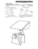
[0018] FIG. 1 shows an exemplary bathing support according to the present invention.
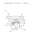
[0019] FIG. 2 depicts projection views of an exemplary support member.
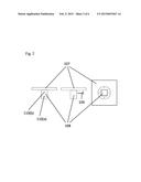
[0020] FIG. 3 shows an alternative view of the exemplary bathing support shown in FIG. 1.
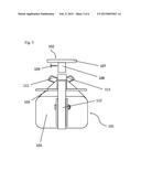
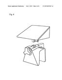
[0021] FIG. 4 shows an exemplary bathing support according to the present invention having an alternative support member design.
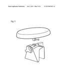
[0022] FIG. 5 shows an exemplary bathing support according to the present invention having an alternative support member design.
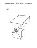
[0023] FIG. 6 shows an exemplary bathing support according to the present invention having an alternative first holding member design.
DETAILED DESCRIPTION OF THE INVENTION
[0024] FIG. 1. depicts a bathing support according to the present invention. Base member 101 and platform member 102 are depicted as being reversibly engaged by insertion of second holding member 108 into first holding member 106. By insertion of pin 109 into hole 110 and alignment of hole 110 with a corresponding hole in first holding member 106, platform member 102 is secured to base member 101.
[0025] The base frame comprises first side member 103, second side member 104, and top member 105. In this case, the second side member 104 and top member 105 are depicted as being formed from one continuous material. First side member is attached to an arm 112 which inserts into channel 113 and is connected to handle 111. This forms the clamping attachment. By rotation of handle 111, a screw mechanism (not shown) moves arm 112 relative to channel 113, and thereby adjusts the spacing between first side member 103 and second side member 104. This movement is used to reversibly secure the bathing support to the tub wall. Platform member 102 provides a support 107 on which the bathing assistant can be supported while leaning into the bath. This support 107 can free both hands if necessary for the bathing task by the bathing assistant sitting or placing his/her torso on platform member 102.
[0026] The various elements of the device are formed of a material or materials having sufficient stiffness to support the weight of the bathing assistant, and may be formed of, for example, a generally water resistant material such as a stiff plastic or metal. When the device is in place, the first holding member 106, which receives the mount point for the platform member 102, is preferably positioned so that it is sitting at the top edge of the tub. In this way, the loading force created by the weight of the bathing assistant can be borne in part by the bathing tub. The distance between the first and second side members 103 and 104 is adjustable via the clamping attachment, so that the frame may be reversibly secured to the bathing tub edge, and so that the device can adapt to different tub wall thicknesses.
[0027] FIG. 2 depicts various projection views of the platform member 102. Second holding member 108 is depicted as a square steel tube attached to a plate which is screwed into the lower surface of support member 107. As depicted, the first holding member 106 reversibly receives and secures the second holding member 107; that is, platform member 102 may be removed from the base member 101.
[0028] First holding member 106 receives and secures second holding member 108 in a sliding fashion, so that the height of the platform member relative to the base member may be adjusted by the user. The second holding member 108 may, for example, comprise a plurality of first pin holes 110(a) and (b) adapted to receive a securing pin 109, and the first holding member 106 comprises at least one corresponding second pin hole, whereby the second holding member 108 is secured to the first holding member 106 by insertion of the securing pin 109 through the first pin hole and the second pin hole. In this embodiment, the first holding member 106 may releasably receive second holding member 108 such that base member 101 and platform member 102 are releasably attached to one another. As used herein, the terms "releasably secure," "releasably attached" and "releasably receive" refers to two elements which may be engaged with, and disengaged from, one another in the course of normal use.
[0029] Other means of permitting the first and second holding members to adjust or be disengaged will be apparent to those of skill in the art. For example, the first holding member may be constructed as a conventional quick-release post comprising a manually operated lever which operates a cam shaft to reversibly secure the second holding member by reducing the inner dimension of the first holding member. Examples of such quick release mechanisms are often used to secure bicycle seat posts within a bicycle frame. Alternatively, the first and second holding members may be fabricated as a single integral unit which joins the base member 101 and platform member 102 in a manner that is not intended to be releasable by the user without dismantling of the device, such as by removal of fastening screws.
[0030] The upper surface of support member 107 is preferably substantially planar. By "substantially planar" is meant that the surface deviates from a flat profile by no more than 10% of its largest planar dimension. For example, such a substantially planar surface may be contoured as a seat, having one or more depressions to fit the anatomical structure of the legs, buttocks, etc. See, e.g., FIG. 5. The upper surface may have a preferably water resistant padding for additional comfort of the user.
[0031] The device may be made such that the upper surface of support member 107 is held at a fixed angle relative to the surface of the water within the tub (this angle being referred to herein as the "angle of incidence"). In certain embodiments, however, the angle of the upper support surface may be adjustable in one or more planes by the user. For example, the lower surface of support member 107 may be mounted to the second holding member 108 using a rotable locking joint such as that used to adjust the saddle angle of a bicycle along a single axis; or a locking universal joint or gimbal may be used to provide adjustment along multiple axes. In certain embodiments, the angle of incidence of the upper support surface is maintained between 0° and 60°. Such rotable couplings may be placed elsewhere on the device to provide this functionality. For example, the first holding member 106 may be mounted to the frame using such a roatble coupling, or such a rotable coupling may join first holding member 106 to second holding member 108. In an alternative, the support member may be shaped to provide an angle of incidence which is not parallel to the surface of the water, as depicted in FIG. 4.
[0032] FIG. 3 depicts a device of the present invention as if viewed from inside the bathing tub. In this embodiment, As discussed above, first side member is attached to an arm 112 which inserts into channel 113 and is connected to handle 111. This forms the clamping attachment. In this embodiment, arm 112 is formed in an inverted "L" shape, in which one arm of the "L" inserts into channel 113, and the other arm of the "L" is attached by bolting to the rear of first side member 103. As depicted in FIGS. 1 and 6, the first holding member may be positioned in a variety of configurations relative to the clamping attachment.
[0033] One skilled in the art readily appreciates that the present invention is well adapted to carry out the objects and obtain the ends and advantages mentioned, as well as those inherent therein. The examples provided herein are representative of preferred embodiments, are exemplary, and are not intended as limitations on the scope of the invention.
[0034] It will be readily apparent to a person skilled in the art that varying substitutions and modifications may be made to the invention disclosed herein without departing from the scope and spirit of the invention.
[0035] All patents and publications mentioned in the specification are indicative of the levels of those of ordinary skill in the art to which the invention pertains. All patents and publications are herein incorporated by reference to the same extent as if each individual publication was specifically and individually indicated to be incorporated by reference.
[0036] The invention illustratively described herein suitably may be practiced in the absence of any element or elements, limitation or limitations which is not specifically disclosed herein. Thus, for example, in each instance herein any of the terms "comprising", "consisting essentially of" and "consisting of" may be replaced with either of the other two terms. The terms and expressions which have been employed are used as terms of description and not of limitation, and there is no intention that in the use of such terms and expressions of excluding any equivalents of the features shown and described or portions thereof, but it is recognized that various modifications are possible within the scope of the invention claimed. Thus, it should be understood that although the present invention has been specifically disclosed by preferred embodiments and optional features, modification and variation of the concepts herein disclosed may be resorted to by those skilled in the art, and that such modifications and variations are considered to be within the scope of this invention as defined by the appended claims.
[0037] Other embodiments are set forth within the following claims.
User Contributions:
Comment about this patent or add new information about this topic:
Images included with this patent application:
 |  |
 |  |
 |  |
 |
| Similar patent applications: | |
| Date | Title |
|---|---|
| 2015-02-12 | Apparatus for generating waves in a swimming pool |
| 2015-02-05 | Electronic tap with operating system at the end of the spout |
| 2014-11-20 | Child bathing activity center |
| 2014-12-04 | Standalone hair washing sink |
| 2014-12-11 | Standalone hair washing sink |
| New patent applications in this class: | |
| Date | Title |
|---|---|
| 2014-11-13 | Bath chair |
| 2014-11-13 | Bath aid structure and bath aid assembly |
| 2014-08-21 | Adjustable bathtub chair |
| 2013-08-15 | Foldable hot tub seat |
| 2012-09-20 | Bath chair |
| Top Inventors for class "Baths, closets, sinks, and spittoons" | |
| Rank | Inventor's name |
|---|---|
| 1 | William T. Ball |
| 2 | Joseph R. Cook |
| 3 | David Grover |
| 4 | Ralph Butter-Jentsch |
| 5 | Kun Yuan Tong |