Patent application title: VEHICLE CONTROL DEVICE AND METHOD
Inventors:
Moon Shik Choi (Anyang-Si, KR)
Assignees:
LSIS CO., LTD.
IPC8 Class: AG07C500FI
USPC Class:
701 291
Class name: Data processing: vehicles, navigation, and relative location vehicle control, guidance, operation, or indication vehicle diagnosis or maintenance determination
Publication date: 2015-01-22
Patent application number: 20150025733
Abstract:
A vehicle control method according to an embodiments includes: collecting
data in a first communication data format from at least one electronic
unit in a vehicle; converting the data collected in the first
communication data format into a second communication data format in
order to be transmitted to a pre-connected destination; transmitting the
converted data to the destination; receiving, from the destination,
control data of the second communication data format corresponding to the
transmitted data; converting the control data of the second communication
data format into the first communication data format; and outputting the
control data of the first communication data format to a corresponding
electronic unit.Claims:
1. A vehicle control method comprising: collecting data in a first
communication data format from at least one electronic unit in a vehicle;
converting the data collected in the first communication data format into
a second communication data format in order to be transmitted to a
pre-connected destination; transmitting the converted data to the
destination; receiving, from the destination, control data of the second
communication data format corresponding to the transmitted data;
converting the control data of the second communication data format into
the first communication data format; and outputting the control data of
the first communication data format to a corresponding electronic unit.
2. The vehicle control method according to claim 1, wherein the first communication data format is a control area network (CAN) communication data format, and the second communication data format is a wireless communication data format.
3. The vehicle control method according to claim 1, wherein the control data converted into the first communication data format is divided into data having a transmission size of the first communication data format, when the control data converted into the first communication data format is output to the corresponding electronic unit.
4. The vehicle control method according to claim 3, wherein a size of the divided data is 8 bytes.
5. The vehicle control method according to claim 1, wherein the collected data is state data of each electronic unit.
6. The vehicle control method according to claim 1, further comprising: temporarily storing the collected data in the first communication data format; and converting the stored data into the second communication data format.
7. The vehicle control method according to claim 1, further comprising: checking information of a monitoring/control device which is the preset destination when a control data reception request is received from the monitoring/control device; and converting control data received from the monitoring/control device into the second communication data format when the information of the monitoring/control device matches preset destination information.
8. The vehicle control method according to claim 7, wherein the control data received from the monitoring/control device is temporarily stored while the information of the monitoring/control device that has transmitted the control data is checked.
9. The vehicle control method according to claim 8, wherein, when the checking the information of the monitoring/control device is completed, the temporarily stored control data is converted into the second communication data format.
10. A vehicle control device comprising: a communication unit configured to collect data from at least one electronic unit in a vehicle, convert the collected data into a data format for transmission to a preset destination, collect control data from the outside, and convert the collected control data into a data format for transmission to the electronic unit; and a control unit configured to control the communication unit so that the data converted by the communication unit is transmitted to the preset destination.
11. The vehicle control device according to claim 10, further comprising a storage unit for storing the collected data.
12. The vehicle control device according to claim 10, further comprising a data conversion unit for converting a data format of the collected data.
13. The vehicle control device according to claim 10, further comprising at least one buffer for temporarily storing the collected data or the converted data.
14. The vehicle control method according to claim 13, wherein the buffer comprises: a first receiving buffer for temporarily storing the data collected from the electronic units of the vehicle; and a second receiving buffer for temporarily storing the control data received from the preset external destination.
15. The vehicle control device according to claim 14, wherein the buffer comprises: a first transmitting buffer for temporarily storing data obtained by converting the data stored in the first receiving buffer; and a second transmitting buffer for temporarily storing data obtained by converting the data stored in the second receiving buffer.
16. The vehicle control device according to claim 10, wherein the converted control data is divided into data having a transmission size of the converted communication data format, when the converted control data is output to the corresponding electronic unit.
Description:
CROSS-REFERENCE TO RELATED APPLICATIONS
[0001] Pursuant to 35 U.S.C. §119(a), this application claims the benefit of earlier filing date and right of priority to Korean Patent Application No. 10-2013-0086238, filed on Jul. 22, 2013, the contents of which are all hereby incorporated by reference herein in its entirety.
BACKGROUND
[0002] The present disclosure relates to a vehicle control device and method, and particularly, to a control device and method using a communication protocol based on a mobile device.
[0003] A plurality of electric control units (ECUs) having microcontrollers are installed in a vehicle. Debugging and calibration of internal system variables are required to develop ECUs.
[0004] In order to calibrate a conventional ECU in a vehicle, a laptop computer is directly connected to a control area network (CAN) communication line of the vehicle through a cable and environment variables are updated.
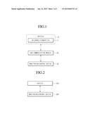
[0005] FIG. 1 is a block diagram illustrating a conventional communication system between a vehicle and an external device.
[0006] Referring to FIG. 1, a CAN communication module 30 is added for communication between a vehicle 10 and a monitoring/control device 20. The vehicle 10 includes an on board diagnostics (OBD) 11 for diagnosing a state of the vehicle, wherein the OBD transmits, to the monitoring/control device, result data obtained through CAN communication with function units in the vehicle. Furthermore, in order to transmit control data for environment variables from the monitoring/control device, the data should be converted into a format compatible with the CAN communication through the CAN communication module.
[0007] In general, the OBD 11 is connected to the monitoring/control device such as a computer or a laptop using the CAN-module-installed interface 30 so as to transfer environment variables for calibrating an ECU. Thereafter, the monitoring/control device updates the environment variables of the ECU using an ECU calibration application program.
[0008] According to the above-mentioned system, the OBD 11 should be connected to the monitoring/control device 30 by wire and an additional data conversion device is required, causing spatial limitation and additional cost.
SUMMARY
[0009] Embodiments provide a system for calibrating an existing electronic unit for a vehicle, and a mobile-device-based vehicle control device and method for overcoming environmental limitations.
[0010] Embodiments provide a mobile-device-based vehicle control device and method for enabling a user to easily perform data transmission and control for calibrating a state of a vehicle.
[0011] Embodiments provide a mobile-device-based vehicle control device and method for enabling a user to control a vehicle state using various devices instead of limited monitoring/control devices.
[0012] In one embodiment, a vehicle control method includes: collecting data in a first communication data format from at least one electronic unit in a vehicle; converting the data collected in the first communication data format into a second communication data format in order to be transmitted to a pre-connected destination; transmitting the converted data to the destination; receiving, from the destination, control data of the second communication data format corresponding to the transmitted data; converting the control data of the second communication data format into the first communication data format; and outputting the control data of the first communication data format to a corresponding electronic unit.
[0013] The details of one or more embodiments are set forth in the accompanying drawings and the description below. Other features will be apparent from the description and drawings, and from the claims.
BRIEF DESCRIPTION OF THE DRAWINGS
[0014] FIG. 1 is a block diagram illustrating a conventional communication system between a vehicle and an external device.
[0015] FIG. 2 is a block diagram illustrating a vehicle control system based on a mobile device according to an embodiment.
[0016] FIG. 3 is a block diagram illustrating a communication unit in the vehicle according to the embodiment.
[0017] FIG. 4 is a flowchart illustrating a method of controlling a vehicle based on a mobile device according to an embodiment.
DETAILED DESCRIPTION OF THE EMBODIMENTS
[0018] It should be understood that the terms used herein should not be construed as being limited to general and dictionary meanings, but should be interpreted based on the meanings and concepts corresponding to technical aspects of embodiments, considering that inventors may define terms appropriately to describe the embodiments.
[0019] Therefore, it should be understood that the embodiments described herein and the configurations illustrated in the drawings are merely preferred examples and do not entirely represent the technical aspects of the embodiments, and thus, various alternative equivalents or modifications could be made at the filing date.
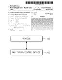
[0020] FIG. 2 is a block diagram illustrating a vehicle control system based on a mobile device according to an embodiment.
[0021] Referring to FIG. 2, the vehicle control system according to the embodiment does not include an additional communication module, but a vehicle 100 may be directly connected to and communicate with a monitoring/control device 200 that acquires data from the vehicle and generates and transmits control data based on the acquired data.
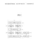
[0022] FIG. 3 is a block diagram illustrating a communication unit in the vehicle according to the embodiment.
[0023] Referring to FIG. 3, the communication unit in the vehicle according to the embodiment includes first and second transmitting buffers 116 and 117, first and second receiving buffers 112 and 114, a data conversion unit 113, and a wireless communication unit 115.
[0024] The in-vehicle communication unit 111, which is a communication unit for communication between electronic units of the vehicle, may include a CAN communication module. Therefore, a format of data obtained from the in-vehicle communication unit 111 may be a CAN communication data format.
[0025] The first receiving buffer 112 may temporarily store the data obtained from the in-vehicle communication unit 111 before the data is output to the data conversion unit 113 so as to be converted into a wireless communication data format.
[0026] The data conversion unit 113 may convert the CAN-communication-format data received from the first receiving buffer 112 or directly received from the in-vehicle communication unit 111 into the wireless communication data format so as to transmit the CAN-communication-format data to an external monitoring/control device. Furthermore, the data conversion unit 113 may convert vehicle control data of the wireless communication data format received from the external monitoring/control device into the CAN communication data format so as to transmit a control signal based on the control data to a corresponding electronic unit.
[0027] The second receiving buffer 114 may temporarily store the data that has been converted from the CAN communication data format into the wireless communication data format in the data conversion unit 113, and may output the stored data to the wireless communication unit 115 after a lapse of a predetermined time or in response to a control signal.
[0028] The wireless communication unit 115 may transmit, to a destination preset by a user, the wireless-communication-format data temporarily stored in the first receiving buffer 114 or obtained in the data conversion unit 113. The destination may be the monitoring/control device 200 that may be a wireless terminal device such as a user mobile terminal. Furthermore, the wireless communication unit 115 may receive control data of the wireless communication data format from the monitoring/control device 200 of the user.
[0029] The first transmitting buffer 116 temporarily stores control data of the wireless communication format received through the wireless communication unit 115. The first transmitting buffer 116 may output the control data to the data conversion unit 113 after a lapse of a predetermined period of time or in response to a control signal.
[0030] The second transmitting buffer 117 may temporarily store the control data converted into the CAN communication data format in the data conversion unit 113, and may output the control data to the in-vehicle communication unit 111 after a lapse of a predetermined period of time or in response to a control signal. Since a maximum size of data for CAN communication is 8 bytes, the length of the wireless communication data is divided by 8 bytes so as to be transmitted. Therefore, the second transmitting buffer 117 divides the control data of the CAN communication data format output through the data conversion unit 113.
[0031] A control unit 120 generates and outputs a control signal for acquiring operation data and state data generated in a plurality of electronic units in the vehicle, at a predetermined time or in real time. Furthermore, the control unit 120 may obtain check and error information about a communication state of a communication unit 110. Furthermore, the control unit 120 may check information on the electronic units in the vehicle and may check monitoring/control devices which are external devices connected through the communication unit 110.
[0032] The storage unit 130 may store data generated by the electronic units in the vehicle and control data received from the external devices. The storage unit 130 may store information on the electronic units in the vehicle and reference data. Furthermore, the storage unit 130 may store information on the monitoring/control devices connected through the communication unit 110.
[0033] The vehicle may further include a user interface for inputting a user control signal and a display unit for displaying state information of the vehicle.
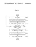
[0034] FIG. 4 is a flowchart illustrating a method of controlling a vehicle based on a mobile device according to an embodiment.
[0035] Referring to FIG. 4, the control unit 120 may collect data including state information of each electronic unit through the in-vehicle communication unit 111 of the communication unit 110 (operation S402).
[0036] The control unit 120 controls the first receiving buffer 112 so that the data collected through the in-vehicle communication unit 111 is temporarily stored in the first receiving buffer 112, and controls the data conversion unit 113 so that the temporarily stored data is converted into a data format so as to be transmitted to an external monitoring/control device.
[0037] The data conversion unit 113 may convert the data of the CAN communication data format collected from the electronic units into the wireless communication data format (operation S404).
[0038] The data of the wireless communication data format obtained through the conversion may be temporarily stored in the second receiving buffer 114 and may be transmitted to a preset monitoring/control device through the wireless communication unit 115 after a lapse of a predetermined time or in response to a control signal of the control unit 120.
[0039] The control unit 120 may continuously monitor whether control data is received from the preset monitoring/control device that has transmitted the data of the electronic units (operation S408).
[0040] When the control unit 120 detects the control data received from a monitoring/control device, the control device 120 may check information of the monitoring/control device stored in the storage unit 130.
[0041] In the case where the monitoring/control device that has transmitted the control data is the preset monitoring/control device as a result of checking the information of the monitoring/control device, the control unit 120 may temporarily store the received data of the wireless communication data format in the second receiving buffer 114. The temporarily stored control data is converted into the CAN communication data format so as to be transmitted to the electronic units in the vehicle (operation S410).
[0042] The control unit 120 may generate a control signal for controlling a corresponding electronic unit on the basis of the data obtained through the conversion (operation S412).
[0043] The control unit 120 may allow the generated control signal to be transmitted to each electronic unit and stored in the storage unit 130. Here, in order to transmit the control signal to each electronic unit, the control unit 120 may divide the control signal by 8 bytes that is a maximum size of the CAN communication data format.
[0044] Although embodiments have been described with reference to a number of illustrative embodiments thereof, it should be understood that numerous other modifications and embodiments can be devised by those skilled in the art that will fall within the spirit and scope of the principles of this disclosure. More particularly, various variations and modifications are possible in the component parts and/or arrangements of the subject combination arrangement within the scope of the disclosure, the drawings and the appended claims. In addition to variations and modifications in the component parts and/or arrangements, alternative uses will also be apparent to those skilled in the art.
User Contributions:
Comment about this patent or add new information about this topic:
Images included with this patent application:
 |  |
 |  |
| Similar patent applications: | |
| Date | Title |
|---|---|
| 2015-02-12 | Vehicle control device, and vehicle control method |
| 2015-02-12 | Vehicle control device and method |
| 2015-02-12 | Vehicle startup control device and startup control method |
| 2015-02-12 | Vehicle height estimation device and vehicle height estimation method |
| 2015-02-12 | Method for operating a brake booster of a vehicle and control device for a brake booster of a vehicle |
| New patent applications in this class: | |
| Date | Title |
|---|---|
| 2019-05-16 | Driverless transportation system |
| 2019-05-16 | Real time streaming analytics for flight data processing |
| 2018-01-25 | Diagnostic testing of rapid heat up of an exhaust sytem during engine decompression |
| 2017-08-17 | System and method for monitoring mining machine efficiency |
| 2017-08-17 | Aircraft weight and balance tool system |
| Top Inventors for class "Data processing: vehicles, navigation, and relative location" | |
| Rank | Inventor's name |
|---|---|
| 1 | Anthony H. Heap |
| 2 | Ajith Kuttannair Kumar |
| 3 | Christopher P. Ricci |
| 4 | Roderick A. Hyde |
| 5 | Lowell L. Wood, Jr. |