Patent application title: FALL PREVENTION AND GUARDRAIL ACCESS POINT DEVICE
Inventors:
Don Mcclendon (Mesa, AZ, US)
IPC8 Class: AE04G514FI
USPC Class:
182113
Class name: Fire escape, ladder, or scaffold safety device, platform associated railing
Publication date: 2014-12-11
Patent application number: 20140360813
Abstract:
A fall protection device can comprise a platform configured to rest on
top of a wall with first and second supports that extend down on opposing
sides of the wall. A rail can be coupled to the platform and comprise
opposing access points and opposing ladder attachment points. A first
movable clamp member can be attached to the first support and configured
to secure the fall protection device to the wall. First and second
ladders can be removably coupled to the opposing ladder attachment
points. The fall protection device can further comprise the first movable
clamp member being attached to the first support adjacent the platform,
and a second movable clamp member being attached adjacent a distal end of
the first support, distal to the platform. The first and second ladders
can be removably coupled to the ladder attachment points on the rail.Claims:
1. A fall protection device, comprising: a platform configured to rest on
a top of a wall with first and second supports that extend down on
opposing sides of the wall; a rail coupled to the platform comprising
opposing access points and opposing ladder attachment points; a first
movable clamp member attached to the first support and configured to
secure the fall protection device to the wall; and first and second
ladders removably coupled to the opposing ladder attachment points.
2. The fall prevention device of claim 1, further comprising: the first movable clamp member attached to the first support adjacent the platform; and a second movable clamp member attached adjacent a distal end of the first support, distal to the platform.
3. The fall prevention device of claim 1, wherein the first and second supports are separated by a distance of at least 15 centimeters to provide a space for the wall.
4. The fall prevention device of claim 1, wherein a line perpendicular to a first access point aligns with a first segment of rail and a line perpendicular to a second access point aligns with a second segment of rail opposite the first segment of rail.
5. The fall prevention device of claim 1, wherein the first and second ladders are removably coupled to the ladder attachment points on the rail such that rungs of the ladders extend above and below the platform when coupled to the rail.
6. The fall prevention device of claim 1, wherein the opposing access points include a width less than or equal to about 48 centimeters.
7. A fall prevention device, comprising: a platform; first and second supports coupled to the platform that extend from the platform in a first direction; a rail coupled to the platform that extends in a second direction opposite the first direction and further comprises opposing access points; and a first movable clamp member attached to the first support that is configured to adjustably extend toward the second support.
8. The fall prevention device of claim 7, further comprising first and second ladders removably coupled to the rail adjacent to the opposing access points.
9. The fall prevention device of claim 7, further comprising: the first movable clamp member coupled to the first support adjacent the platform; and a second movable clamp member coupled adjacent a distal end of the first support opposite the platform.
10. The fall prevention device of claim 7, wherein the first support and the second support are separated by a distance of at least 15 centimeters to provide a space for a wall.
11. The fall prevention device of claim 7, wherein the rail and supports are integrally formed of continuous members that extend across the platform to the first and second opposing sides.
12. The fall prevention device of claim 7, wherein the opposing access points in the rail are offset with respect to each other.
13. The fall prevention device of claim 7, wherein the first and second ladders are removably coupled to the ladder attachment points on the rail such that rungs of the ladders extend in both the first and second directions from the platform when coupled to the rail.
14. A method of providing fall protection, comprising: disposing a platform over a wall with first and second supports that extend down opposing sides of the wall and further comprises a rail that extends opposite the supports and further comprises opposing first and second access points; and securing the first support, second support, and platform to the wall.
15. The method of claim 14, further comprising rigidly securing the first support and the second support to the wall by adjustably extending a portion of a movable clamp member to contact the wall and apply a force between the first support and the wall.
16. The method of claim 15, further comprising: coupling a first ladder adjacent to the first access point; and coupling a second ladder adjacent to the second access point.
17. The method of claim 16, further including coupling the first and second ladders such that rungs of the first and second ladders extend above and below the platform.
18. The method of claim 14, further including providing the opposing first and second access points with a width less than or equal to about 48 centimeters.
19. The method of claim 14, further comprising separating the first and second supports by a distance of at least 15 centimeters to provide a space for the wall.
20. The method of claim 14, further comprising providing the opposing first and second access points with an offset such that a user passing from the first access point across the platform to the second access point passes between first and second portions of the rail.
Description:
TECHNICAL FIELD
[0001] Embodiments of the present disclosure relate to the field of fall prevention and fall protection devices that include applications for safety systems and apparatus, such as guardrail access devices, for increasing safety at an edge of an elevated surface such as at a roof edge or at a firewall.
BACKGROUND
[0002] A person needing access to a rooftop oftentimes needs to climb a ladder from a first level (such as ground level) to a height of the rooftop. The rooftop, especially of a building with a flat roof, can be at least partially encircled by a wall. The wall can be an exterior wall of the building or a firewall separating two or more portions of the building. When a height between the top of the building wall and the rooftop is sufficiently high, a person might have difficulty descending from the top of the wall to the rooftop. Even if the height between the top of the building wall and the rooftop is not problematic in itself, some agencies and regulatory bodies, such as the Occupational Safety and Health Administration (OSHA) in the United States, might require a guardrail or guardrail system be installed along the top of a wall to help prevent persons from falling when near an edge of the rooftop. Accordingly, a height between the rooftop and the top of the guardrail might be problematic for a person accessing the rooftop.
[0003] In some instances, a second ladder might be used for a person to descend from the top of the wall to the rooftop. Safely making a transition between first and second ladders resting on opposing first and second sides of the wall can be problematic because a person can, in transitioning between the first and second ladders, loose his balance and fall. Falls are undesirable because they can be dangerous, resulting in a person's injury or death. A need exists for providing a way in which a person can safely, easily, and reliably access a rooftop with a wall, including a wall with a guardrail system, to reduce a risk of falling.
SUMMARY
[0004] A need exists to provide a simple, efficient, and cost effective fall prevention device. Accordingly, in one aspect, a fall protection device can comprise a platform configured to rest on top of a wall with first and second supports that extend down on opposing sides of the wall. A rail can be coupled to the platform and comprise opposing access points and opposing ladder attachment points. A first movable clamp member is attached to the first support and configured to secure the fall protection device to the wall. First and second ladders are removably coupled to the opposing ladder attachment points.
[0005] The fall protection device can further comprise the first movable clamp member being attached to the first support adjacent the platform, and a second movable clamp member being attached adjacent a distal end of the first support, distal to the platform. The first and second supports can be separated by a distance of at least 15 centimeters (cm) (or 6 inches (in.)) to provide a space for the wall. A line perpendicular to a first access point or rail opening can align with a first segment of rail and a line perpendicular to a second access point or rail opening can align with a second segment of rail opposite the first segment of rail. The first and second ladders can be removably coupled to the ladder attachment points on the rail such that rungs of the ladders extend above and below the platform when coupled to the rail. The opposing access points can include a width less than or equal to about 48 cm (or 19 in.).
[0006] In another aspect, a fall protection device can comprise a platform. First and second supports can be coupled to the platform that extend from the platform in a first direction. A rail coupled to the platform can extend in a second direction opposite the first direction and further comprise opposing access points. A first movable clamp member can be attached to the first support and be configured to adjustably extend toward the second support.
[0007] The fall protection device can further comprise first and second ladders removably coupled to the rail adjacent to the opposing access points. The first movable clamp member can be coupled to the first support adjacent the platform, and a second movable clamp member can be coupled adjacent a distal end of the first support opposite the platform. The first support and the second support can be separated by a distance of at least 15 cm (or 6 in.) to provide a space for a wall. The rail and supports can be integrally formed of continuous members that extend across the platform to the first and second opposing sides. The opposing access points in the rail can be offset with respect to each other. The first and second ladders can be removably coupled to the ladder attachment points on the rail such that rungs of the ladders extend in both the first and second directions from the platform when coupled to the rail.
[0008] In yet another aspect, a method of providing fall protection can comprise disposing a platform over a wall with first and second supports that extend down opposing sides of the wall and further comprises a rail that extends opposite the supports and further comprises opposing first and second access points, and securing the first support, second support, and platform to the wall.
[0009] The method of providing fall protection can further comprise rigidly securing the first support and the second support to the wall by adjustably extending a portion of a movable clamp member to contact the wall and apply a force between the first support and the wall. The method can further comprise coupling a first ladder adjacent to the first access point, and coupling a second ladder adjacent to the second access point. The method can further comprise coupling the first and second ladders such that rungs of the first and second ladders extend above and below the platform. The method can further comprise providing the opposing first and second access points with a width less than or equal to about 48 cm (or 19 in.). The method can further comprise separating the first and second supports by a distance of at least 15 cm (or 6 in.) to provide a space for the wall. The method can further comprise providing the opposing first and second access points with an offset such that a user passing from the first access point across the platform to the second access point passes between first and second portions of the rail.
BRIEF DESCRIPTION OF THE DRAWINGS
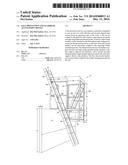
[0010] FIG. 1 illustrates a perspective view of an embodiment of a fall prevention device coupled to a wall.
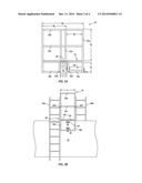
[0011] FIGS. 2A-2C illustrate side and top views of an embodiment of a fall prevention device coupled to a wall.
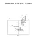
[0012] FIG. 3 illustrates detail of movable clamp members coupled to a fall prevention device.
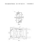
[0013] FIG. 4 illustrates a plan view of a building with various fall protection devices providing access to portions of the building roof
DETAILED DESCRIPTION
[0014] Embodiments in the disclosure present devices, methods, and systems to improve fall protection and fall prevention for use with guardrails, including situations in which a user transitions between first and second ladders.
[0015] In the following description, numerous specific details are set forth, such as specific configurations, sizes, compositions, and processes, in order to provide a thorough understanding of the disclosure. In other instances, well-known aspects have not been described in particular detail in order to not unnecessarily obscure the disclosure. Furthermore, it is to be understood that the various embodiments shown in the FIGs. are illustrative representations and are not necessarily drawn to scale.
[0016] The terms "over," "under," and "between," as used herein, refer to relative positions of one feature with respect to other features. One feature deposited or disposed above, below, over, or under another feature may be directly in contact with the other feature or may have one or more intervening features. One feature deposited or disposed between features may be directly in contact with the features or may have one or more intervening features. A first feature "on" a second feature may be directly in contact with the second feature or may have one or more intervening features.
[0017] FIG. 1 shows a perspective view of fall prevention device or guardrail access device 10 mounted on, and coupled to, wall 12. Fall prevention device 10 includes platform 14 that is configured to rest on or over wall 12. Wall 12 includes a vertical structure or barrier that a user, such as a workman, may desire to cross. Wall 12 can be made of block, brick, stone, concrete, or other suitable material. In an embodiment, wall 12 is an exterior wall of a building or a firewall separating portions of a building as shown, for example, in FIG. 4 and described in greater detail below.
[0018] Platform 14 includes a length L1 that is less than a length of L2 of wall 12. In an exemplary embodiment, platform 14 includes a length L1 in a range of about 45-75 cm (or 18-30 in.), and in another embodiment, a length L1 of about 61 cm (or 24 in.). Platform 14 also includes a width W1 that is greater than a width W2 of wall 12. In an exemplary embodiment, platform 14 includes a width W1 in a range of about 90-150 cm (or 36-60 in.), and in another embodiment, a length L1 of about 120 cm (or 48 in.). Accordingly, a portion of platform 14 can rest on, and be supported by, wall 12. In an embodiment, a center portion of platform 14 rests on wall 12 such that opposing first and second distal ends of the platform are cantilevered from the wall and extend outside a footprint of the wall. Typical non-limiting examples of widths of wall 12 include a width W2 in a range of about 10-25 cm (or 4-10 in.), or alternatively in a range of about 15-20 cm (or 6-8 in.).
[0019] Fall prevention device 10 further comprises first and second supports 18a and 18b, respectively, that are made of metal, wood, plastic, composite material, or any other suitable material including segments of angle iron, or tubing with angled, circular, square, or other suitable cross-sectional shape. Supports 18 are coupled to platform 14 and extend downward, or in a first direction, from platform 14 and are disposed along opposing sides of wall 12 when fall prevention device 10 is mounted to the wall. Additionally, supports 18 can further include a horizontal connecting member that is connected to the downward extending portions, wherein the horizontal connecting member spans between opposing sides of wall 12 such that supports 18 comprise a "C" shaped portion offset from three sides of wall 12. In an embodiment, supports 18 are made of two-inch angle iron that is welded to platform 14. Supports 18 include a height H1 that is less than or equal to a height H2 of wall 12. In an exemplary embodiment, height H1 is in a range of about 30-60 cm (or 12-24 in.), and alternatively, height H1 can have a height of about 45 cm (or 18 in.).
[0020] A rail 22 comprises one or more rails, slats, strips, sheets, panels, webs, other suitable forms, or combination of suitable forms that can be made of one or more various materials such as metal, wood, plastic, cord, cable, chain, composite material, or any other suitable material. In an embodiment, rail 22 can include segments of angle iron, or tubing with an angled, circular, square, or other suitable cross-sectional shape. Rail 22 is coupled to platform 14 or supports 18 and extends upward, or in a second direction, from platform 14 opposite the first direction of supports 18. Rail 22 can comprise a number of vertical rail members 22a, and a number of horizontal members 22b and 22c. Alternatively, as mentioned above, rail 22 can also includes panels, sheets, webs, and other suitable structures or forms that are planar or can extend in both vertical and horizontal directions such that a single panel can be used in place of, or in combination with, any number of vertical and horizontal rail members 22a, 22b, and 22c. In an embodiment, rail 22 comprises four vertical members 22a that are positioned at four corners of platform 14 and can be made of two-inch square angle iron that is welded to the platform, although members of any size can also be used. The four corner vertical rail members 22a can be discrete members that begin at platform 14 and extend away from the platform, or alternatively, can be single or unitary pieces that integrally form both a portion of supports 18a and 18b as well as the vertical rail members 22a and encompass a height that includes the sum of H1, H3, and a height of platform 14. In an embodiment, the overall height of fall prevention device 10 (that is the sum of H1, H3, and a height of platform 14) is about 152.4 cm (or 5 feet). Vertical rail members 22a can also include one or more exist posts that define a portion or edge of access points 26, which are discussed in greater detail below. Rail 22 includes a height H3 above platform 14 that prevents the user from falling off the platform and helps maintain the user on the platform, thereby preventing injury and accidental falls. Height H3 can be adjusted, for example, for a height of a user or according to safety regulations, guidelines, codes, or requirements imposed by local, regional, national, or other authority. In an exemplary embodiment, rail 22 includes a height H3 in a range of about 90-120 cm (or 36-48 in.), and in another embodiment, H3 that can be about 107 cm (or 42 in.) or any other suitable height. Height H3 can also be fixed or adjustable.
[0021] In an exemplary embodiment, rail 22 can further include upper or top horizontal member 22b disposed at about 107 cm (or 42 in.) above platform 14, which can also serve as a handrail. Rail 22 can further include an intermediate horizontal member 22c that can be disposed at about a middle of rail 22, for example at about 53 cm (or 21 in.) above platform 14. In an exemplary embodiment, upper horizontal member 22b and intermediate horizontal member 22c can be formed of one inch square metal tubing. Vertical members 22a of rail 22 can be connected or coupled to upper and intermediate horizontal members 22b and 22c, respectively, by welding or other suitable process or device. Members 22a-22c are also shown in elevational view in FIGS. 2A and 2B. While non-limiting exemplary heights have been provided for members 22a-22c, any desired height(s) can be used for any number or configuration of rails, including angled, slanted, or crisscross orientations for preventing falls and containing a user on platform 14. In some embodiments, openings in rail 22 are less than about 48.3 cm (or 19 in.) to comply with OSHA regulations; however, any maximum opening size can be used to comply with any relevant regulation. In an exemplary embodiment, members 22b and 22c can serve as end rails comprising a length L1, which can be about 61 cm (or 24 in.).
[0022] Rail 22 further comprises opposing access points 26 that are formed as openings or gaps in rail 22 that are large enough for a person, such as a workman, to pass through for ingress and egress with respect to platform 14. Access points 26 are configured to allow passage of a user onto platform 14. In an embodiment, access points 26 include a height H3, equal to a height of rail 22, and further include a width in a range of about 45-110 cm (or 18-42 in.), although larger and smaller widths of any size can also be used. In a particular embodiment, openings 26 include a width less than or equal to 50.8 cm (or 20 in.) so that under current OSHA laws and regulations a chain is not required to extend across the opening. Alternatively, a chain, bar, belt, rail, web, door, or other suitable device can be removably extended across and attached to opposing sides of opening 37 to help prevent a user from falling through the opening.
[0023] The width of access points 26 is less than a width W3 of rail 22 in a direction taken transverse to length L1 of fall prevention device 10 and L2 of wall 12. In an embodiment, the width W3 of rail 22 is in a range of about 15-105 cm (or 6-41 in.), and can be a length of 71 cm (or 28 in.).
[0024] A number of movable clamp members or jacks 30 are coupled to one or more of platform 14, supports 18, and rail 22. Taken together, movable clamp members 30 and one or more portions of platform 14, supports 18, and rail 22 form a clamp, by which fall prevention device 10 is removably coupled to wall 12. Accordingly, fall prevention device 10, can itself, be considered a large clamp configured to facilitate passage of a person across a wall using first and second ladders, as is described in greater detail below. Furthermore, fall prevention device 10 can be considered a device comprising a platform that rests on a top of a wall, wherein movable clamp members 30 temporarily and removably couple fall prevention device 10 to wall 12. Movable clamp members 30 can include any number of mechanical, electrical, electromechanical, chemical, or material features for removably coupling fall prevention device 10 to wall 12, such as clamps, clamp rails, brackets, catches, clasps, presses, vices, jacks, screw jacks, scissor jacks, hydraulic jacks, suction devices, or other suitable devices including, without limitation, springs, pistons, hydraulics, threaded shafts, clamps, rods, pins, suction devices, or other suitable features. In an embodiment, first and second movable clamp members 30 are vertically aligned along top and bottom portions of first support 18 and/or on platform 14 and can be centered along length L1 of fall prevention device 10. As such, a centerline of movable clamp members 30 taken along a length of the movable clamp members can be disposed a distance of about 30 cm (or 12 in.) from the outer edges of fall prevention device 10. The centerline of movable clamp members 30 can further be disposed approximately 9 cm (or 3.5 in.) from top and bottom portions of supports 18 or platform 14. Additionally, any number of movable clamp members 30 can be used on any number of supports. For example, two movable clamp members 30 can be coupled to a single support, such as support 18a and 18b that can extend down on opposing sides of wall 12. Alternatively, two movable clamp members 30 can be coupled to opposing supports, such as supports 18a and 18b, so that the clamp members are disposed on opposing sides of wall 12. Movable clamp members 30 can be user-adjustable, and can be configured to be engaged by a user to fixedly and rigidly couple fall prevention device 10 to wall 12 by extending a portion of the movable clamp members toward the wall. In an embodiment, movable clamp members 30 are screw jacks that include a body 32, a handle 34 attached to a first end of the body, and a foot 36 attached to a second end of the body opposite the first end. Handle 34 can be rotatably coupled to body 32 such that when handle 34 is rotated, foot 36 extends from body 32. When screw movable clamp member 30 is mounted to first support 18a, movably engaging handle 34 extends foot 36 from body 32 toward second support 18b, such that a portion of movable clamp member 30 is configured to move toward wall 12 when platform 14 is disposed over the wall. Advantageously, a gap 40 can be formed by a space between supports 18a and 18b such that the gap includes a space that extends between opposing edges 42a and 42b of supports 18a and 18b, respectively. Accordingly, when fall prevention device 10 is positioned with gap 40 disposed over wall 12, movably engaging handle 34 extends foot 36 from body 32 of screw movable clamp member 30 toward second support 18b. Foot 36 is then brought in contact with wall 12 and applies a compressive force between fall prevention device 10 and wall 12 that is directed between the wall and opposing supports 18a and 18b through one or more movable clamp members 30. In an embodiment, movable clamp members 30 can be screw jacks that include a weight rating, or be designed to apply a force of, approximately 680 kilograms (kg.) or 1,500 pounds (lbs.). Additional detail of movable clamp members 30 is shown in FIG. 3.
[0025] Fall prevention device 10 further comprises a number of ladder attachment points 44. Ladder attachment points 44 are disposed on opposing sides of fall prevention device 10 near openings 26. Ladder attachment points 44 can include a number of attachment points disposed along height H1 of supports 18, along height H3 of rail 22, and at any other point on fall prevention device 10. In an embodiment, ladder attachment points 44 can include a first ladder attachment point 44a on the upper horizontal member 22b of rail 22, a second ladder attachment point 44b on intermediate horizontal member 22c of rail 22, and a third ladder attachment point 44c on support 18. Ladder attachment points 44 are configured to receive removably attachable ladders 46. Ladders 46 are removably attachable with flexible or rigid straps, cords, belts, ties, zip ties, hooks, clips, pins, latches, clamps, clamp rails, brackets, catches, clasps, presses, vices, suction devices, or other suitable attachment devices made of metal, plastic, wood, resin, composite, or other suitable material that can be fixedly or removably coupled to fall prevention device 10 as part of ladder attachment points 44. FIG. 1 shows a first ladder 46a attached to fall prevention device 10 such that a center area or midpoint 48 of ladder 46a is positioned adjacent to, and substantially in-line with, platform 14, such that a number of rungs 47 of ladders 46 extend above the platform opposite supports 18. Second ladder 46b is similarly attached to fall prevention device 10 opposite first ladder 46a. Alternatively, a top portion or top rung of ladders 46 can align with platform 14. FIG. 2B shows ladders 46a and 46b attached to fall prevention device 10 at ladder attachment points 44b, respectively, with ties or zip ties.
[0026] Fall prevention device 10 can be placed on wall 12 by a user without assistance from tools or machines. Alternatively, users can be assisted by lifts, cranes, levers, ropes, block and tackle, or other tools or machines in placing fall prevention device 10 on wall 12. In an embodiment, fall prevention device 10 includes a weight in a range of about 35-55 kg (or 80-120 lbs.). Similarly, fall prevention device can include a weight of about 45 kg (or 100 lbs.) and be light enough to be readily moved and lifted into position by one or more users.
[0027] FIGS. 2A-2C show various views of fall prevention device 10 that was shown in FIG. 1. Specifically, FIG. 2A shows an elevation or side-view of fall prevention device 10. The elevational view of FIG. 2A is taken in a direction parallel to length L1 of fall prevention device 10 and parallel to length L2 of wall 12. FIG. 2A shows a cross-sectional portion of wall 12 disposed within gap 40. In an embodiment, gap 40 can include a height of approximately 30-60 cm (or 12-24 in.) and a width in a range of approximately 15-30 cm (or 6-12 in.). A length of gap 40 (shown into the page in FIG. 2A) can be equal to L1, the length of fall prevention device 10, which as described above can be equal to a distance of about 61 cm (or 24 in.). A portion of gap 40 can be occupied by a portion of wall 12 such that a first face of wall 12 is in contact with edge 42b of support 18b and a second face of wall 12 opposite the first face is in contact with feet 36 of movable clamp members 30.
[0028] FIG. 2B shows an elevation or side-view of fall prevention device 10. The elevational view of FIG. 2A is taken in a direction transverse to length L1 of fall prevention device 10 and transverse to length L2 of wall 12. Accordingly, the view of FIG. 2B is taken 90 degrees from the view of FIG. 2A and is parallel to the width W1 of fall prevention device 10.
[0029] FIG. 2B shows ladder 46a attached to fall prevention device 10 at ladder attachment points 44b and 44c with ties or zip ties, while ladder 46b is attached to fall prevention device 10 at ladder attachment point 44d. Ladders 46a and 46b are separated by a length L1 of fall prevention device 10, which, in an embodiment, can be equal to a distance of about 61 cm (or 24 in.).
[0030] FIG. 2B also shows platform 14 can comprise a support portion 14a and a deck portion 14b. Support portion 14a, like supports 18 and rail 22, can be made of metal, wood, plastic, composite material, or any other suitable material including segments of angle iron, or tubing with an angled, circular, square, or other suitable cross-sectional shape. Support portion 14a of platform 14 can be made of material that is the same or different from the material of supports 18 and rail 22. In an embodiment, support portion 14a can include a perimeter portion that is formed at a periphery or outer edge of fall prevention device 10, and can include a footprint that at least partially overlaps with a footprint of rail 22 and supports 18. Support portion 14a can also include additional reinforcing members that are coupled to, and extend between, adjacent and opposing segments of the perimeter portion. Deck portion 14b of platform 14 can be made of metal, wood, plastic, composite material, or any other suitable material formed as slats, strips, sheets, panels, other suitable forms, or combinations of suitable forms. In some embodiments, platform 14 consists of only deck portion 14b that is directly attached to one or more of supports 18, rail 22, and movable clamp members 30. In a particular embodiment, deck portion 14b is expanded metal that is spot welded to support portion 14a or supports 18, which are formed of 2-inch angle iron.
[0031] FIG. 2C shows a plan or top-view of fall prevention device 10. More specifically, FIG. 2C shows a cut-away view of deck portion 14b that reveals portions of support portion 14a or support 18 and movable clamp member 30. As shown in FIG. 2C, an additional support or strut can be added as part of support portion 14a opposite, and aligned with, one or more movable clamp members 30 to provide additional strength and support to platform 14 and fall prevention device 10 as a whole. By forming the support or strut opposite and aligned with the one or more movable clamp members 30, the support or strut provides structural support and reinforcement in response to the force applied by movable clamp members 30 when feet 36 are pressed against wall 12. In an exemplary embodiment, a footprint of platform 14 is equal to a footprint of fall prevention device 10 and can include a length, L1, of approximately 60 cm (or 2 feet) and a width, W1, of approximately 120 cm (or 4 feet).
[0032] While FIG. 2C shows a center of fall prevention device 10 disposed over and aligned with a center of a straight or non-angled segment of wall 12, fall prevention device can also be configured to be disposed over a corner of a building or an angled portion of a wall such that first and second angled portions of the wall could extend away from adjacent sides of the fall prevention device. When fall prevention device 10 is disposed over an angled segment of a wall, a number of movable clamp members 30 might be aligned at various angles with respect to each other, such as 90 degrees, and might not be parallel with respect to each other. Additionally, when configuring fall prevention device 10 to fit over wall segments of different sizes and shapes, a position or location of openings 26 can be positioned such that one or more openings 26 are disposed in-line with one another rather than being staggered or offset with respect to each other and rail 22.
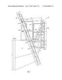
[0033] FIG. 3 shows an enlarged perspective view of a portion of fall prevention device 10, similar to the view shown in FIG. 1. FIG. 3 provides additional detail of a particular embodiment in which movable clamp members 30 are coupled to support 18a and/or platform 14 by intermediate support or strut 49. Support 49, like support portion 14a, support 18a, or rail 22, can be made of metal, wood, plastic, composite material, or any other suitable material including segments of angle iron, or tubing with an angled, circular, square, or other suitable cross-sectional shape. Support 49 can be made of material that is the same or different from the material of support portion 14a, support 18a, and rail 22. Support 49 is both an intermediary for attaching movable clamp members 30 to support 18 or platform 14 as well as a structural member that provides reinforcement to fall prevention device 10, including when feet 36 of movable clamp members 30 contact and apply a force to wall 12. In a particular embodiment, support 49 is made of 2-inch angle iron that is welded to both support 18a or platform 14 and body 32 of movable clamp members 30.
[0034] FIG. 4 is a plan or top-view that shows an implementation of multiple fall prevention devices 10 on a building 50 to provide access to the roof of the building. A first fall prevention device 10 is disposed over an exterior wall 12a of building 50 such that ladders 46 provide access between ground level 52 and first portion of roof 54. First portion of roof 54 is separated from second portion of roof 56 by firewall 12b, which provides vertical separation between first portion of roof 54 and second portion of roof 56. Additionally, first portion of roof 54 and second portion of roof 56 can have different elevations or heights with respect to each other. FIG. 4 also shows a second fall prevention device 10 is disposed over and attached to firewall 12b such that ladders 46 provide access between first portion of roof 54 and second portions of roof 56.
[0035] If a difference in height or elevation between first portion of roof 54 and second portion of roof 56 is greater than a certain height, the installation of guardrails might be required for worker safety. Similarly, if a height or elevation between a top portion of wall 12 is less than a specific minimum standard with respect to first portion of roof 54 and second portion of roof 56, then guardrails might be required along wall 12 to increase worker safety. For example, at the present time OSHA requires that guardrails be put in place for work environments in which less than 32 inches of height separate a roof and a surrounding firewall or exterior wall. U.S. Pat. No. 6,038,829 discloses an exemplary guardrail system known in the art, that could be used to provide a guardrail on walls 12a and 12b around first and second roof portions 54 and 56. When a guardrail system is used along walls 12a or 12b, one or more fall prevention devices 10 can operate as guardrail access points. By terminating the guardrail at a location in which the fall prevention devices and ladders 46 are positioned, a user or worker can pass between opposing sides of the guardrail while being protected by rail 22 of fall prevention device 10. A height of rail 22 can be made, or adjusted, to be in conformance with relevant jurisdictional requirements. While first and second roof portions 54 and 56 are shown in FIG. 4, any number of additional roof portions and a corresponding number of additional fall prevention devices 10 could also be used as part of a system for providing guardrail access or fall protection.
[0036] FIG. 4 further shows a path 58 that a user would travel when using fall prevention device 10. In an embodiment, the user would proceed as indicated by arrow 58a up ladder 46 to opening 26 in rail 22 and pass through the opening onto platform 14. The user would then proceed along width W1 of fall prevention device 10 to a second opening 26 in rail 22. Next, the user would pass through second opening 26 and climb down second ladder 46 as indicated by arrow 58c. The above process could be used to travel between ground level 52 and first portion of roof 54, between first portion of roof 54 and second portion of roof 56, or between any levels connected by fall prevention device 10.
[0037] By following path 58, a user can traverse fall prevention device 10 in a zigzag or stair-step pattern, rather than traveling straight across platform 14, because of the offset of openings 26 in rail 22. As shown in FIG. 4, path 58b includes a first portion that extends in a direction perpendicular to a first opening 26 that aligns with a first segment of rail 22. Similarly, path 58b includes a second portion parallel to the first portion that extends in a direction perpendicular to a second opening 26 that aligns with a second segment of rail 22 opposite the first segment of the rail. The first and second rail segments can be parallel with respect to each other and perpendicular with respect to the first and second portions of path 58b. The first and second portions of path 58b can be parallel and connected by a third portion of the path that, optionally, is perpendicular or angled with respect to the first and second portions of path 58b.
[0038] In the foregoing specification, various embodiments have been described. It will, however, be evident that various modifications and changes may be made thereto without departing from the broader spirit and scope set forth in the appended claims. The specification and drawings are, accordingly, to be regarded in an illustrative sense rather than a restrictive sense.
User Contributions:
Comment about this patent or add new information about this topic:
| People who visited this patent also read: | |
| Patent application number | Title |
|---|---|
| 20190314805 | A PROCESS FOR PRODUCING A CATALYST COMPRISING AN INTERMETALLIC COMPOUND AND A CATALYST PRODUCED BY THE PROCESS |
| 20190314804 | SOLUTION-BASED APPROACH TO MAKE POROUS COATINGS FOR SINTER-RESISTANT CATALYSTS |
| 20190314803 | SUPERLUBRICIOUS CARBON FILMS DERIVED FROM NATURAL GAS |
| 20190314802 | HONEYCOMB STRUCTURE |
| 20190314801 | SCR CATALYST DEVICE CONTAINING VANADIUM OXIDE AND MOLECULAR SIEVE CONTAINING IRON |
Images included with this patent application:
 |  |
 |  |
 |
| Similar patent applications: | |
| Date | Title |
|---|---|
| 2014-11-06 | Mobile access unit and cage |
| 2013-05-23 | Advanced guard rail |
| 2014-09-11 | Elevator and escalator tool |
| 2013-01-10 | Access device |
| 2013-05-16 | Access device |
| New patent applications in this class: | |
| Date | Title |
|---|---|
| 2019-05-16 | Personnel lift vehicle |
| 2019-05-16 | Split deck rail |
| 2016-06-16 | Apparatus for trestle ladder |
| 2016-06-09 | Adjustable scaffold assembly |
| 2016-05-26 | Foldable walkway |
| Top Inventors for class "Fire escape, ladder, or scaffold" | |
| Rank | Inventor's name |
|---|---|
| 1 | N. Ryan Moss |
| 2 | Thomas W. Parker |
| 3 | Sean R. Peterson |
| 4 | Scott C. Casebolt |
| 5 | Gary M. Jonas |