Patent application title: Concrete Flooring
Inventors:
Fergus Ronald Miller (Wilmslow, GB)
Stephen Gerard Peter Blundell (Bramhall, GB)
IPC8 Class: AE04B523FI
USPC Class:
52292
Class name: Static structures (e.g., buildings) footing or foundation type
Publication date: 2014-12-11
Patent application number: 20140360116
Abstract:
An improved concrete floor arrangement is formed from a single cast piece
or alternatively a plurality smaller cast pieces linked together to form
a floor surface. The floor is arranged in the form of a grid.Claims:
1. A concrete floor structure which comprises a framework enclosing a
series of expandable tubular members, said expandable tubular members
being expandable to an extent limited by the framework and wherein, said
expandable members are restricted in their movement by the rigidity of
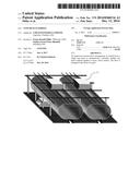
the framework such that said members adopt a position of having a
flattened top and/or bottom thereto.
2. An improved concrete floor structure according to claim 1, wherein said floor structure is formed as a plurality of pre-cast floor pieces which when placed together form a floor structure.
3. An improved concrete floor structure according to claim 1 wherein said floor can be formed by a single cast piece or a number of smaller cast pieces joined together in any suitable manner to form a single floor structure.
4. (canceled)
5. An improved concrete floor structure according to claim 1 wherein a void is provided within the floor structure which is accessible through an aperture.
6. A concrete floor structure comprising a void provided with an aperture as claimed in claim 5 wherein the aperture may be closed off with a closure in the form of a plug.
Description:
[0001] This invention relates to improvements in or relating to concrete
floors and in particular to the creation of accessible void spaces within
said floor structure which consequently produce a structurally efficient
floor containing significantly less material
[0002] The formation of void spaces in current concrete floor structures is thought to produce a benefit since such voids can be arranged to have functionality in a number of different advantageous ways. In order to resolve the issues which arise in relation to prior art of the kind being considered, the limitations of the system need to be overcome or at least minimised.
[0003] Limitations previously used have not had any significant effect in resolving any remaining issues which still remain unaddressed.
[0004] It is accordingly an object of the present invention to provide a concrete floor structure which overcomes or at least minimises the problems associated with the use of existing concrete floor solutions.
[0005] Thus and in accordance with the present invention, there is provided a concrete floor structure which comprises a framework enclosing side-by-side expandable tubular members, said expandable tubular members being expandable to an extent limited by the framework and wherein, said floor structure is restricted in its movement by the rigidity of the framework and forces said members to adopts a position in which they have a flattened top and/or bottom thereto.
[0006] With this arrangement it is possible to provide a concrete floor structure which causes a void to be created within the flooring which is accessible through an aperture, the aperture being capable of being easily closed off when required by insertion of a closure in the form of a plug.
[0007] Preferably, said floor structure is formed into a plurality of pre-assembled pieces which when placed adjacent to each other can be used to form a floor structure.
[0008] The floor structure may be formed as a single cast piece or can be formed as a number of smaller cast pieces which can be joined together in any suitable manner to form a single floor structure.
[0009] The invention will now be described further by way of example only and with reference to the accompanying drawings in which:
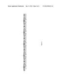
[0010] FIG. 1 shows one embodiment of flooring of the type of the present invention;
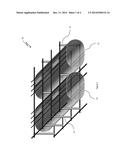
[0011] FIG. 2 shows the floor of FIG. 1 in which a plug and top hat device as described herein after;
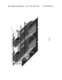
[0012] FIG. 3 shows a diagrammatic representation of a side view in accordance with the present invention.
[0013] It is instructive to consider the state of the art at the time that the present invention was devised and which, even at that time, it was possible to create a concrete floor used by casting.
[0014] Referring now to the figures, FIG. 1 shows a first example of a method of construction of a suitable floor by way of a single casting of concrete in a single piece and with the single opening providing access to the interior of the voids. This type of concrete floor is referred to as "flat slab".
[0015] A second prior art form of a flooring of the type of the present invention has concrete cast for the purpose of use in this "hybrid concrete floor" in which the component parts are cast firstly and are then installed into the frame to form concrete walls and floor of a building.
[0016] Both of these types of concrete can accommodate and/or include a system in which the formation of voids is possible.
[0017] However, the concrete frames formed using the prior art systems described above cannot be installed so as to provide a desired shape of flooring which can then be accessed from externally of the floor. This is achieved by having an external plug that provides access to voids created in the flooring and this can be achieved by removing the plug. Once completed, the plug can be reinserted to close off the voids from the outside world.
[0018] Referring now to the drawings, there is shown in FIG. 1 a perspective view of one embodiment of concrete floor structure formed in accordance with the present invention.
[0019] The concrete floor structure 10 shown in the drawings comprises side by side tubular members 11 which are held between upper and lower framework elements in the form of a mesh. The tubular members 11 are retained in position by restraint members 12 which fix the tubular members 11 in position prior to and when fully expanded. The restraint straps 12 comprise ends at the top and bottom thereof which engage with the top and bottom meshes and remain during the expansion by inflation of the tubular members 11. More particularly, the restraint straps 12 are formed generally in a curved configuration and when the tubular members 11 are expanded by inflation prior to supplying concrete to the structure; the restraint straps 12 retain the spatial positioning of the tubular members 11 in the floor structure. For clarity, it will be appreciated that the tubular members 11 form the voids as can be seen in a combination of FIGS. 1 to 3. It can be seen that the voids extend through the floor structure and eventually form an array in which access to at least a part of the floor of the structure is available,
[0020] Also, when the tubular members 11 expand, they expand against the surface of the mesh reinforcement frame until they adopt a truncated circular configuration. The fact that the tubular members 11 are restricted in the degree of expansion that can be achieved, it will inevitably mean that top and bottom surfaces will be truncated by expansion beyond the normal size of the void members.
[0021] The framework described herein consists preferably of a lightweight welded steel reinforcement mesh and the dimensions and appropriate spacing is determined by the particular concrete structure being utilised. The mesh reinforcement can be formed from any suitable material having the required strength and lightness to fulfil the functions required of it.
[0022] The tubular members 11 are contained within the framework, i.e. between the respective mesh layers prior to use. The void members are made from any impermeable material having the appropriate characteristics to enable it to perform its function. Thus, the extent of expansion may be different depending upon the material used. As can the adhesive strength of the void material or alternatively by the application of such material or coating to an external surface of the void material. The void members can be utilised to convey any suitable and non-corrosive material, for example liquids, gases, conduits or cables. The void members can respectively have a link to enable communication of these surfaces to specific areas of the floor, and the voids can be accessed during the building of the concrete floor.
[0023] A concrete floor showing the disposition and form of internal voids in the form of inter-connected hollow members which extend through the body of the floor as shown in FIGS. 1 and 2. The voids 11 extend through the floor and essentially form an array in which access to at least a part of the floor is possible due to the communication with the interior of the void space. The opening that allows services to be inserted into the arrangement is then closed by use of a plug which seals the interior of the void to the outside.
[0024] Whilst in the drawing shown, a generally circular cross-section of void space is utilised, it will be appreciated that the void could be of any particular shape, such as, rectangular, trapezium or cylindrical. The choice of which of the shape of void required is normally determined slowly by the size of the materials to be carried through the conduit. For example, the void spaces can allow transport of air, water, electrical and lighting system, and the arrangement must be of a form to deal with such problems.
[0025] The existing arrangement also includes some void space and may or may not be preassembled and/or stack packed in a condensed arrangement.
[0026] It is envisaged that the presence of a void 11 into which one or more service elements can be inserted is to great advantage for operators in particular those associated with air handling, power suppliers, along with water suppliers and IT suppliers, with ceiling services which need to be replaced can have new replacement components added where necessary. Other less important services are for example, lighting and sprinkler systems; there is also the possibility of using it to contain smoke detectors.
[0027] Referring now to FIG. 2, there is shown side-by-side void spaces of the type in accordance with the present invention. The construction shown in FIG. 2 provides a simple and effective manner of providing entry to the interior of the flooring by use of a hand operated plug 16 which can be removed to insert something into the void and then replaced so as to be sufficiently sealed off. This arrangement has been found to work much more efficiently and straightforwardly than arrangements of the known prior art.
[0028] FIG. 3 shows one embodiment of void formed in accordance with the present invention, The void consists of openings to allow access to the void space within the concrete floor structure. In use the system of the present invention has been found to be of significant flexibility in so far as additional nylon or steel wire ties, which are flexible, can be used to anchor the voids in position to prevent floatation occurring as a result of nylon or steel due to their flexible nature.
[0029] At the side, or both sides in some positions, respective support members ensure the integrity of the void structure and these are shaped to extent from the top to the bottom of the structure. The void (hollow member 11) can be formed from an impermeable material, which may give rise to the necessary features for this device. The void can be used to form a number of different kinds, for example, convey liquids, gases, conduits or cables or indeed any other articles which can be inserted into the void space.
[0030] The major improvement given by the present invention is the ability to access more readily the interior of the void and allow distribution of the services to be throughout the whole of the void and which allows ease of access and a wide variety of different access.
[0031] It is of course to be understood that the invention is intended to be restricted to the details of the above embodiment, which are described by way of example only.
[0032] Thus for example in FIG. 3, the cross sectional view of the formation of the voids can be seen. Also, the so called "top hat" features can be important for anchoring buoyancy, temporary span between prop lines, soffit panel support and a permanent fixing channel and conduit that may be utilised to access the void above.
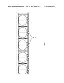
[0033] Still further, the assembly can be supplied in a self-assembly or flat-pack form. An example of this is shown in FIG. 4.
[0034] The accessible voids, whether of an inflated type or preformed concrete form, involve the use of voids that will normally be cast in the concrete by use of in-situ concrete supply.
[0035] The pouring of concrete is made after the on-site grid link up has been completed. This is an important difference that can be drawn between prior art products that have non lined voids, preformed off site, such voids can comprise concrete hollow core units.
[0036] Other benefits that arise through use of the invention are for example:
[0037] 1. It is possible to have a flat soffit
[0038] 2. Reduction in the amount of material necessary to form the floor.
[0039] 3. Reduction of the gravity loads on the frame and sub-structure of the floor.
[0040] 4. Enhanced seismic performance of the floor.
[0041] 5. Allows off-site construction with reduced waste and improved accuracy to permit greater installation speed.
[0042] 6. Reduction in the required labour, overall site programme and costs.
[0043] 7. Permits multiple mechanical and electrical servicing options including active thermal mass integration.
[0044] 8. Significantly improved transportability, with in excess of 1000 m2 of flooring transported by a single truck.
User Contributions:
Comment about this patent or add new information about this topic:
Images included with this patent application:
 |  |
 |  |
 |
| Similar patent applications: | |
| Date | Title |
|---|---|
| 2015-03-26 | H-beam and method for constructing concrete form using h-beam and non-metallic sheathing board |
| New patent applications in this class: | |
| Date | Title |
|---|---|
| 2019-05-16 | Column fixing device for frost prevention machine |
| 2016-06-23 | Reconfigurable support base for a container |
| 2016-06-16 | Wing diamond foundation |
| 2016-06-02 | Polyurethane foam in foundation footings for load-bearing structures |
| 2015-12-31 | Modular monopole tower foundation |
| Top Inventors for class "Static structures (e.g., buildings)" | |
| Rank | Inventor's name |
|---|---|
| 1 | Darko Pervan |
| 2 | Gregory F. Jacobs |
| 3 | Husnu M. Kalkanoglu |
| 4 | Ronald P. Hohmann, Jr. |
| 5 | Mark Cappelle |