Patent application title: METHOD AND DEVICE FOR ALLOCATING RESOURCES TO CARRIER RESPONSE INFORMATION
Inventors:
Peiyan Fei (Shenzhen City, CN)
Focai Peng (Shenzhen City, CN)
IPC8 Class: AH04L500FI
USPC Class:
370311
Class name: Multiplex communications communication over free space signaling for performing battery saving
Publication date: 2014-11-27
Patent application number: 20140348048
Abstract:
A method and apparatus for allocating resources to carrier response
information feedback are disclosed. Wherein, when Transmit Power Control
(TPC) command in Downlink Control Information (DCI) for each secondary
component carrier in carrier aggregation is different, Physical Uplink
Control Channel (PUCCH) resources allocated to the response information
feedback of the secondary component carriers are high-layer configuration
PUCCH resources designated by TPC command in the DCI which triggers data
services in the secondary component carriers. The present solution can
not only effectively feedback response information, but also can
effectively suppress occurrence of unnecessary downlink retransmission.Claims:
1. A method for allocating resources to multi-carrier response
information feedback, wherein, when Transmit Power Control (TPC) command
in Downlink Control Information (DCI) of various secondary component
carriers in carrier aggregation is different, Physical Uplink Control
Channel (PUCCH) resources allocated to response information feedback of
the secondary component carriers are higher layer configuration PUCCH
resources designated by TPC command in the DCI which triggers data
services in the secondary component carriers; when the TPC command in the
DCI of various secondary component carriers is the same, a PUCCH resource
corresponding to a first secondary component carrier, referred to as
nPUCCH,1.sup.(1), is a higher layer configuration PUCCH resource
designated by a TPC command in the DCI which triggers a data service in
the first secondary component carrier; when the number of secondary
component carriers is 2, a PUCCH resource corresponding to a second
secondary component carrier is nPUCCH,2.sup.(1)=.left
brkt-top.nPUCCH,1.sup.(1)+1*c.right brkt-bot.; when the number of
secondary component carriers is 3, a PUCCH resource corresponding to a
third secondary component carrier is nPUCCH,3.sup.(1)=.left
brkt-top.nPUCCH,1.sup.(1)2*c.right brkt-bot.; and when the number of
secondary component carriers is 4, a PUCCH resource corresponding to a
fourth secondary component carrier is nPUCCH,4.sup.(1)=.left
brkt-top.nPUCCH,1.sup.(1)+3c.right brkt-bot., wherein, c is a
resource location adjustment factor, which is a positive integer, and
.left brkt-top. .right brkt-bot. represents rounding up to an integer.
2. The method according to claim 1, wherein, when a Physical Downlink Shared Channel (PDSCH) transmission with a corresponding Physical Downlink Control Channel (PDCCH) or a PDCCH indicating a downlink SPS release on a primary cell is transmitted in a subframe in the carrier aggregation, a PUCCH resource location nPUCCH,0.sup.(1) allocated to response information feedback of the primary cell is a sum of n.sub.CCE,0 and nPUCCH.sup.(1), wherein, n.sub.CCE,0 is the number of the first Control Channel Element (CCE) used for transmission of the PDCCH related to downlink services of the primary cell, and nPUCCH.sup.(1) is a location offset value of a PUCCH resource configured by higher layers; and when the PDSCH transmission with the corresponding PDCCH or the PDCCH indicating the downlink SPS release on the primary cell is not transmitted in the subframe in the carrier aggregation, the PUCCH resource location allocated to the response information feedback of the primary cell is a higher layer configuration PUCCH resource designated by a TPC command in the DCI when downlink Semi Persistent Scheduling (SPS) is triggered.
3. The method according to claim 1, wherein, when a value of the TPC command is 00, the TPC command corresponds to a first PUCCH resource configured by higher layers; when the value of the TPC command is 01, the TPC command corresponds to a second PUCCH resource configured by the higher layers; when the value of the TPC command is 10, the TPC command corresponds to a third PUCCH resource configured by the higher layers; and when the value of the TPC command is 11, the TPC command corresponds to a fourth PUCCH resource configured by the higher layers.
4. The method according to claim 1, wherein, the response information comprises an Acknowledgement (ACK), a Negative Acknowledgement (NACK) and a Discontinuous Transmission (DTX) of a base station.
5. A multi-carrier response information feedback method in carrier aggregation, wherein, a base station allocates Physical Uplink Control Channel (PUCCH) resources to response information feedback of various secondary component carriers in carrier aggregation, and a UE feeds back response information in various secondary component carriers according to the PUCCH resources allocated to various secondary component carriers by the base station; when the Transmit Power Control (TPC) command in Downlink Control Information (DCI) of various secondary component carriers in carrier aggregation is different, PUCCH resources allocated to response information feedback of the secondary component carriers are higher layer configuration PUCCH resources designated by TPC command in the DCI information which triggers data services in the secondary component carriers; when the TPC command in the DCI of various secondary component carriers is the same, a PUCCH resource corresponding to a first secondary component carrier, referred to as nPUCCH,1.sup.(1), is a higher layer configuration PUCCH resource designated by a TPC command in the DCI which triggers a data service in the first secondary component carrier; when the number of secondary component carriers is 2, a PUCCH resource corresponding to a second secondary component carrier is nPUCCH,2.sup.(1)=.left brkt-top.nPUCCH,1.sup.(1)+1*c.right brkt-bot.; when the number of secondary component carriers is 3, a PUCCH resource corresponding to a third secondary component carrier is nPUCCH,3.sup.(1)=.left brkt-top.nPUCCH,1.sup.(1)2*c.right brkt-bot.; and when the number of secondary component carriers is 4, a PUCCH resource corresponding to a fourth secondary component carrier is nPUCCH,4.sup.(1)=.left brkt-top.nPUCCH,1.sup.(1)+3*c.left brkt-top., wherein, c is a resource location adjustment factor, which is a positive integer, and .left brkt-top. .right brkt-bot. represents rounding up to an integer.
6. The method according to claim 5, wherein, the response information includes an Acknowledgement (ACK), a Negative Acknowledgement (NACK) and a Discontinuous Transmission (DTX) of a base station.
7. An apparatus for allocating resources to multi-carrier response information feedback, wherein, the apparatus comprises a Physical Uplink Control Channel (PUCCH) resource configuration module; the PUCCH resource configuration module is configured to allocate PUCCH resources to response information feedback of various secondary component carriers in carrier aggregation, wherein when a Transmit Power Control (TPC) command in a Downlink Control Information (DCI) of various secondary component carriers in carrier aggregation is different, the PUCCH resources allocated to the response information feedback of the secondary component carriers are higher layer configuration PUCCH resources designated by TPC command in the DCI information which triggers data services in the secondary component carriers; the PUCCH resource configuration module is further configured to allocate a PUCCH resource, referred to as nPUCCH,1.sup.(1), to a first secondary component carrier, wherein the nPUCCH,1.sup.(1) is a higher layer configuration PUCCH resource designated by a TPC command in the DCI information which triggers a data service in the first secondary component carrier, when the TPC command in the DCI information of various secondary component carriers is the same; when the number of secondary component carriers is 2, a PUCCH resource allocated to a second secondary component carrier is nPUCCH,2.sup.(1)=.left brkt-top.nPUCCH,1.sup.(1)+1*c.right brkt-bot.; when the number of secondary component carriers is 3, a PUCCH resource allocated to a third secondary component carrier is nPUCCH,3.sup.(1)=.left brkt-top.nPUCCH,1.sup.(1)+2*c.right brkt-bot.; and when the number of secondary component carriers is 4, a PUCCH resource allocated to a fourth secondary component carrier is nPUCCH,4.sup.(1)=.left brkt-top.nPUCCH,1.sup.(1)+3*c.right brkt-bot., wherein, c is a resource location adjustment factor, which is a positive integer greater than 0, and .left brkt-top. .right brkt-bot. represents rounding up to an integer.
8. The apparatus according to claim 7, wherein, the PUCCH resource configuration module is further configured to configure a PUCCH resource location nPUCCH,0.sup.(1) allocated to response information feedback of a primary cell to be a sum of n.sub.CCE,0 and NPUCCH.sup.(1) when a Physical Downlink Shared Channel (PDSCH) transmission with a corresponding Physical Downlink Control Channel (PDCCH) or a PDCCH indicating a downlink SPS services release on the primary cell is transmitted in a subframe in the carrier aggregation, wherein, n.sub.CCE,0 is the number of the first Control Channel Element (CCE) used for transmission of the PDCCH related to downlink services of the primary cell, and nPUCCH.sup.(1) is a location offset value of a PUCCH resource configured by higher layers; and the PUCCH resource configuration module is further configured to configure the PUCCH resource location allocated to the response information feedback of the primary cell to be a higher layer configuration PUCCH resource designated by a TPC command in the DCI when downlink Semi Persistent Scheduling (SPS) is triggered, when the PDSCH transmission with the corresponding PDCCH or the PDCCH indicating the downlink SPS release on the primary cell is not transmitted in the subframe in the carrier aggregation.
9. The apparatus according to claim 7, wherein, when a value of the TPC command is 00, the TPC command corresponds to a first PUCCH resource configured by higher layers; when the value of the TPC command is 01, the TPC command corresponds to a second PUCCH resource configured by the higher layers; when the value of the TPC command is 10, the TPC command corresponds to a third PUCCH resource configured by the higher layers; and when the value of the TPC command is 11, the TPC command corresponds to a fourth PUCCH resource configured by the higher layers.
10. The apparatus according to claim 7, wherein, the response information includes an Acknowledgement (ACK), a Negative Acknowledgement (NACK) and a Discontinuous Transmission (DTX) of a base station.
11. The method according to claim 2, wherein, when a value of the TPC command is 00, the TPC command corresponds to a first PUCCH resource configured by higher layers; when the value of the TPC command is 01, the TPC command corresponds to a second PUCCH resource configured by the higher layers; when the value of the TPC command is 10, the TPC command corresponds to a third PUCCH resource configured by the higher layers; and when the value of the TPC command is 11, the TPC command corresponds to a fourth PUCCH resource configured by the higher layers.
12. The method according to claim 2, wherein, the response information comprises an Acknowledgement (ACK), a Negative Acknowledgement (NACK) and a Discontinuous Transmission (DTX) of a base station.
13. The method according to claim 3, wherein, the response information comprises an Acknowledgement (ACK), a Negative Acknowledgement (NACK) and a Discontinuous Transmission (DTX) of a base station.
14. The apparatus according to claim 8, wherein, when a value of the TPC command is 00, the TPC command corresponds to a first PUCCH resource configured by higher layers; when the value of the TPC command is 01, the TPC command corresponds to a second PUCCH resource configured by the higher layers; when the value of the TPC command is 10, the TPC command corresponds to a third PUCCH resource configured by the higher layers; and when the value of the TPC command is 11, the TPC command corresponds to a fourth PUCCH resource configured by the higher layers.
15. The apparatus according to claim 8, wherein, the response information includes an Acknowledgement (ACK), a Negative Acknowledgement (NACK) and a Discontinuous Transmission (DTX) of a base station.
16. The apparatus according to claim 9, wherein, the response information includes an Acknowledgement (ACK), a Negative Acknowledgement (NACK) and a Discontinuous Transmission (DTX) of a base station.
Description:
TECHNICAL FIELD
[0001] The present invention relates to the field of mobile communications, and in particular, to a method and apparatus for allocating resources to carrier response information feedback.
BACKGROUND OF THE RELATED ART
[0002] With the rapid development of the Long Term Evolution (LTE) system, the 3rd Generation Partnership Project (3GPP) gradually develops research works on Long Term Evolution-Advanced (LTE-Advanced; LTE-A) related technologies. Compared with the LTE system, the LTE-Advanced system has a very large enhancement in terms of key technologies, and has successively introduced the Carrier Aggregation (CA), Relay, Coordinated Multiple Points (COMP), enhanced multi-antenna, uplink multi-antenna, etc.
[0003] In terms of system bandwidth, the LTE-A needs to support higher uplink and downlink transmission rates, the downlink needs to support a data transmission rate of 1 Gbps, and requirements are meet only when the bandwidth reaches to 100 MHz. In addition, the LTE-Advanced needs to be compatible with the LTE. Therefore, carrier aggregation is proposed in the LTE-Advanced. The carrier aggregation may be aggregation in continuous carriers, or may also be aggregation in non-continuous carriers.
[0004] Under the carrier aggregation, the number of component carriers designed by the LTE-A is 5 at most. Thus, for one UE, there may be a large number of bits of the response information fed back in the uplink control channel (including Acknowledgement (ACK), Negative Acknowledgement (NACK), and Discontinuous Transmission (DTX) of the base station). Then in a condition that the power of a User Equipment (UE) is limited, the UE may not transmit enough ACK/NACK information. The current LTE-Advanced system provides an ACK feedback mode of ACK/NACK for a single carrier and dual carriers, but as to an ACK/NACK feedback mode for more than two carriers, there is no solution in the related art.
SUMMARY OF THE INVENTION
[0005] The technical problem to be solved by the present invention is to provide a method and apparatus for allocating resources to carrier response information feedback, which solves a problem of effectively feeding back response information and suppressing unnecessary downlink retransmission in a condition that the number of carriers is greater than 2.
[0006] In order to solve the above technical problem, the present invention provides a method for allocating resources to multi-carrier response information feedback, wherein,
[0007] when Transmit Power Control (TPC) command in Downlink Control Information (DCI) of various secondary component carriers in carrier aggregation is different, Physical Uplink Control Channel (PUCCH) resources allocated to the response information feedback of the secondary component carriers are higher layers configuration PUCCH resources designated by TPC command in the DCI which triggers data services in the secondary component carriers;
[0008] when the TPC command information in the DCI of various secondary component carriers is the same, a PUCCH resource corresponding to a first secondary component carrier, referred to as nPUCCH,1.sup.(1) is a higher-layers configuration PUCCH resource designated by a TPC command in the DCI which triggers a data service in the first secondary component carrier;
[0009] when the number of secondary component carriers is 2, a PUCCH resource corresponding to a second secondary component carrier is nPUCCH,2.sup.(1).left brkt-top.nPUCCH,1.sup.(1)+1*c.right brkt-bot.;
[0010] when the number of secondary component carriers is 3, a PUCCH resource corresponding to a third secondary component carrier is nPUCCH,3.sup.(1)=.left brkt-top.nPUCCH,1.sup.(1)+2*c.right brkt-bot.; and
[0011] when the number of secondary component carriers is 4, a PUCCH resource corresponding to a fourth secondary component carrier is nPUCCH,4=.left brkt-top.nPUCCH,1.sup.(1)+3*c.right brkt-bot.;
[0012] wherein, c is a resource location adjustment factor, which is a positive integer, and .left brkt-top. .right brkt-bot. represents rounding up to an integer.
[0013] Preferably, the above method may further have the following features:
[0014] when a Physical Downlink Shared Channel (PDSCH) transmission with a corresponding Physical Downlink Control Channel (PDCCH) or a PDCCH indicating a downlink SPS release on a primary cell is transmitted in a subframe in the carrier aggregation, a PUCCH resource location nPUCCH,0.sup.(1) allocated to response information feedback of the primary cell is a sum of n.sub.CCE,0 and NPUCCH.sup.(1), wherein, n.sub.CCE,0 is the number of the first Control Channel Element (CCE) used for transmission of the PDCCH related to downlink services of the primary cell, and NPUCCH.sup.(1) is a location offset value of a PUCCH resource configured by higher layers; and
[0015] when the PDSCH transmission with the corresponding PDCCH or the PDCCH indicating the downlink SPS release on the primary cell is not transmitted in the subframe in the carrier aggregation, a PUCCH resource location allocated to response information feedback of the primary cell is higher-layers configuration PUCCH resource designated by a TPC command in the DCI when triggering downlink Semi-Persistent Scheduling (SPS).
[0016] Preferably, the above method may further have the following features:
[0017] when a value of the TPC command is 00, it corresponds to a first PUCCH resource configured by the high layer;
[0018] when the value of the TPC command is 01, it corresponds to a second PUCCH resource configured by the higher layers;
[0019] when the value of the TPC command is 10, it corresponds to a third PUCCH resource configured by the higher layers; and
[0020] when the value of the TPC command is 11, it corresponds to a fourth PUCCH resource configured by the higher layers.
[0021] Preferably, the above method may further have the following features:
[0022] the response message includes an Acknowledgement (ACK), a Negative Acknowledgement (NACK) and a Discontinuous Transmission (DTX) of a base station.
[0023] In order to solve the above technical problem, the present invention further provides a multi-carrier response information feedback method in carrier aggregation, wherein,
[0024] a base station allocates Physical Uplink Control Channel (PUCCH) resources to response information feedback of various secondary component carriers in carrier aggregation, and a UE feeds back response information in various secondary component carriers according to the PUCCH resources allocated to various secondary component carriers by the base station;
[0025] when Transmit Power Control (TPC) command information in Downlink Control Information (DCI) of various secondary component carriers in carrier aggregation is different, PUCCH resources allocated to the response information feedback of the secondary component carriers are higher-layer configuration PUCCH resources designated by TPC command in the DCI which triggers data services in the secondary component carriers;
[0026] when the TPC command in the DCI of various secondary component carriers is the same, a PUCCH resource corresponding to a first secondary component carrier, referred to as nPUCCH,1.sup.(1) is a higher layer configuration PUCCH resource designated by a TPC command in the DCI which triggers a data service in the first secondary component carrier;
[0027] when the number of secondary component carriers is 2, a PUCCH resource corresponding to a second secondary component carrier is nPUCCH,2.sup.(1)=.left brkt-top.nPUCCH,1.sup.(1)+1*c.right brkt-bot.;
[0028] when the number of secondary component carriers is 3, a PUCCH resource corresponding to a third secondary component carrier is nPUCCH,3.sup.(1)=.left brkt-top.nPUCCH,1.sup.(1)+2*c.right brkt-bot.; and
[0029] when the number of secondary component carriers is 4, a PUCCH resource corresponding to a fourth secondary component carrier is nPUCCH,4.sup.(1)=.left brkt-top.nPUCCH,1.sup.(1)+3*c.right brkt-bot.,
[0030] wherein, c is a resource location adjustment factor, which is a positive integer greater than 0, and .left brkt-top. .right brkt-bot. represents rounding up to an integer.
[0031] Preferably, the above method may further have the following features:
[0032] the response message includes an Acknowledgement (ACK), a Negative Acknowledgement (NACK) and a Discontinuous Transmission (DTX) of a base station.
[0033] In order to solve the above technical problem, the present invention further provides an apparatus for allocating resources to multi-carrier response information feedback, wherein, the apparatus comprises a Physical Uplink Control Channel (PUCCH) resource configuration module;
[0034] the PUCCH resource configuration module is configured to allocate PUCCH resources to response information feedback of various secondary component carriers in carrier aggregation, wherein when Transmit Power Control (TPC) command in Downlink Control Information (DCI) of various secondary component carriers in carrier aggregation is different, the PUCCH resources allocated to the response information feedback of the secondary component carriers are higher-layer configuration PUCCH resources designated by TPC command in the DCI which triggers data services in the secondary component carriers;
[0035] the PUCCH resource configuration module is further configured to allocate a PUCCH resource, referred to as nPUCCH,1.sup.(1), to a first secondary component carrier, wherein nPUCCH,1.sup.(1) is a higher-layer configuration PUCCH resource designated by a TPC command in the DCI which triggers a data service in the first secondary component carrier, when the TPC command in the DCI of various secondary component carriers is the same;
[0036] when the number of secondary component carriers is 2, a PUCCH resource allocated to a second secondary component carrier is nPUCCH,2.sup.(1)=.left brkt-top.nPUCCH,1.sup.(1)+1*c.right brkt-bot.;
[0037] when the number of secondary component carriers is 3, a PUCCH resource allocated to a third secondary component carrier is nPUCCH,3.sup.(1)=.left brkt-top.nPUCCH,1.sup.(1)+2*c.right brkt-bot.; and
[0038] when the number of secondary component carriers is 4, a PUCCH resource allocated to a fourth secondary component carrier is nPUCCH,4.sup.(1)=.left brkt-top.nPUCCH,1.sup.(1)*3c.right brkt-bot.,
[0039] wherein, c is a resource location adjustment factor, which is a positive integer greater than 0, and .left brkt-top. .right brkt-bot. represents rounding up to an integer.
[0040] Preferably, the above apparatus may further have the following features:
[0041] the PUCCH resource configuration module is further configured to configure a PUCCH resource location nPUCCH,0.sup.(1) allocated to response information feedback of a primary cell to be a sum of n.sub.CCE,0 and NPUCCH.sup.(1) when a Physical Downlink Shared Channel (PDSCH) with a corresponding Physical Downlink Control Channel (PDCCH) or a PDCCH indicating a downlink SPS services release on the primary cell is transmitted in a subframe in the carrier aggregation, wherein, n.sub.CCE,0 is the number of the first Control Channel Element (CCE) used for transmission of the PDCCH related to downlink services of the primary cell, and NPUCCH.sup.(1) is a location offset value of a PUCCH resource configured by the higher layer; and
[0042] the PUCCH resource configuration module is further configured to configure a PUCCH resource location allocated to response information feedback of the primary cell to be a higher-layer configuration PUCCH resource designated by a TPC command in the DCI when downlink Semi Persistent Scheduling (SPS) is triggered, when the PDSCH with the corresponding PDCCH or the PDCCH indicating the downlink SPS release on the primary cell is not transmitted in the subframe in the carrier aggregation.
[0043] Preferably, the above apparatus may further have the following features:
[0044] when the value of the TPC command is 00, it corresponds to a first PUCCH resource configured by higher layers;
[0045] when the value of the TPC command is 01, it corresponds to a second PUCCH resource configured by the high layer;
[0046] when the value of the TPC command is 10, it corresponds to a third PUCCH resource configured by the higher layers; and
[0047] when the value of the TPC command is 11, it corresponds to a fourth PUCCH resource configured by the higher layers.
[0048] Preferably, the above apparatus may further have the following features:
[0049] the response message includes an Acknowledgement (ACK), a Negative Acknowledgement (HACK) and a Discontinuous Transmission (DTX) of the base station.
[0050] The embodiments of the present invention provide a response message feedback method and system when the number of carriers is greater than 2, which can not only effectively feedback response information, but also can effectively suppress occurrence of unnecessary downlink data retransmission.
BRIEF DESCRIPTION OF DRAWINGS
[0051] FIG. 1 is a diagram of an apparatus for allocating resources to multi-carrier response information feedback.
PREFERRED EMBODIMENTS OF THE PRESENT INVENTION
[0052] PUCCH resources allocated to response message feedback of various carriers when the number of carriers in carrier aggregation is 3, 4 or 5 are shown in table 1, wherein, PCC represents a primary component carrier, SCC represents a secondary component carrier, SCC1 represents a first secondary component carrier, SCC2 represents a second secondary component carrier, SCC3 represents a third secondary component carrier, and SCC4 represents a fourth secondary component carrier.
TABLE-US-00001 TABLE 1 Number PCC SCC1 SCC2 SCC3 SCC4 of carriers i = 0 i = 1 i = 2 i = 3 i = 4 3 Resource 1 Resource 2 Resource 3 NA NA 4 Resource 1 Resource 2 Resource 3 Resource 4 NA 5 Resource 1 Resource 2 Resource 3 Resource 4 Resource 4
[0053] A method for allocating resources to multi-carrier response information feedback comprises the following contents.
[0054] When Transmit Power Control (TPC) command in Downlink Control Information (DCI) of various secondary component carriers in carrier aggregation is different, Physical Uplink Control Channel (PUCCH) resources allocated to the response information feedback of the secondary component carriers are higher layers configuration PUCCH resources designated by TPC command in the DCI information which triggers data services in the secondary component carriers.
[0055] The TPC command is different from a TPC command in the DCI which triggers a downlink SPS in the PCC.
[0056] For example, as shown in table 2, nPUCCH.sup.(1) represents a PUCCH resource allocated to a ith SCC.
TABLE-US-00002 TABLE 2 TPC value in a DCI field which triggers a downlink data service in the ith SCC The value of TPC command nPUCCH,i.sup.(1) `00` The first PUCCH resource configured by the higher layers `01` The second PUCCH resource configured by the higher layers `10` The third PUCCH resource configured by the higher layers `11` The fourth PUCCH resource configured by the higher layers
[0057] Wherein, the value of the TPC command and the location of the PUCCH resources configured by the higher layers are not limited to the correspondence in the above table, and may also be in another correspondence.
[0058] When the TPC command in the DCI of various secondary component carriers is the same, a PUCCH resource corresponding to a first secondary component carrier, referred to as nPUCCH.sup.(1), is a higher layer configuration PUCCH resource designated by a TPC command in the DCI which triggers a data service in the secondary component carrier, as indicated in the allocation mode in table 2.
[0059] When the number of secondary component carriers is 2, a PUCCH resource corresponding to a second secondary component carrier SCC2 is nPUCCH,2.sup.(1)=.left brkt-top.nPUCCH,1.sup.(1)1*c.right brkt-bot.;
[0060] when the number of secondary component carriers is 3, a PUCCH resource corresponding to a third secondary component carrier SCC3 is nPUCCH,3.sup.(1)=.left brkt-top.nPUCCH,1.sup.(1)2*c.right brkt-bot.; and
[0061] when the number of secondary component carriers is 4, a PUCCH resource corresponding to a fourth secondary component carrier SCC4 is nPUCCH,4.sup.(1)=.left brkt-top.nPUCCH,1.sup.(1)3*c.right brkt-bot.;
[0062] wherein, c is a resource location adjustment factor, which is a positive integer greater than 0, and .left brkt-top. .right brkt-bot. represents rounding up to an integer.
[0063] In the above method, PUCCH resources corresponding to various carriers are different.
[0064] A method for allocating PUCCH resources to response message feedback of a primary component carrier in carrier aggregation comprises the following contents. Firstly, when a Physical Downlink Shared Channel (PDSCH) with a corresponding Physical
[0065] Downlink Control Channel (PDCCH) or a PDCCH indicating a downlink SPS release on the primary cell is transmitted in a subframe in the carrier aggregation, a PUCCH resource location nPUCCH,0.sup.(1) allocated to response information feedback of the primary cell is a sum of n.sub.CCE,0 and nPUCCH.sup.(1), wherein, n.sub.CCE,0 is the number of the first Control Channel Element (CCE) used for transmission of the PDCCH related to downlink services of the primary cell, and NPUCCH.sup.(1) is a location offset value of a PUCCH resource configured by the higher layer.
[0066] Secondly, when the PDSCH with the corresponding PDCCH or the PDCCH indicating the downlink SPS release on the primary cell is not transmitted in the subframe in the carrier aggregation, a PUCCH resource location allocated to response information feedback of the primary cell is a higher layer configuration PUCCH resource designated by a TPC command in the DCI when the downlink Semi-Persistent Scheduling (SPS) is triggered.
[0067] For example, as shown in table 3, a value of TPC is one of four values in table 2, wherein, nPUCCH,0.sup.(1) represents a PUCCH resource allocated to a primary component carrier.
TABLE-US-00003 TABLE 3 TPC value in a DCI field which triggers a downlink SPS The value of TPC command nPUCCH,0.sup.(1) `00` The first PUCCH resource configured by the higher layers `01` The second PUCCH resource configured by the higher layers `10` The third PUCCH resource configured by the higher layers `11` The fourth PUCCH resource configured by the higher layers
[0068] Wherein, the value of the TPC command and the location of the PUCCH resources configured by the higher layer are not limited to the correspondence in the above table, and may also be in another correspondence.
[0069] The response message includes an Acknowledgement (ACK), a Negative Acknowledgement (NACK) and a Discontinuous Transmission (DTX) of a base station.
[0070] An apparatus for allocating resources to multi-carrier response information feedback corresponding to the above method is located at a base station side. As shown in FIG. 1, the apparatus comprises a Physical Uplink Control Channel (PUCCH) resource configuration module; and the mode of the module allocating PUCCH resources to the response message feedback of various carriers in carrier aggregation is the same as what is described in the above method, and the description thereof will be omitted.
[0071] On basis of the above method, after the base station uses the above method to allocate PUCCH resources to response information feedback of various secondary component carriers, the UE feeds back response information in various secondary component carriers according to the PUCCH resources allocated to various secondary component carriers by the base station. Specifically, after the UE obtains the PUCCH resources, the UE corresponds the ACK/NACK information in the current carrier of the UE to a PUCCH resource, and then corresponds the PUCCH resource to the 2-bit information of b(0)b(1), thus implementing transmitting corresponding ACK/NACK information to the base station by the UE using a PUCCH1b format.
[0072] With the ACK/NACK feedback method described above, it can effectively solve a problem of a UE feeding back an ACK/NACK to a base station in a condition that the number of carriers is greater than 2, which can effectively suppress unnecessary data retransmission initiated by the base station due to failure of ACK/NACK feedback, thus effectively enhancing the throughput of the LTE-Advanced system.
[0073] The present solution will be described below using specific embodiments.
Specific Embodiment One
[0074] The number of carriers configured by the UE is 3. There is one primary component carrier, a PDSCH transmission on the primary cell is with a corresponding PDCCH, there are two secondary component carriers, and c=1. Then, PUCCH resources corresponding to the secondary component carriers are as follows.
[0075] SCC1: nPUCCH,1.sup.(1)=nPUCCH,i.sup.(1), which is given by higher layers, and it is sent to the UE through a
[0076] TPC command in the DCI, and the value of the TPC is shown in table 2.
[0077] SCC2: nPUCCH,2.sup.(1)=nPUCCH,1.sup.(1)1.
[0078] A PDSCH transmission on the primary cell is with a corresponding PDCCH, and a resource corresponding to the primary component carrier is:
nPUCCH,0.sup.(1)=n.sub.CCE,0+NPUCCH.sup.(1)
[0079] n.sub.CCE,0 is the number of the first CCE used for transmission of the PDCCH related to downlink services of the PCC.
[0080] A mapping relationship between 2 bits of the PUCCH1b constructed at the UE side and the PUCCH resources and ACK/NACK corresponding to downlink data of various carriers is as follows.
TABLE-US-00004 TABLE 4 Mapping table between ACK/NACK information and PUCCH1b resources when the number of carriers is 3 PCC SCC1 SCC2 nPUCCH,i.sup.(1) b(0)b(1) ACK ACK ACK nPUCCH,1.sup.(1) 1,1 ACK ACK NACK/DTX nPUCCH,1.sup.(1) 1,0 ACK NACK/DTX ACK nPUCCH,1.sup.(1) 0,1 NACK/DTX ACK ACK nPUCCH,2.sup.(1) 1,1 ACK NACK/DTX NAXK/DTX nPUCCH,0.sup.(1) 1,1 NACK/DTX ACK NACK/DTX nPUCCH,0.sup.(1) 1,0 NACK/DTX NACK/DTX ACK nPUCCH,0.sup.(1) 0,1 NACK NACK NACK nPUCCH,2.sup.(1) 0,0 NACK DTX DTX nPUCCH,0.sup.(1) 0,0 DTX NACK DTX nPUCCH,0.sup.(1) 0,0 DTX DTX NACK nPUCCH,2.sup.(1) 0,0 DTX DTX DTX no transmission of PUCCH
[0081] This table is an example of the present embodiment, and a correspondence between the PUCCH resources and the ACK/NACK feedback is not limited thereto.
Specific Embodiment Two
[0082] The number of carriers configured by the UE is 4. There is one primary component carrier, a PDSCH transmission on the primary cell is without a corresponding PDCCH, there are three secondary component carriers, and c=1. Then, PUCCH resources corresponding to the secondary component carriers are as follows.
[0083] SCC1: nPUCCH,1.sup.(1)=nPUCCH,j.sup.(1), which is given by higher layers, and it is sent to the UE through a TPC command in the DCI, and the value of the TPC is shown in table 2.
[0084] SCC2: nPUCCH,2.sup.(1)=nPUCCH,1.sup.(1)1.
[0085] SCC3: nPUCCH,3.sup.(1)=nPUCCH,1.sup.(1)2.
[0086] a PDSCH transmission on the primary cell is without a corresponding PDCCH, thus the resource corresponding to the primary component carrier is consistent with the PUCCH resource information represented by the TPC command in the related DCI information in the PCC. Assume that TPC=00, then nPUCCH,0.sup.(1) is the first PUCCH resource configured by higher layers which is represented by "00", and the specific values are shown in table 3.
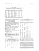
[0087] A mapping relationship between 2 bits of the PUCCH1b constructed at the UE side and the PUCCH resources and ACK/NACK corresponding to downlink data of various carriers are as follows.
TABLE-US-00005 TABLE 5 Mapping table between ACK/NACK information and PUCCH1b resources when the number of carriers is 4 PCC SCC1 SCC2 SCC3 nPUCCH,i.sup.(1) b(0)b(1) ACK ACK ACK ACK nPUCCH,1.sup.(1) 1,1 ACK ACK ACK NACK/DTX nPUCCH,2.sup.(1) 0,1 ACK ACK NACK/DTX ACK nPUCCH,1.sup.(1) 0,1 ACK NACK/DTX ACK ACK nPUCCH,3.sup.(1) 1,1 NACK/DTX ACK ACK ACK nPUCCH,1.sup.(1) 1,0 NACK/DTX NACK/DTX ACK ACK nPUCCH,2.sup.(1) 0,0 ACK NACK/DTX NACK/DTX ACK nPUCCH,1.sup.(1) 0,0 ACK ACK NACK/DTX NACK/DTX nPUCCH,3.sup.(1) 1,0 NACK/DTX ACK ACK NACK/DTX nPUCCH,2.sup.(1) 1,1 NACK/DTX NACK/DTX NACK/DTX ACK nPUCCH,2.sup.(1) 1,0 ACK NACK/DTX NACK/DTX NACK/DTX nPUCCH,3.sup.(1) 0,1 NACK/DTX ACK NACK/DTX NACK/DTX nPUCCH,3.sup.(1) 0,0 NACK/DTX NACK/DTX ACK NACK/DTX nPUCCH,0.sup.(1) 1,1 NACK NACK/DTX NACK/DTX NACK/DTX nPUCCH,0.sup.(1) 1,0 NACK/DTX NACK NACK/DTX NACK/DTX nPUCCH,0.sup.(1) 0,1 NACK/DTX NACK/DTX NACK NACK/DTX nPUCCH,0.sup.(1) 0,0 NACK/DTX NACK/DTX NACK/DTX NACK nPUCCH,0.sup.(1) 0,0 DTX DTX DTX DTX no transmission of PUCCH
[0088] This table is an example of the present embodiment, and a correspondence between the PUCCH resources and the ACK/NACK feedback is not limited thereto.
Specific Embodiment Three
[0089] The number of carriers configured by the UE is 5. There is one primary component carrier, a PDSCH transmission on the primary cell is with a corresponding PDCCH, there are four secondary component carriers, and c=1. Then, PUCCH resources corresponding to the secondary component carriers are as follows.
[0090] SCC1: nPUCCH,1.sup.(1)=nPUCCH,i.sup.(1), which is given by higher layers, and it is sent to the UE through a TPC command in the DCI, and the value of the TPC is shown in table 2.
[0091] SCC2:nPUCCH,2.sup.(1)=nPUCCH,1.sup.(1)+1.
[0092] SCC3: nPUCCH,3.sup.(1)=nPUCCH,1.sup.(1)2.
[0093] SCC4: nPUCCH,4.sup.(1)=nPUCCH,1.sup.(1)+3.
[0094] a PDSCH transmission on the primary cell is with a corresponding PDCCH, and a resource corresponding to the primary component carrier is:
nPUCCH,0.sup.(1)=n.sub.CCE,0+PUCCH.sup.(1)
n.sub.CCE,0 is the number of the first CCE used for transmission of the PDCCH related to downlink services of the PCC.
[0095] A mapping relationship between 2 bits of the PUCCH 1b constructed at the UE side and the PUCCH resources and ACK/NACK corresponding to downlink data of various carriers is as follows.
TABLE-US-00006 TABLE 6 Mapping table between ACK/NACK information and PUCCH1b resources when the number of carriers is 5 PCC SCC1 SCC2 SCC3 SCC4 nPUCCH, i.sup.(1) b(0)b(1) ACK ACK ACK ACK ACK nPUCCH, 1.sup.(1) 1, 1 ACK ACK ACK ACK NACK/ nPUCCH, 2.sup.(1) 0, 1 DTX ACK ACK ACK NACK/ ACK nPUCCH, 1.sup.(1) 0, 1 DTX ACK ACK NACK/ ACK ACK nPUCCH, 3.sup.(1) 1, 1 DTX ACK NACK/ ACK ACK ACK nPUCCH, 1.sup.(1) 1, 0 DTX NACK/ ACK ACK ACK ACK nPUCCH, 2.sup.(1) 0, 0 DTX ACK ACK ACK NACK/ NACK/ nPUCCH, 1.sup.(1) 0, 0 DTX DTX ACK ACK NACK/ NACK/ ACK nPUCCH, 3.sup.(1) 1, 0 DTX DTX ACK NACK/ NACK/ ACK ACK nPUCCH, 2.sup.(1) 1, 1 DTX DTX NACK/ NACK/ ACK ACK ACK nPUCCH, 2.sup.(1) 1, 0 DTX DTX NACK/ ACK ACK ACK NACK/ nPUCCH, 3.sup.(1) 0, 1 DTX DTX ACK NACK/ NACK/ NACK/ ACK nPUCCH, 3.sup.(1) 0, 0 DTX DTX DTX ACK ACK NACK/ NACK/ NACK/ nPUCCH, 0.sup.(1) 1, 1 DTX DTX DTX NACK/ NACK/ NACK/ ACK ACK nPUCCH, 0.sup.(1) 1, 0 DTX DTX DTX NACK/ NACK/ ACK ACK NACK/ nPUCCH, 0.sup.(1) 0, 1 DTX DTX DTX NACK/ ACK ACK NACK/ NACK/ nPUCCH, 0.sup.(1) 0, 0 DTX DTX DTX NACK/ NACK/ NACK/ NACK/ ACK nPUCCH, 4.sup.(1) 0, 0 DTX DTX DTX DTX NACK/ NACK/ NACK/ ACK NACK/ nPUCCH, 4.sup.(1) 1, 1 DTX DTX DTX DTX NACK/ NACK/ ACK NACK/ NACK/ nPUCCH, 4.sup.(1) 1, 0 DTX DTX DTX DTX NACK/ ACK NACK/ NACK/ NACK/ nPUCCH, 4.sup.(1) 0, 1 DTX DTX DTX DTX ACK NACK/ NACK/ NACK/ NACK/ nPUCCH, 2.sup.(1) 1, 1 DTX DTX DTX DTX NACK/ NACK/ NACK/ NACK/ NACK/ nPUCCH, 2.sup.(1) 1, 0 DTX DTX DTX DTX DTX
[0096] This table is an example of the present embodiment, and a correspondence between the PUCCH resources and the ACK/NACK feedback is not limited thereto.
[0097] It should be illustrated that, in the case of no conflict, the embodiments of this application and the features in the embodiments could be combined randomly with each other.
[0098] Of course, the present invention can have a plurality of other embodiments. Without departing from the spirit and substance of the present invention, those skilled in the art can make various corresponding changes and variations according to the present invention, and all these corresponding changes and variations should belong to the protection scope of the appended claims in the present invention.
[0099] A person having ordinary skill in the art can understand that all or a part of steps in the above method can be implemented by programs instructing related hardware, and the programs can be stored in a computer readable storage medium, such as a read-only memory, a disk or a disc etc. Alternatively, all or a part of steps in the above examples can also be implemented by one or more integrated circuits. Accordingly, each module/unit in the above embodiments can be implemented in the form of hardware, or can also be implemented in the form of software functional module. The present invention is not limited to any particular form of a combination of hardware and software.
INDUSTRIAL APPLICABILITY
[0100] The embodiments of the present invention provide a response message feedback method and system when the number of carriers is greater than 2, which can not only effectively feedback response information, but also can effectively suppress occurrence of unnecessary downlink data retransmission.
User Contributions:
Comment about this patent or add new information about this topic:
Images included with this patent application:
 |  |
 |  |
| Similar patent applications: | |
| Date | Title |
|---|---|
| 2014-10-30 | Method and device for video transmission |
| 2014-11-06 | Method of reporting scheduling information |
| 2014-09-25 | Method and device of supporting group mobility |
| 2014-12-04 | Methods and devices for processing a data frame |
| 2014-11-27 | Control channel design for new carrier type (nct) |
| New patent applications in this class: | |
| Date | Title |
|---|---|
| 2022-05-05 | Facilitation of power retention for 5g or other next generation network non-standalone devices |
| 2022-05-05 | Provision of time information to a wireless device |
| 2022-05-05 | Network device management |
| 2022-05-05 | Method of controlling plurality of cells for providing radio resources to plurality of user equipments, and electronic device for performing the method |
| 2019-05-16 | Method and apparatus for transceiving wireless signal in wireless communication system |
| New patent applications from these inventors: | |
| Date | Title |
|---|---|
| 2017-05-18 | Resource preemption method, station and computer storage medium |
| 2012-08-02 | Method and device for rank adaptation |
| Top Inventors for class "Multiplex communications" | |
| Rank | Inventor's name |
|---|---|
| 1 | Peter Gaal |
| 2 | Wanshi Chen |
| 3 | Tao Luo |
| 4 | Hanbyul Seo |
| 5 | Jae Hoon Chung |